1
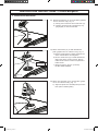
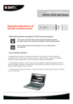
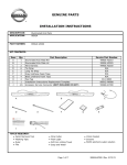
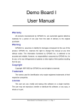
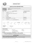
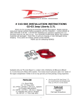
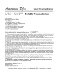
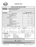
GENUINE PARTS INSTALLATION INSTRUCTIONS 1. DESCRIPTION: 2. APPLICATION: 3. PART NUMBER: 4. KIT CONTENTS (999Q5 GU01X): Item QTY A Nissan Portable Navigation Rogue 2008 Common Mount NAVI kit (999Q5 GU012) Description Service Parts 1 Wire harness assembly Order 999Q5 GU002 (incl. items A-L) B 1 Mounting template (Rogue) C 8 Fasteners (dash attachment plate) 3×25mm, 3×10mm D 1 Dash attachment plate E 1 Nut plate F 3 Fasteners (base to dash attachment plate) 3×9mm G 1 Mount base H 1 Arm assembly I 1 Wire tap J 1 Decorative cover K 1 Installation Instructions (Rogue) L 4 Cable ties 200mm (7.9”) 1 NAVI, USB cable, charger, carry case, and instructions M NISSAN ROGUE TEMPLATE 190-00822-14 999Q5 KU000 for repl nuvi 750 VEHICLE FRONT TAPE TAPE GENUINE PARTS ALIGN HATCHED EDGES TO DASH INSTALLATION INSTRUCTIONS 1. 2. 3. 5/32" (4mm) HOLES 4X 4. DESCRIPTION: Nissan Portable Navigation APPLICATION: Rogue 2008 PART NUMBER: • Portable Navigation Device (PND) main kit (999Q5 KU000) • PND housing (999Q5 GU00) KIT CONTENTS (PND Housing): Item QTY A Description Wire harness assembly B Mounting template (Rogue) C 8 Fastners (dash attachment plate) D E Image is for reference only Nut plate 3 Fastners (base to dash attachment plate) 3×8mm Mount base I Arm assembly J Wire tap K 3×30; 3×0mm Dash attachment plate F G H Decorative cover Installation Instructions (Rogue) NISSAN ROGUE TEMPLATE 190-00822-14 VEHICLE FRONT TAPE TAPE ALIGN HATCHED EDGES TO DASH 5/32" (4mm) HOLES 4X TAPE TAPE 5/32" (4mm) PILOT FOR 3/4" HOLE TAPE 5/32" (4mm) PILOT FOR 3/4" HOLE A 5. 6. B C D TOOLS REQUIRED: • Drill • 5/32” (4mm) drill bit • Phillips screwdrivers (#, #2) • Masking tape (3”) E F G H I J K • Plastic pry bar • 3/4” (9mm) hole saw • Electrical tape • Plastic (PGF) remover tool PRE-INSTALL CAUTIONS/NOTES: Dealer installation reccommended. Instructions refer to Service Manual. k CAUTION • Use caution when removing/re-installing interior components to avoid damage, scratches, or breaking of mounting clips. • The following steps are critical and must be performed EXACTLY as specified to ensure proper installation: • Remove cluster lid C • Install mounting plate and base • Install wire tap TAPE 90-00822-04 REV. A A B 5. C D E F G H I J Page of 3 K 999Q5 QU00 II REV N 2-20-07 L M TOOLS REQUIRED 6. • Right angle drill with positive drill stop • Masking tape (3“ in width) • Electrical tape • 5/32” (4mm) drill bit • Plastic PGF remover tool • Multimeter • Magnetic screwdriver (#1, #2 phillips) • 3/4” (19mm) hole saw PRE-INSTALL CAUTIONS/NOTES: Dealer installation recommended. Instructions refer to Service Manual ‹ CAUTION • The following steps are critical and must be performed EXACTLY as specified: • Remove cluster lid C • Template application and drilling operation • I nstall dash attachment plate (D) and mount base (G) • Install wire tap NOTE • This is a universal installation kit so all parts may not be used. 190-00822-04 REV. C 190-00822-04_0C.indd 1 Page of 13 999Q5 GU100 II REV 2 06-10-08 6/11/2008 8:44:22 AM INSTALLATION INSTRUCTIONS - Portable Navigation 7. INSTALLATION PROCEDURE: 1) Apply the parking brake. 2) Record the customer radio presets. Preset 1 2 3 4 5 6 7 A B C D 3) Make sure the shift lever is engaged in the “P” position and the parking brake is ON. 4) Turn the ignition switch OFF. 5) Open the engine hood. 6) Disconnect the battery negative terminal. ‹ CAUTION •Use caution when removing/re-installing interior components to avoid damage, scratches, or breaking of mounting clips. Apply masking tape Fig. 1 7) R emove cluster lid D. Fig. 1 a)Apply masking tape to sides of cluster lid D. b)Ensure parking brake is set. c)Push shift lock and move shift lever to N or D. d) Use PGF stick and pry cluster lid D at pawl (triangle) locations. Fig. 1 e)Remove cluster lid D. f) Move shift lever back to P. g)Refer to service manual for more details. D Fig. 2 190-00822-04 REV. C 190-00822-04_0C.indd 2 8) R emove center speaker grill (with BOSE audio). Fig. 2 a) U se PGF stick and remove center speaker grille (1) at forward pawl (triangle) locations. Fig. 2 b) Remove 4 screws from center speaker. c) Pull speaker up and disconnect connector. Page of 13 999Q5 GU100 II REV 2 06-10-08 6/11/2008 8:44:23 AM INSTALLATION INSTRUCTIONS - Portable Navigation 7. INSTALLATION PROCEDURE: Fig. 3 C Fig. 4 Fig. 5 Remove (1) fastener 190-00822-04 REV. C 190-00822-04_0C.indd 3 9) R emove cluster lid C. Fig. 3 a) I nsert PGF stick at metal clip point and begin removal at these 2 points. b) Remove cluster lid. 10) R emove audio unit (1). Fig. 4 a) Remove 4 fasteners (A). b) Disconnect connectors. c) For more details refer to service manual. 11) R emove HVAC duct assembly. Fig. 5 a) Remove (1) fastener (two views). b) R emove duct. Pull toward the rear of the vehicle to disengage duct from HVAC ports. Maneuver HVAC duct through the audio opening. Page of 13 999Q5 GU100 II REV 2 06-10-08 6/11/2008 8:44:24 AM INSTALLATION INSTRUCTIONS - Portable Navigation 7. INSTALLATION PROCEDURE: Fig. 6a Cover HVAC ports with masking tape 12)Prepare vehicle for drilling into the dash. a) H VAC ports: protect from debris by covering the openings with masking tape. Fig. 6a b) I nstrument cluster: cover dash and gauges to protect from debris. Fig. 6b Fig. 6b Cover area with cloth Fig. 7 190-00822-04 REV. C 190-00822-04_0C.indd 4 13) Drill mounting holes. Fig. 7 a) I nstall Rogue mounting template (B) to dash using masking tape. b) D rill five-5/32” (4mm) holes (4 + 1 pilot hole in the center). c) D rill one-3/4” (19mm) hole (in the center location). d) Remove mounting template from dash. Page of 13 999Q5 GU100 II REV 2 06-10-08 6/11/2008 8:44:25 AM INSTALLATION INSTRUCTIONS - Portable Navigation 7. INSTALLATION PROCEDURE: C Fig. 8a 14)Secure dash attachment plate to dash (graphics are for reference only). a) Align dash attachment plate (D) with round nutplate (E) under the dash. Fig. 8a D Note: Ensure nuts on nutplate (E) are facing down and the triangle on the dash plate (D) is facing towards the rear of the vehicle. Fig. 8b b) S ecure using four-3×25mm fasteners (C). Torque fasteners to 10 in-lb (1.13 N-m). Fig. 8c Ensure that the bottom plate sits flush with the ribs, and that all four screws are securely tightened. Fig. 8d E 1.13 N-m Fig. 8b Point towards rear of vehicle Fig. 8c 1.13 N-m Fig. 8d 190-00822-04 REV. C 190-00822-04_0C.indd 5 Page of 13 999Q5 GU100 II REV 2 06-10-08 6/11/2008 8:44:26 AM INSTALLATION INSTRUCTIONS - Portable Navigation 7. INSTALLATION PROCEDURE: Fig. 9a 15) Route wire harness and secure ground wire. a) R oute connector up through instrument panel. Fig. 9a b) Route harness (A) behind bracket. Fig. 9b c) S ecure ground wire in the 2 o’clock position. Fig. 9b and Fig. 9c d) S ecure cable to existing main harness and excess ground wire cable with cable ties in two locations. Fig. 9c Fig. 9b Ground location Cable tie to main harness in two locations Fig. 9c Ground location Secure excess ground wire in cable tie 190-00822-04 REV. C 190-00822-04_0C.indd 6 Page of 13 999Q5 GU100 II REV 2 06-10-08 6/11/2008 8:44:26 AM INSTALLATION INSTRUCTIONS - Portable Navigation 7. INSTALLATION PROCEDURE: Fig. 10 G 16) A ttach wire harness (A) to mount base (graphics are for reference only). Fig. 10 a) Firmly press connector into mount base (G). b) C onfirm connector lock is engaged by tugging slightly on the wire harness. A Fig. 11 F 17) A ttach mount base (G) to dash attachment plate (graphics are for reference only). Fig. 11 a) E nsure release button is facing towards rear of the vehicle before securing base. b) S ecure mount base (G) to dash attachment plate using three-3×9mm screws. Ensure rubber skirt is flared out and not pinched or folded under. c) T orque screws to .56 N-m (4.9 in-lb). DO NOT OVER-TORQUE. G Point towards rear of vehicle .56 N-m Fig. 12 18) A ttach arm assembly (H) to mount base (graphics are for reference only). Fig. 12 H 190-00822-04 REV. C 190-00822-04_0C.indd 7 a) A lign and press arm assembly firmly into the base (three retaining tabs). Page of 13 999Q5 GU100 II REV 2 06-10-08 6/11/2008 8:44:27 AM INSTALLATION INSTRUCTIONS - Portable Navigation 7. INSTALLATION PROCEDURE: 19)Secure gray end of the wire tap (I) to (blue wire with silver band - reference only) (pin 7). Connector view releasing tab facing up. Fig. 13 See steps 20-24 for wire tap installation instructions. Fig. 13 PIN 7 BLUE WIRE 7 Pin 6 White wire Pin 8 Yellow wire Harness side of connector Fig. 14 b) a) 20) Tap vehicle wire. Fig. 14 a) Remove cap (slot side) from tap body. b) Slide cap around vehicle wire. c) Tighten the tap TIGHT with finger pressure. NOTE: Do not re-use the tap for subsequent re-installation. c) Fig. 15 21)Inspect the tap to ensure correct installation. Fig. 15 NOTE: Avoid putting pressure on the vehicle wire and tap for the rest of the installation. i. Straight and evenly spaced all the way around. ii.Tight and minimize gap (wire jacket should be crushed). 190-00822-04 REV. C 190-00822-04_0C.indd 8 Page of 13 999Q5 GU100 II REV 2 06-10-08 6/11/2008 8:44:28 AM INSTALLATION INSTRUCTIONS - Portable Navigation 7. INSTALLATION PROCEDURE: Fig. 16 e) Insert wire to here c) a) d) f) Tighten Fig. 17 Fig. 18 b) Existing harness 190-00822-04 REV. C 190-00822-04_0C.indd 9 23)Confirm installation of the tapped accessory wire. Fig. 17 a) I nspect the tap to ensure correct installation. b) Using a multimeter, check for 12 volts on the accessory wire. NOTE: Avoid putting pressure on the vehicle wire and tap for the rest of the installation. i. Straight and evenly spaced all around ii. Tight and no gap iii. Test the signal a) 22)Tap red wire from housing harness. Fig. 16 a) Remove tap (non-pierce) side from tap. b) Remove protective stub from red wire. c) Insert red wire through the non-pierce side opening. d) Spread the individual strands into fan shape. e) I nsert wire into the tap body and ensure that it is all the way in. f) Tighten the tap TIGHT with finger pressure. 24) Secure the tap. Fig. 18 a) S ecure the body to harness where vehicle wire is being tapped with electrical tape (≥ 2 revolutions). b) Secure the tapped wire on the non-pierce side to the body of the posi-tap with electrical tape. (≥ 2 revolutions). Accessory harness Page of 13 999Q5 GU100 II REV 2 06-10-08 6/11/2008 8:44:29 AM INSTALLATION INSTRUCTIONS - Portable Navigation 7. INSTALLATION PROCEDURE: ‹ CAUTION •Use caution when removing/reinstalling interior components to avoid damage, scratches, or breaking of mounting clips. Fig. 19 Fig. 20 Fig. 21 C 190-00822-04 REV. C 190-00822-04_0C.indd 10 25)Reinstall HVAC duct. Fig. 19 a) C lean debris from the top of the masking tape. b) Remove masking tape from duct opening. Do not let debris fall into duct. c) Install HVAC duct and reinstall fastener. 26)Reinstall audio unit. Fig. 20 a) Reinstall audio unit (1) per service manual. 27)Reinstall cluster lid C. Fig. 21 a) R einstall cluster lid C per service manual (excluding BOSE audio). Page 10 of 13 999Q5 GU100 II REV 2 06-10-08 6/11/2008 8:44:29 AM INSTALLATION INSTRUCTIONS - Portable Navigation 7. INSTALLATION PROCEDURE: ‹ CAUTION •Use caution when removing/reinstalling interior components to avoid damage, scratches, or breaking of mounting clips. Fig. 22 Fig. 23 28)Reinstall speaker and speaker grill. Fig. 22 a) R einstall speaker (2) and grill (1) per service manual (with BOSE audio). 29)Reinstall cluster lid D. Fig. 23 a) R einstall cluster lid D per service manual. D Fig. 24 190-00822-04 REV. C 190-00822-04_0C.indd 11 30)Mount installation is complete. Install PND in the mount assembly. Fig. 24 a) F it bottom of PND into the cradle by aligning the pins. Rotate the PND toward the front of the vehicle until it clicks into place. Do not remove warning label from PND. Page 11 of 13 999Q5 GU100 II REV 2 06-10-08 6/11/2008 8:44:30 AM INSTALLATION INSTRUCTIONS - Portable Navigation 8. ARM POSITION ADJUSTMENT (Optional) Fig. 25 1 1 1)Repositioning the mount arm. Fig. 25 a) Remove four set screws (1). b) Loosen two center screws (2). c) Rotate arm to new position. Align the marks on the arm with mark on the base to align the positioning holes. d) Reinstall the four set screws (1). Tighten center screws (2). 2 Alignment marks Positioning holes 190-00822-04 REV. C 190-00822-04_0C.indd 12 Page 12 of 13 999Q5 GU100 II REV 2 06-10-08 6/11/2008 8:44:30 AM INSTALLATION INSTRUCTIONS - Portable Navigation 9. CHECKLIST: Prior to completion, verify the following: (1) Connect the battery negative terminal. (2) Turn the vehicle ignition switch to the “ACC” position and confirm the PND powers up. (3) Turn the vehicle ignition OFF and confirm the PND powers down within 5 seconds. Close the housing lid. (4) Confirm for proper audio operation AM, FM, SAT, TAPE, and CD. (5) Clean the interior of the vehicle. (6) Inspect the vehicle interior and exterior for damage. (7) Confirm the proper operation of vehicle systems. (8) Reset radio presets to the recorded settings. (9) Place the PND Owner’s Manual, Quick Start Manual, and accessories in the glove box. (10) I f equipped, verify proper sunroof operation and perform the reset procedure, if necessary. Refer to Service Manual requirements. (11) Check the trim for a proper flush fit after re-installing the interior components. (12) C onfirm proper operation of the arm assembly release button. Remove the arm assembly from the mount base then reinstall pressing arm assembly firmly into the base (three retaining tabs). For installation or technical questions, contact Garmin Dealer Technical Support at 866-559-0074. Posi-Tap™ is protected by patent # 5,228,875 5,695,369 5,868,589 6,692,313 Jap 2881414 Aus 708700 Tia 103534 Can 2204826 Mex 200626 Korea 477279 China Z197105562.9 & others pending. 190-00822-04 REV. C 190-00822-04_0C.indd 13 Page 13 of 13 999Q5 GU100 II REV 2 06-10-08 6/11/2008 8:44:30 AM