1
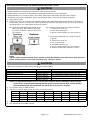
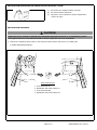
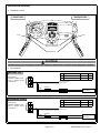
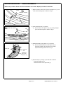
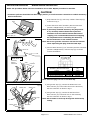
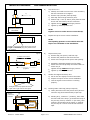
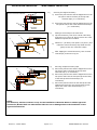
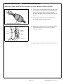
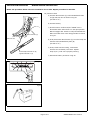
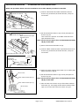
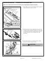
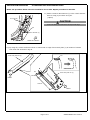
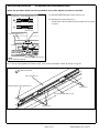
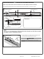
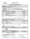
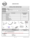
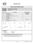
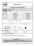
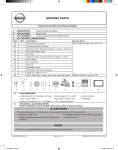
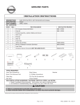
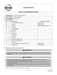
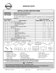
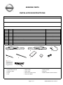
GENUINE PARTS
INSTALLATION INSTRUCTIONS
DESCRIPTION:
APPLICATION:
Illuminated Kick Plate
VERSA
PART NUMBER:
999G6 4Z000
KIT CONTENTS:
Item
A
B
C
D
E
F
G
H
I
J
Qty.
1
1
2
6
2
4
4
4
1
(2)
Part Description
Service Part Number
999G6 4Z010
999G6 4Z020
999G6 4Z030
N/A
N/A
N/A
N/A
EX-130RR
999V2 AW000
999Q9-AY000
Illuminated Kick Plate RH
Illuminated Kick Plate LH
Wire Harness
Tie Wrap
Long Tie Wrap
Gray Urethane Foam Tape
Black Urethane Foam Tape
Posi Tap
Installation Instructions Replacement Template
Accessory Service Connector (NOT INCLUDED IN KIT)
A
B
D
I
E
F
C
G
H
J
TOOLS REQUIRED:
●
●
●
●
Nylon Removal Tool
Masking Tape
Ruler
File
●
●
●
●
Wire Cutter
Flash Light
Soft non Linting Towel
Soap and Water
Page 1 of 17
● 10mm Socket
● Scissors
● 50/50 alcohol & water solution
999G6-4Z000 II Rev. 01/15/13
INSTALLATION PROCEDURE: PRE-INSTALLATION CAUTIONS / NOTES
CAUTION
● Dealer Installation Recommended. Instructions refer to Service Manual.
● Please read this instruction carefully before installing this product for correct installation.
● Please DO NOT use or install the part in ways other than what is described in this instruction manual.
● If problem occurs during installation, please contact Nissan dealer where you purchased the product.
1) Apply parking brake
2) Confirm the vehicle is no longer in the default shipping state (Extended Storage Switch Pulled Up and BCM in
Transit Mode). Failure to confirm the vehicle has been removed from this state will result in the loss of normal
vehicle operation. The confirmation requires two checks:
2a) Locate the Extended Storage Switch in the
cabin fuse block. Once located, check that
it is in the "Customer" position. See below
for reference.
Inventory
INCORRECT
2b) To remove transit mode is by doing as follows:
1. Remove fuse cover lid
2. Push down shorting pin
3. Ign On 2 times without turn the vehicle on
To put transit mode back is by doing as follows:
1. Ign Off
2. Remove fuse cover lid
3. Pull up shorting pin
4. Assemble fuse cover lid
5. Ign On 2 times without turn the vehicle on
6 Confirm transit mode condition on meter
CORRECT
INVENTORY - UP
NOTE:
Typical vehicle condition shown above. Switch is easily identifiable by the permanent, push-pull fuse
holder. Actual position on the fuse block may vary, vehicle to vehicle.
CAUTION
● Make sure the ignition is "OFF" before changing the switch position.
Condition
Vehicle is delivered to the dealer
Technician performs PDI
Customer test drives the vehicle
Vehicle is being stored at the dealer
Vehicle is sold and delivered to customer
Switch Position
Inventory Condition
Customer Delivery
Customer Delivery
Inventory Condition
Customer Delivery
Note
Turn switch back to Inventory position after PDI.
Turn switch back to Inventory position after test drive.
NOTE: The Extended Storage Switch is only an aid to improve battery life during vehicle storage
at the dealer. If the Extended Storage Switch fuse ever needs service after vehicle delivery,
discard the Extended Storage Switch and install the correct fuse in its place.
3)
4)
5)
6)
Turn ignition switch to "ON" position
Record the customer radio presets and other presets as required
Preset
1
2
3
4
5
6
Put shift lever in "P" position for A/T and CVT or "1st" for M/T
Turn ignition switch to "OFF" position
Page 2 of 17
999G6-4Z000 II Rev. 01/15/13
INSTALLATION PROCEDURE: PRE-INSTALLATION CAUTIONS / NOTES
Fig. 1
7)
Disconnect the negative battery terminal.
Use
seat and floor protection.
8)
9) This part is to be installed at surface temperature
of 65-100 deg.F.
INSTALLATION OVERVIEW:
CAUTION
● Take care not to scratch or damage any component during the removal or re-installation process.
● Trim pieces found to have witness marks or broken clips are not to be reinstalled.
1)
Remove the following vehicle parts in the sequence shown below. Store these re-usable parts
in a safe and protected manner.
Fig. 2
2
4
1
Removal Sequence
1.
2.
3.
4.
Inner Kick Plate
Dashboard Side
Inner Kick Plate
Dashboard Side
3
LH
Lower Panel LH
RH
Lower Panel RH
Page 3 of 17
999G6-4Z000 II Rev. 01/15/13
INSTALLATION OVERVIEW:
2)
Installation Outline
Fig. 3
Driver's side
Passenger's side
Fuse
Fuse
Connect to Accessory
Service Connector
Wire harness
CAUTION
● Vehicle wiring color description is just for reference. Please refer to vehicle wiring diagram for details.
3)
Mechanization
DRIVER'S SIDE
1
ACCE SSORY
SERVICE CONNEC TOR
(Part # ; 999Q9 -AY000)
TH12F W-NH
2
Signal
Battery Saver
Room lamp Output
Size
0.5
0.5
Room lamp output
2
Battery saver
1
0.5R
FUSE 3A
Illumination unit
(Kick Plate)
0.5W
PASSENGER'S SIDE
1
ACCE SSORY
SERVICE CONNEC TOR
(Part # ; 999Q9 -AY000)
TH12F W-NH
Color
Pink
Yellow
2
Signal
Battery Saver
Room lamp Output
Color
Pink
Yellow
Size
0.5
0.5
Room lamp output
2
Battery saver
1
0.5R
FUSE 3A
Illumination unit
(Kick Plate)
0.5W
Page 4 of 17
999G6-4Z000 II Rev. 01/15/13
INSTALLATION PROCEDURE:
VEHICLE PARTS REMOVAL
NOTE: The procedure below show the installation for LH side. Repeat procedure for RH side.
Fig. 4
45mm
45mm
1) Measure 45mm from front of Inner Kick plate LH (1) and
mark with masking tape as shown in Fig.4.
FRONT OF VEHICLE
Masking tape
Inner Kick plate LH (1)
Fig. 5
2) Inner Kick plate LH (1) removal
a) Remove Inner Kick plate LH (1) by pulling straight
up to disconnect clips as shown in Fig.5.
Fig. 6
3) Dashboard Side Lower panel LH (2) removal
a) Remove Dashboard Side Lower panel LH (2)
by pulling straight up to disconnect at metal
clips and locating hole shown in Fig.6.
FRONT OF VEHICLE
Inner Kick plate LH (1)
Metal clips
Locating
hole
Dashboard
Side Lower
panel LH (2)
4) Repeat steps 1) through 3) for RH side of vehicle.
Inner Kick plate RH (3)
Dashboard Side Lower panel RH (4).
Page 5 of 17
999G6-4Z000 II Rev. 01/15/13
INSTALLATION PROCEDURE:
WIRING HARNESS INSTALLATION
NOTE: The procedure below show the installation for LH side. Repeat procedure for RH side.
CAUTION
● Connector pull test should be less than 10kgf (22 lbs.) to confirm secure connection to vehicle Accessory
Service Connector
Fig.7
Fuse
Gray urethane
foam tape (F)
Fig.8
1) Wrap harness fuse (C) with Gray urethane foam tape (F)
as shown in Fig.7.
2) Locate the Driver side "Accessory Service Connector
(Part No. 999Q9-AY000") as shown in Fig.8.
Note: A previously installed accessory may be present.
If so, carefully remove the Accessory Service
Connector from the vehicle harness before Posi
-tapping. It is recommended that all Posi-tapping
be completed before reattaching the Accessory
Service Connector to the vehicle harness.
Note: Be sure to grab the connector and not the harness
when separating the plug from the foam tape.
3) Connect Wire harness (C) to "Accessory Service Connector
(Part No. 999Q9-AY000)" with Posi-Tap (H) as shown
in below Illustration.
View "A"
Tap position
Detail View "A"
Accessory
Service
Connector
Fuse
Signal
Color
Wire Harness
(C)
Color
Battery Saver
Room Lamp Output
PINK
YELLOW
RED
WHITE
Accessory Service Connector
Harness (C)
1
2
Note: See next page on how to use Posi tap.
Accessory service connector
Fig.9
Yellow wire
White wire
Service Connector as shown in Fig.9.
Shrink wrap
Pink wire
Shrink wrap
4) Using a Posi-Tap (H), connect the White wire from
Wire harness (C) to the Yellow wire on the Accessory
5) Using a Posi-Tap (H), connect the Red wire from
Wire harness (C) to the Pink wire on the Accessory
Service Connector as shown in Fig.9.
Note: Be sure NOT to Posi-Tap through the shrink wrap
tubing.
Red wire
Page 6 of 17
999G6-4Z000 II Rev. 01/15/13
INSTALLATION PROCEDURE:
WIRE HARNESS INSTALLTION
Fig. 10
6)
e)
d)
c)
b)
Accessory Service Connector
Tap vehicle wire.
a) Identify and confirm correct wire in the Accessory
Service Connector to be tapped.
b)
c)
d)
Remove cap (slot side) from tap body.
Slide cap around single accessory wire.
Position cap ≥ 0.25" (6.35mm) away from the heat
shrink end of Accessory Service Connector.
e)
f)
Tighten the tap TIGHT with finger pressure.
Tighten by another quarter turn.
NOTE:
Figures are not to scale. Do not re-use the tap.
Fig. 11
7)
Inspect the tap to ensure correct installation.
NOTE:
Avoid putting pressure on the vehicle wire and
tap for the remainder of the installation.
i. Straight and evenly spaced all the way around
ii. Tight and minimize gap (wire jacket should
be crushed)
Fig.12
8)
e) Insert wire to here
c)
a)
d)
f) Tighten
Fig. 13
i. Straight and evenly spaced all around
ii. Tight and no gap and test the signal
Service
Connector
Harness
Fig. 14
a)
b)
Tap accessory wire.
a) Remove tap (non-pierce) side from tap.
b) Remove the protective stub from the wire.
c) Insert wire through the non-pierce side opening.
d)
e)
Spread the individual strands into fan shape.
Insert wire into the tap body and ensure that it is
all the way in.
f)
g)
Tighten the tap TIGHT with finger pressure.
Tighten by another quarter turn.
9)
Confirm the tapped accessory wire.
a) Pull on the wire lightly to ensure connection.
b) Inspect the tap to ensure correct installation.
c) Test the signal to ensure that it is working
properly.
10)
Forming strain relief loop (always required).
a) Gently bend the end of the pierced wire (where it
exits the cap) down towards body of posi-tap.
b)
1" (25.4mm)
Accessory
Harness
c)
1" (25.4mm)
Starting at b), measure 1" (25.4mm), then make
the first bend of the loop c) up toward the body of
the posi-tap, from b) measure 1" (25.4mm), then
make the second bend of the loop d) in towards
the posi-tap so it can be secured with electrical
tape.
d)
Reference: 999M1 NADS0
Page 7 of 17
999G6-4Z000 II Rev. 01/15/13
INSTALLATION PROCEDURE:
Service Connector Harness
a)
WIRE HARNESS INSTALLTION
11)
Fig. 15
Securing the tapped accessory.
a) Secure the pierced wire and the tapped wire on the
non-pierce side to the body of the tap with
electrical tape (≥ 2 revolutions).
b)
b)
Accessory
harness
Fig. 16
12)
a)
b)
c)
1"(25.4mm)
Secure the pierced wire and the tapped wire on the
non-pierce side to each other with electrical tape
(≥ 2 revolutions).
Putting a second tap on the same wire.
Tap first accessory, then form a strain relief loop
as shown in Fig 1 thru 5a. Do not secure wire until
additional tap has been installed
b)
Measure 1" (25.4mm) from point b) to point c) and
install the second accessory tap. Bend the wire
gently to form the "staircase" shape.
c)
After tapping the second accessory, form a strain
relief loop d) as shown in Fig 5a
a)
d)
a)
b)
Fig.17
13)
a)
b)
c)
c)
Securing multiple accessory taps.
Secure the pierced wire and the tapped wire on the
non-pierce side to the body of the tap with
electrical tape (≥ 2 revolutions).
Secure the pierced wire and the tapped wire on the
non-pierce side from the first posi-tap to the body
of the 2nd tap with electrical tape (≥ 2
revolutions).
Secure the pierced wire from the last tap and the
tapped wires from the non-pierced sides of each
tap to each other with electrical tape (≥ 2
revolutions).
NOTE:
The Accessory Service Connector is only for the installation of Genuine Nissan or Nissan approved
accessories, Nissan shall not otherwise be liable for loss or damages due to the installation of non
approved accessories.
Reference: 999M1 NADS0
Page 8 of 17
999G6-4Z000 II Rev. 01/15/13
INSTALLATION PROCEDURE:
WIRING HARNESS INSTALLATION
NOTE: The procedure below show the installation for LH side. Repeat procedure for RH side.
Fig.18
14) Cut one piece of Gray urethane foam tape (F) in half.
Then, Wrap the Posi-Taps with Gray Urethane foam
tape (F) to prevent rattle as shown in Fig.18.
Use other half piece of Gray urethane foam tape for
RH side.
15) Then plug the Accessory Service Connector into
the vehicle harness on the driver side.
Gray Urethane Foam Tape (F)
Fig.19
Long tie
wrap (E)
16) Attach fuse on Wire harness (C) to vehicle harness
at the position as shown in Fig.19, by Long tie
wrap (E). (1 place)
Vehicle
Harness
Fuse
Harness(C)
17) Repeat steps 1) through 16) for RH side of vehicle.
Page 9 of 17
999G6-4Z000 II Rev. 01/15/13
INSTALLATION PROCEDURE:
WIRING HARNESS INSTALLATION
NOTE: The procedure below show the installation for LH side. Repeat procedure for RH side.
Fig.20
18) Function check
a) Connect Wire harness (C) to Illuminated Kick Plate
LH (B) LED unit wire as shown in Fig.20.
(RH side is "A")
b) Connect battery.
Wire Harness (C)
LED unit wire
c) Check function. Confirm RH/LH "VERSA" text is
Illuminated when either door is in the open position.
Manual engage door switch to verify Illuminated Kick
Plate turns OFF when room lamp goes OFF as shown
in Fig.21.
d) If OK, disconnect Wire harness (C) from the lamp unit
harness of Illuminated Kick plate (B).
(RH side is "A").
e) If NG, check harness routing, connections
and LED unit to identify root cause. Repeat
steps a) to c) until unit is properly working.
Illuminated Kick Plate LH (B)
opposite
RH side is (A)
f) Disconnect battery as shown in Fig.22.
Fig.21
Fig.22
Page 10 of 17
999G6-4Z000 II Rev. 01/15/13
INSTALLATION PROCEDURE:
ILLUMINATED KICK PLATE INSTALLATION
NOTE: The procedure below show the installation for LH side. Repeat procedure for RH side.
1) Clean the Illuminated Kick Plate attachment area as
shown in Fig.23 with 50/50 alcohol & water, let dry for
30 seconds.
Fig.23
FRONT OF VEHICLE
Illuminated Kick Pate attachment area
Fig.24
FRONT OF VEHICLE
Black Urethane Foam Tape
attachment area
A
2) Set Illuminated Kick Plate LH (B) to body side panel as
shown in Fig.24.
Then confirm the position of the Black Urethane Foam
Tape attachment area.
Note: Do Not remove tape's liner of Illuminated Kick Plate
LH (B) at this time.
3) Remove Illuminated Kick Plate LH (B).
A
Align to Masking tape
4) Clean the Black Urethane Foam Tape attachment area as
shown in Fig.24 with 50/50 alcohol & water, let dry for
30 seconds.
Illuminated Kick Plate LH (B)
15mm
(Reference)
SECTION A-A
Illuminated
Kick Plate LH (B)
Illuminated Kick Plate LH (B)
Fig.25
5) Attach the Black Urethane Foam Tape (G) to vehicle panel
flange as shown in Fig.25.
LED unit wire
Black urethane foam tape (G)
Black urethane foam tape (G)
LED Unit Wire
6) Set Illuminated Kick Plate LH (B) to body side panel as
shown in Fig.24.
Note: Do Not remove tape's liner of Illuminated Kick Plate
LH (B) at this time.
7) Place the LED unit harness on top of the Black Urethane
Foam Tape (H), then apply another Black Urethane foam
Tape (G) on top of the harness as shown in Fig.25.
Vehicle Panel of Flange
Page 11 of 17
999G6-4Z000 II Rev. 01/15/13
INSTALLATION PROCEDURE:
ILLUMINATED KICK PLATE INSTALLATION
NOTE: The procedure below show the installation for LH side. Repeat procedure for RH side.
Fig.26
FRONT OF VEHICLE
8) Route LED unit wire of Illuminated Kick plate LH (B) into
harness protector as shown in Fig.26.
Illuminated Kick plate LH (B)
Harness protector
LED unit wire
Illuminated Kick plate LH (B)
Fig.27
LED unit wire
Wire Harness (C)
9) Connect LED unit wire (B) to Wire harness (C) then cut
one piece of Gray Urethane Foam Tape (F) in half, apply
one half around connecting section as shown in Fig.27.
Use other half piece of Gray Urethane Foam Tape
for RH side.
Gray urethane foam tape (F) (half cut)
Fig.28
Connector
10) Secure Wire harness (C) to vehicle harness with Tie
wrap (D) as shown in Fig.28. (2 place)
Wire
Harness (C)
CAUTION
● Do not attach the harness to sharp metal edge.
Tie wrap (D)
FRONT OF VEHICLE
Page 12 of 17
999G6-4Z000 II Rev. 01/15/13
INSTALLATION PROCEDURE:
ILLUMINATED KICK PLATE INSTALLATION
NOTE: The procedure below show the installation for LH side. Repeat procedure for RH side.
11) Attach excessive Wire harness (C) to the vehicle harness
with Tie wrap (D) as shown in Fig.29.
(1 place)
Fig.29
Tie wrap (D)
CAUTION
● Do not attach the harness to sharp metal edge.
Wire Harness (C)
FRONT OF VEHICLE
12) By using file, remove surface as shown in section B-B on edge of Inner Kick plate (1) at location of 120mm
from front end as shown in Fig.30.
Fig.30
File
Inner Kick plate LH (1)
SECTION B-B
B
B
Inner Kick plate LH (1)
35mm
FRONT
120mm
FRONT
Page 13 of 17
999G6-4Z000 II Rev. 01/15/13
INSTALLATION PROCEDURE:
ILLUMINATED KICK PLATE INSTALLATION
NOTE: The procedure below show the installation for LH side. Repeat procedure for RH side.
Inner Kick Plate LH (1)
Filed area
LED wire
Fig.31
13) Reinstall Dashboard Side Lower panel LH (2)
14) Reinstall Inner Kick Plate LH (1).
At that time route the LED unit wire to filed area as shown
in Fig.31.
Sill Panel
LED unit wire
Inner Kick Plate LH (1)
LED unit wire
Illuminated Kick Plate LH (B)
FRONT OF VEHICLE
15) Turn up Illuminated Kick Plate LH (B), then remove all tape's liners as shown in Fig.32.
Fig.32
FRONT OF VEHICLE
Inner Kick Plate (1)
Dashboard Side Lower panel LH (2)
Tape's liners
Illuminated Kick Plate LH (B)
Tape's liners
Page 14 of 17
999G6-4Z000 II Rev. 01/15/13
INSTALLATION PROCEDURE:
ILLUMINATED KICK PLATE FRONT INSTALLATION
NOTE: The procedure below show the installation for LH side. Repeat procedure for RH side.
16) Align Illuminated Kick Plate LH (B) to masking tape and Inner Kick Plate (1) as shown in Fig.33.
FRONT OF VEHICLE
Fig.33
Inner Kick Plate LH (1)
D
D
Illuminated Kick Plate LH (B)
DETAIL C
SECTION D-D
Illuminated Kick Plate LH (B)
Masking tape
NOTE:
Make sure no visual gap between Illuminated Kick Plate (B) and Inner Kick Plate (1) plastic
trim edge as shown in SECTION D-D Fig.33.
FRONT OF VEHICLE
Fig.34
17) Apply minimum 11lb (49N) of pressure along the part
to secure tape to body as shown in Fig.34.
CAUTION
Press bond
● Use caution when applying pressure as the surface
may dent.
Page 15 of 17
999G6-4Z000 II Rev. 01/15/13
ACCESSORY CHECK: (Must for any accessory that uses the vehicle battery for power)
Connect the battery negative terminal and tighten the nut to 5.4 N-m (47.8 lb-in)
Check all Critical Installation Steps.
Check all torque values. (Reference related steps and figures)
Verify all wiring is secure and not exposed.
Trim all excess cable ties flush.
Check function. Confirm RH/LH "VERSA" text is Illuminated when either door is in the open
position. Manual engage door switch to verify Illuminated Kick plate turns OFF when room lamp
goes OFF
Check all vehicle electrical systems that the accessory interfaces with.
Vehicle electrical system 1 (Must for pre-wiring, overlay harness, and Posi-Tap)
Vehicle electrical system 2 (Electrical system(s) that the accessory connects to)
RE-INSTALLATION OF REMOVED PARTS:
Re-install all removed vehicle parts. Refer to the vehicle service manual as necessary.
CAUTION
Use caution when re-installing interior components to avoid damage, scratches, or breaking of mounting
clips. Refer to the vehicle service manual for more information.
Clean interior of vehicle.
Page 16 of 17
999G6-4Z000 II Rev. 01/15/13
FINAL INSPECTION:
Verify re-installed trim parts for proper flush fit (no gap, no waviness, etc.).
Verify all clips are fully engaged and locked.
Verify re-installed trim parts are free from cracks, scratches or stress marks.
Verify vehicle headliner, seat, steering wheel, center console, floor carpets, etc. are not soiled.
Verify interior and exterior is not damaged.
Turn ignition switch to "ON" and confirm proper operation of Vehicle Systems
If equipped, verify all window and sunroof one touch operation and perform the reset procedure if
necessary. Refer to the vehicle service manual for more details.
Confirm proper audio function (AM, FM, SAT, CD and AUX).
Start engine and verify that there are no new Diagnostic Trouble Code. Turn ignition switch to "OFF".
Place the Owner Manual, Quick Reference Guide, and/or other Manual in the glove box.
If this vehicle will be returned to a dealer lot or showroom for an extended period of time, be sure the
extended storage switch is placed in the "inventory" position. Refer to the Extended Storage Switch verbiage at
the beginning of the 'INSTALLATION PROCEDURE' section.
Re-program radio presets and other vehicle settings to the recorded settings. No need to do this step if the
extended storage switch is placed in the "inventory" position.
CAUTION
● Do NOT step on kick plate and wash vehicle for 24 hours after installing to prevent the double-sided
tapes from peeling.
● When turn off the ignition switch, do NOT let the door opening for long time, or else electrical source
can be used up.
NOTE:
Posi-TapTM is protected by patent # 5,228,875 5,695,369 5,868,589 6,692,313 Jap 2881414 Aus
708700 Tia 103534 Can 2204826 Mex 200626 Korea 477279 China Z197105562.9 & others pending.
Page 17 of 17
999G6-4Z000 II Rev. 01/15/13