1
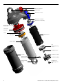
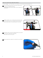
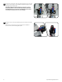
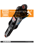
Monarch Plus RC3/R Service Manual GEN.0000000004938 Rev A © 2015 SRAM, LLC SRAM LLC WARRANTY EXTENT OF LIMITED WARRANTY Except as otherwise set forth herein, SRAM warrants its products to be free from defects in materials or workmanship for a period of two years after original purchase. This warranty only applies to the original owner and is not transferable. Claims under this warranty must be made through the retailer where the bicycle or the SRAM component was purchased. Original proof of purchase is required. Except as described herein, SRAM makes no other warranties, guaranties, or representations of any type (express or implied), and all warranties (including any implied warranties of reasonable care, merchantibility, or fitness for a particular purpose) are hereby disclaimed. LOCAL LAW This warranty statement gives the customer specific legal rights. The customer may also have other rights which vary from state to state (USA), from province to province (Canada), and from country to country elsewhere in the world. To the extent that this warranty statement is inconsistent with the local law, this warranty shall be deemed modified to be consistent with such law, under such local law, certain disclaimers and limitations of this warranty statement may apply to the customer. For example, some states in the United States of America, as well as some governments outside of the United States (including provinces in Canada) may: a.Preclude the disclaimers and limitations of this warranty statement from limiting the statutory rights of the consumer (e.g. United Kingdom). b.Otherwise restrict the ability of a manufacturer to enforce such disclaimers or limitations. For Australian customers: This SRAM limited warranty is provided in Australia by SRAM LLC, 1333 North Kingsbury, 4th floor, Chicago, Illinois, 60642, USA. To make a warranty claim please contact the retailer from whom you purchased this SRAM product. Alternatively, you may make a claim by contacting SRAM Australia, 6 Marco Court, Rowville 3178, Australia. For valid claims SRAM will, at its option, either repair or replace your SRAM product. Any expenses incurred in making the warranty claim are your responsibility. The benefits given by this warranty are additional to other rights and remedies that you may have under laws relating to our products. Our goods come with guarantees that cannot be excluded under the Australian Consumer Law. You are entitled to a replacement or refund for a major failure and for compensation for any other reasonably foreseeable loss or damage. You are also entitled to have the goods repaired or replaced if the goods fail to be of acceptable quality and the failure does not amount to a major failure. LIMITATIONS OF LIABILITY To the extent allowed by local law, except for the obligations specifically set forth in this warranty statement, in no event shall SRAM or its third party suppliers be liable for direct, indirect, special, incidental, or consequential damages. LIMITATIONS OF WARRANTY This warranty does not apply to products that have been incorrectly installed and/or adjusted according to the respective SRAM user manual. The SRAM user manuals can be found online at sram.com, rockshox.com, avidbike.com, truvativ.com, or zipp.com. This warranty does not apply to damage to the product caused by a crash, impact, abuse of the product, non-compliance with manufacturers specifications of usage or any other circumstances in which the product has been subjected to forces or loads beyond its design. This warranty does not apply when the product has been modified, including, but not limited to any attempt to open or repair any electronic and electronic related components, including the motor, controller, battery packs, wiring harnesses, switches, and chargers. This warranty does not apply when the serial number or production code has been deliberately altered, defaced or removed. This warranty does not apply to normal wear and tear. Wear and tear parts are subject to damage as a result of normal use, failure to service according to SRAM recommendations and/or riding or installation in conditions or applications other than recommended. Wear and tear parts are identified as: •Dust seals •Bushings •Air sealing o-rings •Glide rings •Rubber moving parts •Foam rings •Rear shock mounting hardware and main seals •Upper tubes (stanchions) •Stripped threads/bolts (aluminium, titanium, magnesium or steel) •Brake sleeves •Brake pads •Chains •Sprockets •Cassettes •Shifter and brake cables (inner and outer) •Handlebar grips •Shifter grips •Jockey wheels •Disc brake rotors •Wheel braking surfaces •Bottomout pads •Bearings •Bearing races •Pawls •Transmission gears •Spokes •Free hubs •Aero bar pads •Corrosion •Tools •Motors •Batteries Notwithstanding anything else set forth herein, the battery pack and charger warranty does not include damage from power surges, use of improper charger, improper maintenance, or such other misuse. This warranty shall not cover damages caused by the use of parts of different manufacturers. This warranty shall not cover damages caused by the use of parts that are not compatible, suitable and/or authorised by SRAM for use with SRAM components. This warranty shall not cover damages resulting from commercial (rental) use. Table of Contents Exploded View - Monarch Plus™ RC3/R Rear Shock.................................................................................................................... 4 Maintenance........................................................................................................................................................................................ 5 RockShox Suspension Service......................................................................................................................................................... 6 Mounting Hardware and Bushing Service...................................................................................................................................... 6 Parts and Tools for Mounting and Bushing Service................................................................................................................................................................ 6 Mounting Hardware Removal........................................................................................................................................................................................................... 6 Eyelet Bushing Replacement............................................................................................................................................................................................................ 8 Mounting Hardware Installation.....................................................................................................................................................................................................10 Monarch Plus™ RC3/R Service.........................................................................................................................................................12 Parts and Tools Needed For Service............................................................................................................................................................................................ 12 Air Can Removal.................................................................................................................................................................................................................................... 12 Air Can Service...................................................................................................................................................................................................................................... 15 Damper Body Service.........................................................................................................................................................................................................................18 Piston Service.........................................................................................................................................................................................................................................19 IFP Reservoir Service.........................................................................................................................................................................................................................24 Reassembly and Bleed...................................................................................................................................................................................................................... 28 Air Can Installation.............................................................................................................................................................................................................................. 35 SAFETY FIRST! We care about YOU. Please, always wear your safety glasses and protective gloves when servicing RockShox products. Protect yourself! Wear your safety gear! Exploded View - Monarch Plus™ RC3/R Rear Shock Rebound Adjuster Shaft Eyelet Compression Lever Compression Needle Compression Assembly Bottom Out Washer and O-ring Seal Head/ Air Piston Shaft IFP Reservoir Main Piston Damper Body IFP (Internal Floating Piston) IFP Bleed Screw Air Can IFP Reservoir Cap Damper Body Bleed Screw IFP Retaining Ring Damper Body Eyelet 4 IFP Reservoir Air/Nitrogen Fill Cap Exploded View - Monarch Plus™ RC3/R Rear Shock Maintenance To maintain the high performance, safety, and long life of your rear suspension, it is required that you periodically check the fastener torque values for compliance as well as perform routine maintenance on your shock. If you ride in extreme conditions, torque compliance checks and maintenance should be performed more frequently. MAINTENANCE INTERVAL (hours) Refer to bicycle’s owner’s manual for correct mounting hardware torque values* 8 Clean your shock with mild soap and a toothbrush 8 Keep mounting hardware clean and lubricated 8 Remove, clean, and grease mounting hardware 20 Inspect eyelet bushings and mounting hardware for wear and play. Replace if necessary 100 or annually Inspect shaft, reservoir, damper body and air can for scratches or damage (if applicable). Replace if necessary 100 or annually Replace all seals 100 or annually Replace damping fluid (if applicable) 100 or annually WARNING Before disassembly or service of any air system remove the air pressure from all air chambers and remove the air valve cores. For complete service instructions, visit www. sram.com or www.rockshox.com. If your shock will not return to full extension, do not attempt to service or disassemble your shock. Attempting to service a shock that will not return to full extension can cause severe and/or fatal injuries. 5 Maintenance RockShox Suspension Service We recommend that you have your RockShox suspension serviced by a qualified bicycle mechanic. Servicing RockShox suspension requires knowledge of suspension components as well as the special tools and fluids used for service. For exploded diagram and part number information, please refer to the Spare Parts Catalog available on our web site at www.sram.com/service. For order information, please contact your local SRAM distributor or dealer. Information contained in this publication is subject to change at any time without prior notice. For the latest technical information, please visit our website at sram.com/service. Your product‘s appearance may differ from the pictures/diagrams contained in this publication. Mounting Hardware and Bushing Service Prior to servicing the rear shock, remove it from the bicycle frame according to the bicycle manufacturer's instructions. Once the shock is removed from the bicycle, remove the mounting hardware before performing any service. N OT I C E To prevent damage to the shock use aluminum soft jaws and position the eyelet in the vise so that the adjustment knobs are clear of the vise jaws. To ensure proper performance, always grease all o-rings before installation with RockShox Dynamic Seal Grease P a r t s a n d To o l s f o r M o u n t i n g a n d B u s h i n g S e r v i c e • • • • • Safety glasses Nitrile gloves Apron Clean, lint-free rags Suspension specific grease • • • • Bench vise with aluminum soft jaws RockShox 1/2" x 1/2" rear shock bushing removal/installation tool 13 mm open end wrench Adjustable wrench Mounting Hardware Removal Some mounting hardware is easily removed using only your fingers. Try to remove the end spacers with your fingernail, then push the bushing pin out of the bushing. If this works, move on to the next section, Eyelet Bushing Replacement. If you are unable to remove the mounting hardware using your fingers, use the RockShox rear shock bushing removal/installation tool. Push pin Catcher Threaded rod Rear shock bushing installation/removal tool 1 6 Thread the small end of the push pin onto the threaded rod until the rod is flush or slightly protrudes from the hex-shaped end of the push pin. RockShox Suspension Service 2 Insert the threaded rod through the shaft eyelet until the push pin rests against the bushing pin. Thread the large, open end of the catcher along the rod until it rests on the end spacer. 3 Clamp the catcher in a vise or hold it secure with a 13 mm open end or adjustable wrench. Use a second 13 mm wrench to thread the push pin along the rod until it stops against the end spacer. Unthread the push pin from the threaded rod and remove the end spacer from that side. NOTIC E Do not scratch the air can as you turn the wrench. 13 mm 4 13 mm Reinsert the threaded rod and push pin through the shaft eyelet. Thread the large, open end of the catcher along the rod until it rests against the shaft eyelet. Use a 13 mm wrench to thread the push pin along the rod until it stops against the end spacer. 13 mm 5 13 mm Unthread the catcher from the threaded rod. Remove the end spacer and bushing pin from the tool. Set the mounting hardware aside until you have finished servicing your shock. Repeat for the body eyelet. 7 Mounting Hardware Removal Eyelet Bushing Replacement To replace damaged or worn out bushings, use the RockShox rear shock bushing removal/installation tool. 1 Insert the threaded rod through the shaft eyelet until the base of the push pin rests against the bushing. Thread the large, open end of the catcher onto the rod until it rests on the eyelet. 2 Clamp the catcher in a vise or hold it secure with a 13 mm wrench. Use a second 13 mm wrench to thread the push pin along the rod until the push pin pushes the eyelet bushing out of the eyelet. 13 mm 3 13 mm Unthread the catcher from the threaded rod. Remove the tool from the shaft eyelet and discard the old bushing. Repeat steps 1-3 for the other eyelet. 4 8 Apply a small amount of grease to the outside of the new bushing. Eyelet Bushing Replacement 5 Position the shaft eyelet and eyelet bushing between the soft jaws of a vise. Slowly turn the vise handle to begin pressing the eyelet bushing into the shaft eyelet. Check the alignment of the bushing as it enters the eyelet. If the bushing starts to enter the eyelet at an angle, remove the bushing from the eyelet, regrease the bushing, and repeat this step until the bushing enters the eyelet straight. 6 Continue to press the eyelet bushing until it is seated in the shaft eyelet. Remove the shock from the vise and repeat the installation process for the other bushing and eyelet. 9 Eyelet Bushing Replacement Mounting Hardware Installation Some mounting hardware is easily installed using only your fingers. Press the bushing pin into the shock eyelet bushing until the pin protrudes from both sides of the eyelet an equal amount. Next, press an end spacer, large diameter side first, onto each end of the bushing pin. If this works, you have completed mounting hardware and bushing service. If you are unable to install your mounting hardware using your fingers, use the RockShox rear shock bushing removal/installation tool. 1 Thread the small end of the push pin onto the threaded rod until the push pin is flush or slightly protrudes from the hex-shaped end of the push pin. 2 Insert the threaded rod through the bushing pin then through the shaft eyelet so that the bushing pin is positioned between the push pin and the eyelet. 3 Thread the large, open end of the catcher onto the rod until it rests on the eyelet. 10 Mounting Hardware Installation 4 Clamp the catcher in a vise or hold it secure with a 13 mm wrench. Use a second 13 mm wrench to thread the push pin along the rod until it pushes the bushing pin into the shock eyelet bushing. Continue to thread the push pin until the bushing pin protrudes from both sides of the eyelet an equal amount. You may need to unthread the catcher slightly to check the bushing pin spacing. 13 mm 5 Unthread the catcher from the threaded rod and remove the tool from the shaft eyelet. 6 Press an end spacer, large diameter side first, onto each end of the bushing pin. 11 Mounting Hardware Installation Monarch Plus™ RC3/R Service Prior to servicing your rear shock, remove it from the bicycle frame according to the bicycle manufacturer's instructions. Once the shock is removed from the bicycle, remove the mounting hardware before performing any service (see the Mounting Hardware And Bushing Service section). P a r t s a n d To o l s N e e d e d F o r S e r v i c e • • • • • • • • • • • • • Safety glasses Nitrile gloves Apron Clean, lint-free rags Oil pan Isopropyl alcohol RockShox Dynamic Seal Grease Suspension specific grease Maxima® Maxum4 Extra 15w50 lube RockShox 3wt suspension fluid Bench vise with aluminum soft jaws RockShox Rear Shock Vise Block Monarch air fill adapter • • • • • • • • • • • • Torque wrench 12 mm socket wrench 13, 17, and 27 mm open end wrench 13, 17, and 27 mm crowfoot wrench 1.5 and 2 mm hex wrenches T10 TORX® wrench and bit socket 5 inch socket extension Schrader valve core tool Strap wrench Pick Shock pump Metric caliper or small metric ruler SAFETY INSTRUCTIONS Wear safety glasses and nitrile gloves when working with suspension fluid. Place an oil pan on the floor underneath the area where you will be working on the shock. NOTIC E Do not scratch any sealing surfaces when servicing your suspension. Scratches can cause leaks. When replacing o-rings, use your fingers or a pick to remove the o-ring. Clean the o-ring groove and apply grease to the new o-ring. To prevent damage to the shock use aluminum soft jaws and position the eyelet in the vise so that the adjustment knobs are clear of the vise jaws. Your product's appearance may differ from the pictures/diagrams contained in this publication. Air Can Removal 1 To record your adjustment settings, turn the rebound adjuster knob counter-clockwise (toward the rabbit) until it stops, while counting the number of detent clicks. This will assist you with post-service set up. Monarch Plus RC3 Only: Turn the compression lever to the unlocked (min) position. 12 Monarch Plus™ RC3/R Service 2 Record your air pressure setting to assist with post-service set up. Remove the air valve cap by hand. Use a small hex wrench to depress the Schrader valve and release all air pressure from the air can. Use a Schrader valve tool to remove and replace the valve core from the valve body. CAUTION - E YE HAZARD Do not disassemble a pressurized shock, this can cause suspension fluid or debris to forcefully eject from the shock. Wear safety glasses. 3 Use a Schrader valve tool to remove the IFP reservoir valve cap. Use a small hex wrench or pick to depress the Schrader valve and release all air pressure from the IFP reservoir. Once the pressure has been released, depress the Schrader valve a second time. If the Schrader valve is able to move, the shock has been completely depressurized. If the Schrader valve does not move at all, the shock is still pressurized and will need to be sent to an authorized RockShox service center for further service. CAUTION - E YE HAZARD Verify all pressure is removed from the shock before proceeding. Failure to do so can cause the damper body to separate from the shaft eyelet at a high velocity. Wear safety glasses. Do not remove the damper body bleed screw from the damper body eyelet until instructed to do so. Removing the damper body bleed screw while the shock is pressurized will result in fluid being forcefully ejected from the bleed port. Wear safety glasses. 13 Air Can Removal 4 Use a Schrader valve tool to remove and replace the Schrader valve core from the IFP reservoir valve. 5 Clamp the shaft eyelet into a vise, with the shock positioned horizontally. 6 If the shock is collapsed so that a minimal amount of damper body is visible, there is still air pressure in the air can. Insert a rag through the damper body eyelet. This will prevent the air can from forcefully ejecting from the shock upon disassembly. CAUTION - E YE HAZARD Do not disassemble a pressurized shock, this can cause suspension fluid or debris to forcefully eject from the shock. Wear safety glasses. 7 Use a strap wrench to remove the air can. Wrap the strap around the section of the air can furthest from the shaft eyelet. Turn the wrench counter-clockwise to unthread the air can. Once it is completely unthreaded, slowly pull the air can along the damper body to remove it. Do not place the strap wrench on the air can decal. High Volume Air Cans: Grip the lower portion of the can; otherwise, the high volume sleeve will rotate independent of the air can. DebonAir TM Air Cans: Remove the sleeve retaining o-ring and the outer sleeve. Clean the air can sleeve. Place a strap wrench on the air can. Turn the strap wrench counter-clockwise to remove the air can. Be careful not to damage seal glands with the strap wrench. Vacuum pressure will increase as you pull the air can along the damper body, then suddenly release as the end of the can comes over the damper body eyelet. 14 Air Can Removal Air Can Service NOTIC E Do not scratch any sealing surfaces when servicing your suspension. Scratches can cause leaks. When replacing seals and o-rings, use your fingers or a pick to remove the seal or o-ring. Clean the groove and apply RockShox Dynamic Seal Grease to the new seal or o-ring. 1 Use a pick to pierce and remove the air can dust wiper seal located in the top groove. Use a pick to pierce and remove the quad seal located between the two backup rings in the second deepest groove. 2 Use a pick to remove the two backup rings from the second deepest groove inside the air can. 3 Spray isopropyl alcohol inside the air can and clean it with a rag. Remove a glove and use your finger to inspect the inside and outside of the air can for scratches, dents, or other surface deformations. Replace the air can if it is scratched or damaged. All air cans have a small dimple, as seen from the exterior of the can, and high volume air cans have a small port inside the high volume sleeve that you should feel. 4 15 Install the first backup ring by inserting one end into the air can, then push the remainder of the ring into the can, so that it rests on the bottom of the second deepest groove. Air Can Service 5 Apply a small amount of RockShox Dynamic Seal Grease to the new quad seal and install it above the backup ring in the second deepest groove. 6 Install the second backup ring by inserting one end into the air can, then push the remainder of the ring into the can, so that it rests on the quad seal at the top of the second deepest groove. 7 Orient the new dust wiper seal step side up. Install it into the dust wiper seal groove at the top of the air can. 8 Spray isopropyl alcohol on the air can threads and eyelet body threads and clean them with a rag. Apply a small amount of RockShox Dynamic Seal Grease to the quad seal, backup rings, and dust wiper seal. Set the air can aside. 16 Air Can Service 9 High Volume Air Cans: Remove the retention o-ring from the high volume sleeve. Firmly grip the high volume sleeve and slide it off of the air can. 10 High Volume Air Cans: Use your fingers to remove and replace the high volume sleeve o-rings. DebonAir TM Air Cans: Use your fingers to remove and replace the three o-rings. Spray isopropyl alcohol inside the high volume sleeve and clean it with a rag. DebonAir 11 High Volume Air Cans: Apply a small amount of suspension specific grease to the inside of the sleeve. This stops the o-rings from rolling as the sleeve slides over them. Slide the sleeve onto the air can. Install the high volume sleeve retention o-ring into the groove outside of the air can. DebonAir TM Air Cans: Leave the sleeve off until after the air can has been installed and torqued. 17 Air Can Service Damper Body Service NOTIC E Use aluminum soft jaws to protect the damper body eyelet when clamped. Do not scratch any sealing surfaces when servicing your suspension. Scratches can cause leaks. When replacing seals and o-rings, use your fingers or a pick to remove the seal or o-ring. Clean the groove and apply grease to the new seal or o-ring. 1 Remove and replace the top out bumper on the damper body. 2 Use a 17 mm open end wrench to loosen the seal head/air piston assembly from the damper body. Use your hand to remove the assembly. Fluid will spill from the assembly. 17 mm 3 18 Remove the damper body from the vise and pour the fluid into an oil pan. Damper Body Service Piston Service NOTIC E Do not scratch any sealing surfaces when servicing your suspension. Scratches can cause leaks. When replacing seals and o-rings, use your fingers or a pick to remove the seal or o-ring. Clean the groove and apply RockShox Dynamic Seal Grease to the new seal or o-ring. 1 Spray isopropyl alcohol on the shaft assembly and clean it with a rag. 2 Slide the seal head/air piston toward the shaft eyelet until it stops. 3 Use the RockShox Rear Shock Vise Block to clamp the damper shaft into a vise. Do not remove the damper shaft from the eyelet. N OT I C E To prevent damage to the seal head/air piston, position the damper shaft in the vise so that the piston and IFP reservoir are clear of the vise jaws. 4 Use a 12 mm socket wrench to remove the main piston nut. 12 mm 19 Piston Service 5 Use a small wrench or pick to slide the main piston assembly off the damper shaft and onto the tool. Keep all the parts together and set them aside. NOTIC E If the shims are not in the correct order, the shock will not perform properly. 6 Remove the seal head/air piston from the damper shaft. 7 Use a pick to remove and replace the internal seal o-ring located in the internal seal gland. 8 Use a pick to remove and replace the inner o-ring, located at the base of the threads in the seal head/air piston. 20 Piston Service 9 Remove and replace the bottom out washer and o-ring from the damper shaft. 10 Use your fingers to remove and replace the o-ring located inside the shaft eyelet threads. 11 Install the seal head/air piston onto the damper shaft. 21 Piston Service 12 Use your fingers to remove and replace the seal head/air piston seal and glide rings. 13 Use the RockShox Rear Shock Vise Block to clamp the damper shaft into a vise. N OT I C E To prevent damage to the seal head/air piston, position the shaft in the vise so that the piston and IFP reservoir are clear of the vise jaws. 22 Piston Service 14 Install the main piston assembly that was removed in step 5 onto the damper shaft. To ensure the delta shim is centered, use your fingers to squeeze the shims and center the shim stack on top the main piston. Be sure to keep the main piston assembly parts in the same order. NOTIC E If the shims are not centered and in the correct order, the shock will not perform properly. 15 Apply 242® Blue Loctite® only on the threads of the nut, then thread the nut onto the damper shaft. Use a torque wrench with a 12 mm socket to tighten the main piston nut to 4.5 Nm (40 in-lb). 12 mm 4.5 N·m (40 in-lb) Remove the assembly from the vise. 23 Piston Service IFP Reservoir Service NOTIC E Use aluminum soft jaws to protect the damper body eyelet when clamped. Do not scratch any sealing surfaces when servicing your suspension. Scratches can cause leaks. When replacing seals and o-rings, use your fingers or a pick to remove the seal or o-ring. Clean the groove and apply grease to the new seal or o-ring. 1 Clamp the shaft eyelet into the vise. 2 Use a pick to remove the retention clip from the IFP reservoir. Use your thumb to push the IFP reservoir cap into the reservoir until it stops. CAUTION - E YE HAZARD The retention clip can eject rapidly as it is removed. Wear safety glasses. Do not scratch the inside of the IFP reservoir with the pick. 3 Thread the Monarch™ air valve adapter tool into a shock pump. Thread the pump and adapter into the IFP reservoir cap. Pull up on the pump and rock it side to side to remove the IFP reservoir cap from the IFP reservoir. Remove the IFP reservoir cap assembly from the pump/adapter. Inspect the IFP reservoir cap for damage. If it is damaged, it will need to be replaced. 24 IFP Reservoir Service 4 Remove and replace the IFP reservoir cap o-ring. 5 Use a 27 mm open end wrench at the base of the IFP reservoir to loosen it from the eyelet. Remove the shock from the vise, hold it over an oil pan, and turn the shock over to remove the IFP reservoir by hand. Fluid will spill from the IFP reservoir when it is removed. Pour the fluid into an oil pan. 27 mm 6 Monarch Plus™ RC3 Only: Use your fingers to remove the compression assembly from the IFP reservoir or eyelet. If the compression assembly is still installed in the eyelet, pull on the piston nut while rocking it from side to side to remove the compression assembly. 7 25 Monarch Plus RC3 Only: Remove and replace the compression assembly o-rings. IFP Reservoir Service 8 Use your fingers to remove and replace the o-ring located inside the eyelet threads. 9 Use your finger to push the IFP out of the IFP reservoir. 10 Use a T10 TORX® wrench to remove the IFP bleed screw. Replace the o-ring on the IFP bleed screw. Set the bleed screw aside. T10 11 26 Remove and replace the IFP o-ring. IFP Reservoir Service 12 Install the IFP, flat side up, into the IFP reservoir. Use a metric caliper or ruler to push the IFP into the reservoir to a depth of 35 mm. 13 Monarch Plus™ RC3 Only: Install the compression assembly, nut side first, into the threaded side of the IFP reservoir. Push the compression assembly into the reservoir until it stops. 35 mm Check that the compression lever is still in the unlocked (min) position and the compression needle is sticking up. 14 Thread the IFP reservoir onto the eyelet by hand. Use a torque wrench with 27 mm crowfoot to tighten the IFP reservoir to 8.4 N·m (75 in-lb). 27 mm 8.4 N·m (75 in-lb) Install the crowfoot onto the torque wrench at a 90° angle to the handle to ensure an accurate torque reading. 27 IFP Reservoir Service Reassembly and Bleed NOTIC E Use aluminum soft jaws to protect the damper body eyelet when clamped. Do not scratch any sealing surfaces when servicing your suspension. Scratches can cause leaks. When replacing seals and o-rings, use your fingers or a pick to remove the seal or o-ring. Clean the groove and apply grease to the new seal or o-ring. 1 Clamp the damper body eyelet into the vise. Wrap a clean rag around the damper body. 2 Pour new RockShox 3wt suspension fluid into the damper body until it is level with the top. 3wt 3 Check that the rebound adjuster is set to the minimum setting (toward the rabbit). Monarch RC3 Only: Check that the compression lever is set to the unlocked (min) position. Use a 1.5 mm hex wrench to push the compression needle up. This will ensure that there is a path for bleeding. Slide the seal head/air piston until it stops at the end of the damper shaft. 1.5 mm RC3 4 Use your hand to install the seal head/air piston onto the damper body. Do not hold on to the shaft eyelet or damper shaft while inserting the seal head. It will move the piston/shaft assembly, causing too much fluid to displace out of the damper body. 28 Reassembly and Bleed 5 Use a torque wrench with a 17 mm crowfoot to tighten the seal head/air piston to 28 N·m (248 in-lb). Install the crowfoot onto the torque wrench at a 90° angle to the handle to ensure an accurate torque reading. 17 mm 28 N·m (248 in-lb) 6 Remove the shock from the vise. Turn the shock over and clamp the shaft eyelet into the vise. 7 Slowly push the damper body downward. Fluid will begin to fill the reservoir through the IFP bleed port. Continue to push down until the damper body stops. CAUTION - E YE HAZARD Do not look directly into the reservoir as you push on the damper body. Fluid may be ejected from the IFP reservoir if you push the damper down to fast. Wear safety glasses. 8 Pour RockShox 3wt suspension fluid into the IFP reservoir until it is level with the top of the reservoir. 3wt 9 Slowly pull up on the damper body until it stops. This will cycle fluid from the reservoir back into the damper body and purge air bubbles from the system. Continue to pull up and push down on the damper body until no more air bubbles emerge from the IFP bleed port. 29 Reassembly and Bleed 10 Use a T10 TORX® wrench to install the IFP bleed screw into the IFP. The bleed screw should be submerged in fluid. T10 11 Use a T10 TORX wrench to remove the damper body bleed screw from the damper body eyelet. T10 12 Wrap a clean rag around the damper body. Slowly push down on the damper body to purge the air bubbles from the bleed port in the damper body eyelet. Stop pushing on the damper body when there are no more air bubbles. 13 30 If the damper body is all the way down and air bubbles are still present, then reinstall the damper bleed screw, remove the IFP bleed screw, and repeat steps 9-12 until no more air bubbles are present. Reassembly and Bleed 14 Replace the o-ring on the damper body bleed screw. Use a T10 TORX® wrench to install the damper body bleed screw into the damper body eyelet. Use a torque wrench with a T10 TORX bit socket to tighten the bleed screw to 1.1 N·m (10 in-lb). To ensure a good bleed, fluid should be displaced out of the bleed port. Spray isopropyl alcohol on the damper body and clean it with a rag. T10 1.1 N·m (10 in-lb) T10 15 Use a T10 TORX wrench to remove the IFP bleed screw from the IFP. T10 16 Pour additional RockShox 3wt suspension fluid into the IFP reservoir until it is level with the top of the reservoir. 3wt 31 Reassembly and Bleed 17 Slowly pull up on the damper body until it stops. 18 Use a T10 TORX® wrench to install the IFP bleed screw into the IFP. The bleed screw should be submerged in fluid. T10 19 Remove the shock from the vise. Pour the fluid out of the IFP reservoir. Spray isopropyl alcohol in the IFP reservoir and clean it with a rag. Clamp the shaft eyelet into the vise so the shock is vertical. 20 32 Use the Schrader valve tool to install a new Schrader valve into the IFP reservoir cap. Reassembly and Bleed 21 Apply a small amount of grease to the IFP reservoir cap o-ring. Push the IFP reservoir cap into the IFP reservoir until the retaining ring groove is visible. 22 Push the new retaining ring into the groove until it is seated. CAUTION - E YE HAZARD The retention clip can eject rapidly as it is removed. Wear safety glasses. 23 33 Thread the pump and Monarch™ air valve adapter tool into the IFP reservoir cap. Pull up on the pump to seat the reservoir cap against the retaining ring. Reassembly and Bleed 24 Use the pump to pressurize the IFP reservoir to 250 psi. Once you have pressurized the reservoir, remove the Monarch air valve adapter from the air fill port before removing it from the shock pump. Separating the pump from the adapter first will allow all of the air to escape from the reservoir. You may substitute nitrogen if you have the proper fill equipment. 250 psi 25 Remove and replace the IFP reservoir fill cap o-ring. Use a Schrader valve tool to install the fill cap into the IFP reservoir cap. 26 Spray the shock with isopropyl alcohol and clean it with a rag. 34 Reassembly and Bleed Air Can Installation NOTIC E Use aluminum soft jaws to protect the shaft eyelet when clamped. 1 Install the top out bumper onto the damper body. Apply RockShox Dynamic Seal Grease to the seal head/air piston seals. Clamp the shaft eyelet in the vise with soft jaws. 2 Apply a small amount of grease to the air can threads. Inject 0.5 mL of Maxima® Maxum4 Extra 15w 50 into the air can before installing the air can onto the damper. Firmly press the air can down until the sealhead/air piston is inserted into the air can. DebonAir TM Air Cans: The high volume sleeve is not on the air can at this time. CAUTION - E YE HAZARD Fluid will eject out of the holes as you install the air sleeve onto the damper. Wear safety glasses. 15w 3 0.5 mL Remove the shock from the vise, turn it over and clamp the damper body eyelet in the soft jaws. Inject another 0.5 mL of Maxima® Maxum4 Extra 15w 50 into the air can. 15w 0.5 mL NOTIC E Do not install bottomless rings within the boxed area as it will reduce shock travel and performance. 35 Air Can Installation 4 Insert a 5 inch socket extension through the shaft eyelet. Push down on the shaft eyelet while pulling the air can up until the air can threads engage with the eyelet threads. Turn the socket extension clockwise until the shaft eyelet threads and air can threads are tight. High volume air cans only: Grip the lower portion of the can; otherwise, the high volume sleeve will rotate independent of the air can. 5 Stabilize the air can with a strap wrench to prevent it from rotating. Use a torque wrench with a 13 mm crowfoot socket to tighten the air can to 4.5 Nm (40 in-lb). DebonAir TM Air Cans only: Reinstall the high volume sleeve so that the indentation on the sleeve aligns with the middle o-ring gland on the air can. 13 mm 6 Remove the shock from the vise. Spray isopropyl alcohol on the shock and clean it with a rag. 7 Install the sag indicator o-ring. 36 4.5 N∙m (40 in-lb) Air Can Installation 8 Reinstall the shock mounting hardware (see the Mounting Hardware And Bushing Service section). 9 Reinstall the shock to your bicycle frame according to the bicycle manufacturer's instructions. 10 Use a shock pump to pressurize the shock to the desired air pressure, then install the valve cap. High Volume and DebonAir TM Air Cans: Align decal orientation before pressurizing. 11 DebonAir TM Air Cans only: Use a shock pump to pressurize the shock to the desired air pressure. After adding air to the shock, the pressure will need to be equalized between the shock chambers. Record the air pressure value on the pump, then unthread it from the shock. Slowly but firmly press or sit on the saddle to compress the shock until there is a hissing sound. This sound indicates air transfer between chambers. Record the air pressure, then unthread it from the shock. Repeat this process until you reach the desired amount of sag. NOTIC E When pressurizing the shock, do not exceed 275 psi. The pump must be removed from the shock prior to checking sag to avoid damage to the pump. This concludes the service for the Monarch Plus™ RC3/R rear shock. This publication includes trademarks and registered trademarks of the following companies: TORX® is a registered trademark of Acument Intellectual Properties, LLC Loctite® and 242® are registered trademarks of Henkel Corporation Maxima® Maxum4 Extra 15w 50 is a registered trademark of Maxima Racing Oils www.sram.com/service