1
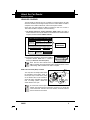
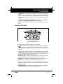
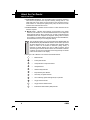
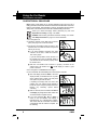
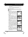
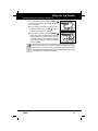
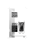
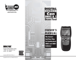
CAR READER
E1
Table of Contents
Title
Page No.
YOU CAN DO IT! . . . . . . . . . . . . . . . . . . . . . . . . . . . . . . . . . . . . . . . . . . . . . 1
SAFETY PRECAUTIONS
Safety First . . . . . . . . . . . . . . . . . . . . . . . . . . . . . . . . . . . . . . . . . . . . . 2
ABOUT THE CAR READER
Vehicles Covered . . . . . . . . . . . . . . . . . . . . . . . . . . . . . . . . . . . . . . . . 3
Controls and Indicators . . . . . . . . . . . . . . . . . . . . . . . . . . . . . . . . . . . . 4
Display Functions . . . . . . . . . . . . . . . . . . . . . . . . . . . . . . . . . . . . . . . . 5
PREPARATION FOR TESTING
Before You Begin . . . . . . . . . . . . . . . . . . . . . . . . . . . . . . . . . . . . . . . . . 7
Vehicle Service Manuals . . . . . . . . . . . . . . . . . . . . . . . . . . . . . . . . . . . 7
USING THE CODE READER
Code Retrieval Procedure . . . . . . . . . . . . . . . . . . . . . . . . . . . . . . . . . . 8
Erasing Diagnostic Trouble Codes (DTCs) . . . . . . . . . . . . . . . . . . . . . . 10
DTC DEFINITIONS
Diagnostic Trouble Code Definitions . . . . . . . . . . . . . . . . . . . . . . . . . . . 12
LIMITED WARRANTY AND SERVICE PROCEDURES
The Manufacturer warrants to the original purchaser that this unit is free of defects in materials and
workmanship under normal use and maintenance for a period of one (1) year from the date of original
purchase. If the unit fails within the one (1) year period, it will be repaired or replaced, at the Manufacturer's
option, at no charge, when returned prepaid to the Technical Service Center with Proof of Purchase. The
sales receipt may be used for this purpose. Installation labor is not covered under this warranty.
All replacement parts, whether new or re-manufactured, assume as their warranty period for only the
remaining time of this warranty. This warranty does not apply to damage caused by improper use, accident,
abuse, improper voltage, service, fire, flood, lightning, or other acts of God, or if the product was altered or
repaired by anyone other than the Manufacturer's Technical Service Center. Consequential and incidental
damages are not recoverable under this warranty. Some states do not allow the exclusion or limitation of
incidental or consequential damages, so the above limitation or exclusion may not apply to you.
This warranty gives you specific legal rights, and you may also have other rights, which vary from state
to state. No portion of this warranty may be copied or duplicated without the expressed written permission
from the Manufacturer.
Obtaining Warranty Service:
Products requiring service should be returned as follows:
1.
Call the Technical Service Center to obtain a Return Reference Number:
USA & Canada = 1-800-544-4124
Other = 714-241-6805
2.
Package the product carefully to prevent shipping damage
3.
Include your name, return address, and a day contact phone
4.
Enclose a copy of the dated sales receipt
5.
Describe the problem
6.
Ship prepaid to: Technical Service Center, 17291 Mt. Herrmann Street, Fountain Valley, CA 92708
U.S.A.
Phone: 1-800-544-4124 or 714-241-6805
Web: www.iEQUUS.com
i
E2
Fax: 714-432-7910
Email: [email protected]
OBD2
E3
■
The Car Reader will automatically link to the
vehicle’s computer.
■
The Car Reader retrieves stored codes and
displays I/M Readiness status.
■
Codes are displayed on the Car Reader’s LCD
display screen; I/M Readiness status is displayed
by LED indicators.
Easy To Define . . . .
■
OBD2
Locate fault code(s) in the Fault Code Definition
list.
4
Turn the ignition key "On.” DO NOT start the
engine.
04
4
■
P
Connect the Car Reader to the vehicle’s test
connector.
45
■
tr
sm p a e ys
t
t
E a ora ive Em T
l
V va l l tiv E is em De
a p e
m s p fi
E lve ora ak e E is io er ni
va C t ) m si n a tio
V
P
is on Co tur n
a p i iv
04
si C n e
E lv or rc e
on o tr B
46 V va e at ui Em
n o
C
t
P
C tr l S elo
a p i iv M is
04
on ol y w
E lv or rc e
a s
47 C va e at ui Em lfu ion
tr S st
C
t
i
ol ys em
P
ir p i v O is n C
04
S tem M
E cu ora rcu e E pe sio cti on
ys
48 C v it t i m n n on t
a
t
ro
te In
P
C
ir p M iv S is
l
04
m co
h s
on
S
E c or a e
ys
49 C va uit at lfu Em or ion
L rr
tr
t
i
ea
t
ol
P
ir p O v n is ed C
em
04
k
on
S
E cu ora pe e E cti sio
D
ys
50 S va it t n m on n
P
tr
et
i
u
t
ol
P
is
o p S v
C
em
rg
04
si
on
S
E len ora ho e E
e
on
ys
51 M va o t rt m
P
tr
C
i
i
u
e
t
d
o
o
v
P
C
em
d iss
rg
a p
n
l
04
on
S
t
E lfu ora Ci e E
i
e
r
on
ys
52 R va n t rc m
P
ol
tr
C
u
te
on
ol
C
a p ct iv ui is
rg
m
on
S
tr
E ng ora ion e E t M sio
45
e
ys
V
ol
tr
m a n
C
3 L vap e/P tiv
en
te
on
ol
is lf C
o
e
m
si un on
t
S
tr
E w I ora rf e E
C
o
ys
V
ol
n ct tr
on
H va np tiv orm m
en
te
is
C io ol
i p
u
tr
m
on n S
t
E gh ora t e E an sio
ol
C
ys
va I t
V
tr
m ce n
on
en
te
ol
p np ive
is
C
t
04
P
EASY TO USE - EASY TO VIEW - EASY TO DEFINE
You Can Do It!
Easy To Use . . . .
Easy To View . . . .
1
Safety Precautions
SAFETY FIRST
SAFETY FIRST!
This manual describes common test procedures used by experienced service
technicians. Many test procedures require precautions to avoid accidents that
can result in personal injury, and/or damage to your vehicle or test equipment.
Always read your vehicle's service manual and follow its safety precautions
before and during any test or service procedure. ALWAYS observe the following
general safety precautions:
When an engine is running, it produces carbon monoxide, a toxic
and poisonous gas. To prevent serious injury or death from carbon
monoxide poisoning, operate the vehicle ONLY in a well-ventilated
area.
To protect your eyes from propelled objects as well as hot or caustic
liquids, always wear approved safety eye protection.
When an engine is running, many parts (such as the coolant fan,
pulleys, fan belt etc.) turn at high speed. To avoid serious injury,
always be aware of moving parts. Keep a safe distance from these
parts as well as other potentially moving objects.
Engine parts become very hot when the engine is running. To
prevent severe burns, avoid contact with hot engine parts.
P RND L
Before starting an engine for testing or trouble-shooting, make sure
the parking brake is engaged. Put the transmission in park (for
automatic transmission) or neutral (for manual transmission). Block
the drive wheels with suitable blocks.
Connecting or disconnecting test equipment when the ignition is ON
can damage test equipment and the vehicle's electronic components. Turn the ignition OFF before connecting the Code Reader
to or disconnecting the Code Reader from the vehicle’s Data Link
Connector (DLC).
To prevent damage to the on-board computer when taking vehicle
electrical measurements, always use a digital multimeter with at
least 10 megOhms of impedance.
The vehicle's battery produces highly flammable hydrogen gas. To
prevent an explosion, keep all sparks, heated items and open flames
away from the battery.
Don't wear loose clothing or jewelry when working on an engine.
Loose clothing can become caught in the fan, pulleys, belts, etc.
Jewelry is highly conductive, and can cause a severe burn if it
makes contact between a power source and ground.
2
E4
OBD2
About the Car Reader
VEHICLES COVERED
VEHICLES COVERED
The Car Reader is designed to work on all OBD 2 compliant vehicles. All 1996
and newer vehicles (cars and light trucks) sold in the United States are OBD 2
compliant. This includes all Domestic, Asian and European vehicles.
Some 1994 and 1995 vehicles are OBD 2 compliant. To find out if a 1994 or
1995 vehicle is OBD 2 compliant, check the following:
1. The Vehicle Emissions Control Information (VECI) Label. This label is
located under the hood or by the radiator of most vehicles. If the vehicle is OBD 2
compliant, the label will state “OBD II Certified.”
VEHICLE EMISSION CONTROL INFORMATION
ENGINE FAMILY
DISPLACEMENT
VEHICLE
MANUFACTURER
EFN2.6YBT2BA
2.6L
OBD II
CERTIFIED
THIS VEHICLE CONFORMS TO U.S. EPA AND STATE
OF CALIFORNIA REGULATIONS APPLICABLE TO
1999 MODEL YEAR NEW TLEV PASSENGER CARS.
REFER TO SERVICE MANUAL FOR ADDITIONAL INFORMATION
TUNE-UP CONDITIONS: NORMAL OPERATING ENGINE TEMPERATURE,
ACCESSORIES OFF, COOLING FAN OFF, TRANSMISSION IN NEUTRAL
EXHAUST EMISSIONS STANDARDS
CERTIFICATION
IN-USE
SPARK PLUG
TYPE NGK BPRE-11
GAP: 1.1MM
OBD II
CERTIFIED
STANDARD CATEGORY
TLEV
TLEV INTERMEDIATE
CATALYST
2. Government Regulations require that all OBD 2
compliant vehicles must have a “common”
sixteen-pin Data Link Connector (DLC).
1 2 3 4 5 6 7 8
9 10111213141516
Some 1994 and 1995 vehicles have 16-pin connectors but are not
OBD 2 compliant. Only those vehicles with a Vehicle Emissions Control
Label stating “OBD II Certified” are OBD 2 compliant.
Data Link Connector (DLC) Location
The 16-pin DLC is usually located under
the instrument panel (dash), within 12
inches (300 mm) of center of the panel,
on the driver’s side of most vehicles. It
should be easily accessible and visible
from a kneeling position outside the
vehicle with the door open.
LEFT CORNER
OF DASH
NEAR
CENTER
OF DASH
BEHIND
ASHTRAY
On some Asian and European vehicles the DLC is located behind the
“ashtray” (the ashtray must be removed to access it) or on the far left
corner of the dash. If the DLC cannot be located, consult the vehicle’s
service manual for the location.
OBD2
E5
3
About the Car Reader
CONTROLS AND INDICATORS
CONTROLS AND INDICATORS
7
5
4
6
1
3
2
8
Figure 1. Controls and Indicators
See Figure 1 for the locations of items 1 through 9, below.
4
E6
1.
ERASE button - Erases Diagnostic Trouble Codes (DTCs) and "Freeze
Frame" data from your vehicle's computer, and resets Monitor status.
2.
SCROLL button - Scrolls the LCD display to view DTCs when more than
one DTC is present.
3.
LINK button - Links the Car Reader with the vehicle's PCM to retrieve
DTCs from the computer's memory, and to view I/M Readiness Monitor
status.
4.
GREEN LED - Indicates that all engine systems are running normally (all
Monitors on the vehicle are active and performing their diagnostic testing, and
no DTCs are present).
5.
YELLOW LED - Indicates there is a possible problem. A “Pending” DTC
is present and/or some of the vehicle's emission monitors have not run their
diagnostic testing.
OBD2
About the Car Reader
DISPLAY FUNCTIONS
6.
RED LED - Indicates there is a problem in one or more of the vehicle's
systems. The red LED is also used to show that DTC(s) are present. DTCs
are shown on the Car Reader’s LCD display. In this case, the Multifunction
Indicator (“Check Engine”) lamp on the vehicle's instrument panel will light
steady on.
7. LCD Display - Displays test results, Car Reader functions and Monitor status
information. See DISPLAY FUNCTIONS, below, for details.
8. CABLE - Connects the Car Reader to the vehicle's Data Link Connector
(DLC).
DISPLAY FUNCTIONS
10
5
4
6
1
2
8
9
7
3
Figure 2. Display Functions
See Figure 2 for the locations of items 1 through 13, below.
1.
Vehicle icon - Indicates whether or not the Car Reader is being properly
powered through the vehicle's Data Link Connector (DLC). A visible icon
indicates that the Car Reader is being powered through the vehicle's DLC
connector.
2.
Link icon - Indicates whether or not the Car Reader is communicating
(linked) with the vehicle's on-board computer. When visible, the Car Reader
is communicating with the computer. If the Link icon is not visible, the Car
Reader is not communicating with the computer.
3. DTC Display Area - Displays the Diagnostic Trouble Code (DTC) number.
Each fault is assigned a code number that is specific to that fault.
4. Pending icon - Indicates the currently displayed DTC is a "Pending" code.
5. CODE icon - Identifies the Code Number Sequence display area.
6. MIL icon - Indicates the status of the Malfunction Indicator Lamp (MIL). The
MIL icon is visible only when a DTC has commanded the MIL on the vehicle's
dashboard to light.
7. FREEZE FRAME icon - Indicates that “Freeze Frame” data has been stored
in the vehicle’s computer for the currently displayed DTC.
OBD2
E7
5
About the Car Reader
DISPLAY FUNCTIONS
8. Code Number Sequence - The Car Reader assigns a sequence number to
each DTC that is present in the computer's memory, starting with "01.” This
helps keep track of the number of DTCs present in the computer's memory.
Code number "01" is always the highest priority code, and the one for which
"Freeze Frame" data has been stored.
9. Code Enumerator - Indicates the total number of codes retrieved from the
vehicle’s computer.
10. Monitor icons - Indicates which Monitors are supported by the vehicle
under test, and whether or not the associated Monitor has run its diagnostic
testing (Monitor status). When a Monitor icon is solid, it indicates that the
associated Monitor has completed its diagnostic testing. When a Monitor
icon is flashing, it indicates that the vehicle supports the associated Monitor,
but the Monitor has not yet run its diagnostic testing.
The I/M Monitor Status icons are associated with INSPECTION and
MAINTENANCE (I/M) READINESS STATUS. Some states require that
all vehicle Monitors have run and completed their diagnostic testing
before a vehicle can be tested for Emissions (Smog Check). A
maximum of eleven Monitors are used on OBD 2 systems. Not all
vehicles support all eleven Monitors. When the Car Reader is linked to
a vehicle, only the icons for Monitors that are supported by the vehicle
under test are visible on the display.
Following is a list of Monitor icons and their associated Monitors.
6
E8
=
Misfire Monitor
=
Fuel System Monitor
=
Comprehensive Component Monitor
=
Catalyst Monitor
=
Heated Catalyst Monitor
=
Evaporative System Monitor
=
Secondary Air System Monitor
=
Air Conditioning System Refrigerant (R-12) Monitor
=
Oxygen Sensor Monitor
=
Oxygen Sensor Heater Monitor
=
Exhaust Gas Recirculation (EGR) Monitor
OBD2
Preparation for Testing
BEFORE YOU BEGIN / VEHICLE SERVICE MANUALS
BEFORE YOU BEGIN
Fix any known mechanical problems before performing any test. See your
vehicle's service manual or a mechanic for more information. Check the
following areas before starting any test:
■
Check the engine oil, power steering fluid, transmission fluid (if
applicable), engine coolant and other fluids for proper levels. Top off low
fluid levels if needed.
■
Make sure the air filter is clean and in good condition. Make sure all air filter
ducts are properly connected. Check the air filter ducts for holes, rips or cracks.
■
Make sure all engine belts are in good condition. Check for cracked, torn,
brittle, loose or missing belts.
■
Make sure mechanical linkages to engine sensors (throttle, gearshift position,
transmission, etc.) are secure and properly connected. See your vehicle's
service manual for locations.
■
Check all rubber hoses (radiator) and steel hoses (vacuum/fuel) for leaks,
cracks, blockage or other damage. Make sure all hoses are routed and
connected properly.
■
Make sure all spark plugs are clean and in good condition. Check for
damaged, loose, disconnected or missing spark plug wires.
■
Make sure the battery terminals are clean and tight. Check for corrosion or
broken connections. Check for proper battery and charging system voltages.
■
Check all electrical wiring and harnesses for proper connection. Make sure
wire insulation is in good condition, and there are no bare wires.
■
Make sure the engine is mechanically sound. If needed, perform a
compression check, engine vacuum check, timing check (if applicable), etc.
VEHICLE SERVICE MANUALS
Always refer to the manufacturer's service manual for your vehicle before
performing any test or repair procedures. Contact your local car dealership, auto
parts store or bookstore for availability of these manuals. The following
companies publish valuable repair manuals:
■
Haynes Publications - 861 Lawrence Drive, Newbury Park, California
91320 Phone: 800-442-9637
■
Mitchell International - 14145 Danielson Street, Poway, California 92064
Phone: 888-724-6742
■
Motor Publications - 5600 Crooks Road, Suite 200 , Troy, Michigan 48098
Phone: 800-426-6867
FACTORY SOURCES
Ford, GM, Chrysler, Honda, Isuzu, Hyundai and Subaru Service Manuals
■
OBD2
E9
Helm Inc.- -14310 Hamilton Avenue, Highland Park, Michigan 48203
Phone: 800-782-4356
7
Using the Car Reader
CODE RETRIEVAL PROCEDURE
CODE RETRIEVAL PROCEDURE
Never replace a part based only on the DTC definition. Each DTC has a set of
testing procedures, instructions and flow charts that must be followed to confirm the
location of the problem. This information is found in the vehicle's service manual.
Always refer to the vehicle's service manual for detailed testing instructions.
Check your vehicle thoroughly before performing any test. See
Preparation for Testing on page 7 for details.
ALWAYS observe safety precautions whenever working on a vehicle.
See Safety Precautions on page 2 for more information.
1. Turn the ignition off.
2. Locate the vehicle's 16-pin Data Link Connector
(DLC). See page 3 for connector location.
3. Connect the Car Reader’s cable connector to the
vehicle's DLC. The cable connector is keyed and
will only fit one way.
■
If you have problems connecting the cable
connector to the DLC, rotate the connector
180° and try again.
If you still have problems, check the DLC on
the vehicle and on the Car Reader. Refer to
your vehicle's service manual to properly check
the vehicle's DLC.
■
After the Car Reader’s test connector is properly connected to the
vehicle's DLC, the Vehicle icon
should display to confirm a good
power connection.
4. Turn the ignition on. DO NOT start the engine.
5. The Car Reader will automatically link to the vehicle’s computer.
■
The LCD display will show "rEAd.” If the LCD
display is blank, it indicates there is no power
at the vehicle's DLC. Check your fuse panel
and replace any burned-out fuses.
If replacing the fuse(s) does not correct the
problem, see your vehicle's repair manual to
locate the proper computer (PCM) fuse/circuit.
Perform any necessary repairs before
continuing.
8
E10
■
After 4-5 seconds, the Car Reader will retrieve
and display any Diagnostic Trouble Codes that
are in the vehicle's computer memory.
■
If an error message (Err, Err1 or Err2) is
shown on the Car Reader’s LCD display, it
indicates there is a communication problem.
This means that the Car Reader is unable to
communicate with the vehicle's computer. Do
the following:
OBD2
Using the Car Reader
CODE RETRIEVAL PROCEDURE
- Turn the ignition key off, wait 5 seconds and turn the key back on to
reset the computer.
- Make sure your vehicle is OBD 2 compliant. See VEHICLES COVERED
on page 2 for vehicle compliance verification information.
6. Read and interpret the Diagnostic Trouble Codes using the LCD display and
the green, yellow and red LEDs.
The green, yellow and red LEDs are used (with the LCD display) as
visual aids to make it easier for the user to determine engine system
conditions.
■
Green LED
- Indicates that all engine
systems are "OK" and running normally. All
monitors on the vehicle are active and are
performing their diagnostic testing, and no
trouble codes are present. A zero will show on
the Car Reader’s LCD display for further
confirmation.
■
Yellow LED
conditions:
- Indicates one of the following
PENDING CODE PRESENT - If the yellow
LED is lit, it may indicate the existence of a
pending code. Check the Car Reader’s LCD
display for confirmation. A pending code is
confirmed by the presence of a numeric code
and the word PENDING on the Car Reader’s
LCD display. If no pending code is shown, the
yellow LED indicates Monitor Status (see the
following).
MONITOR STATUS - If the Car Reader’s LCD
display shows a zero (indicating there are no
DTCs present in the vehicle's computer), but
the yellow LED is lit, it indicates a "Monitor Has
Not Run" status. This means that some of the
Monitors on the vehicle have not yet finished
their diagnostic self-testing. This condition is
confirmed by one or more blinking Monitor
icons on the LCD display. A blinking Monitor
icon means the Monitor has not yet run and
finished its diagnostic self-testing. All Monitor
icons that are solid have completed their
diagnostic self-testing.
■
OBD2
E11
Red LED
- Indicates there is a problem with
one or more of the vehicle's systems. The red
LED is also used to show that DTC(s) are
present (displayed on the Car Reader’s LCD
display). In this case, the Multifunction Indicator
(Check Engine) lamp on the vehicle's instrument
panel will light steady on.
9
Using the Car Reader
ERASING DIAGNOSTIC TROUBLE CODES (DTCs)
The Car Reader will automatically re-link to the vehicle's
computer every 15 seconds to refresh the data being retrieved.
When data is being refreshed, a single beep will sound, and
"rEAd" will be shown on the LCD display for 5-6 seconds. The
Car Reader will then beep twice and return to displaying codes.
This action repeats as long as the Car Reader is in communication with the vehicle's computer.
The Car Reader will display a code only if codes are present in
the vehicle's computer memory. If no codes are present, a "0" will
be displayed.
7. If more than one code is present, press and release the SCROLL
as necessary, to display additional codes.
■
button,
Whenever the SCROLL function is used to view additional codes, the Car
Reader’s communication link with the vehicle's computer disconnects. To
re-establish communication, press the LINK
button again.
Refer to page 14 for Diagnostic Trouble Code definitions. Match the retrieved
DTC(s) with those listed. Read the associated definition(s), and see the vehicle's
service manual for further evaluation.
ERASING DIAGNOSTIC TROUBLE CODES (DTCs)
When the Car Reader’s ERASE function is used to erase the DTCs
from the vehicle's on-board computer, "Freeze Frame" data and
manufacturer-specific enhanced data are also erased.
If you plan to take the vehicle to a Service Center for repair, DO NOT erase the
codes from the vehicle's computer. If the codes are erased, valuable information
that might help the technician troubleshoot the problem will also be erased.
Erase DTCs from the computer's memory as follows:
When DTCs are erased from the vehicle's computer memory, the I/M
Readiness Monitor Status program resets status of all the Monitors to
a not run "flashing" condition. To set all of the Monitors to a DONE
status, an OBD 2 Drive Cycle must be performed. Refer to your
vehicle's service manual for information on how to perform an OBD 2
Drive Cycle for the vehicle under test.
1. If not connected already, connect the Car Reader
to the vehicle's DLC. (If the Car Reader is already
connected and linked to the vehicle's computer,
proceed directly to step 4. If not, continue to step
2.)
2. Turn the ignition on. DO NOT start the engine. The
Car Reader will automatically link to the vehicle’s
computer.
10
E12
OBD2
Using the Car Reader
ERASING DIAGNOSTIC TROUBLE CODES (DTCs)
3. Press and release the Car Reader’s ERASE
button. The LCD display will indicate "SurE" for
your confirmation.
■ If you change your mind and do not wish to
erase the codes, press the LINK
button to
return to the code retrieval function.
■
If you wish to continue, press the ERASE
button again. When all retrievable information,
including DTCs, has been cleared from the
computer’s memory, the Car Reader will re-link
to the vehicle’s computer, and the LCD display
will show "rEAd.”
Erasing DTCs does not fix the problem(s) that caused the code(s) to
be set. If proper repairs to correct the problem that caused the code(s)
to be set are not made, the code(s) will appear again (and the check
engine light will illuminate) as soon as the vehicle is driven long enough
for its Monitors to complete their testing.
OBD2
E13
11
DTC Definitions
DIAGNOSTIC TROUBLE CODE DEFINITIONS
DIAGNOSTIC TROUBLE CODE DEFINITIONS
Diagnostic Trouble Codes (DTCs) are meant to guide you to the proper service
procedure in the vehicle's service manual. DO NOT replace parts based only on
DTCs without first consulting the vehicle's service manual for proper testing
procedures for that particular system, circuit or component.
DTCs are alphanumeric codes that are used to identify a problem that is present
in any of the systems that are monitored by the on-board computer (PCM). Each
trouble code has an assigned message that identifies the circuit, component or
system area where the problem was found.
OBD 2 diagnostic trouble codes are made up of five characters:
■
The 1st character is a letter. It identifies the "main system" where the fault
occurred (Body, Chassis, Powertrain, or Network).
■
The 2nd character is a numeric digit. It identifies the "type" of code (Generic
or Manufacturer-Specific).
Generic DTCs are codes that are used by all vehicle manufacturers.
The standards for generic DTCs, as well as their definitions, are set by
the Society of Automotive Engineers (SAE).
Manufacturer-Specific DTCs are codes that are controlled by the
vehicle manufacturer. The Federal Government does not require
manufacturer-specific codes in order to comply with the new OBD 2
emissions standards. However, manufacturers are free to expand
beyond the required codes to make their systems easier to diagnose.
■
The 3rd character is a numeric digit. It identifies the specific system or subsystem where the problem is located.
■
The 4th and 5th characters are numeric digits. They identify the section of
the system that is malfunctioning.
This section provides the most complete list of “Generic” DTC definitions
available at the time of publication. OBD 2 is an evolving system; new codes and
definitions are added as the system grows. ALWAYS check your vehicle's
service manual for code definitions that are not listed here, or for “ManufacturerSpecific” DTC definitions. For more information, visit our web site at
www.CodeReader.com.
12
E14
OBD2
DTC Definitions
DIAGNOSTIC TROUBLE CODE DEFINITIONS
OBD 2 DTC EXAMPLE
P0201 - Injector Circuit Malfunction, Cylinder 1
B
C
P
U
-
Body
Chassis
Powertrain
Network
0
1
2
3
-
Generic
Manufacturer Specific
Generic
Includes both Generic and Manufacturer
Specific Codes
P0201
Identifies the system where the
problem is located:
1 - Fuel and Air Metering
2 - Fuel and Air Metering (injector circuit
malfunction only)
3 - Ignition System or Misfire
4 - Auxiliary Emission Control System
5 - Vehicle Speed Control and Idle Control
System
6 - Computer Output Circuits
7 - Transmission
8 - Transmission
Identifies what section of the system
is malfunctioning
OBD2
E15
13
DTC Definitions
P0010 - P0075
Code
"A" Camshaft Position - Actuator Circuit (Bank 1)
P0011
"A" Camshaft Position - Timing Over-Advanced or System Performance (Bank 1)
P0012
"A" Camshaft Position - Timing Over-Retarded (Bank 1)
P0013
"B" Camshaft Position - Actuator Circuit (Bank 1)
P0014
"B" Camshaft Position - Timing Over-Advanced or System Performance (Bank 1)
P0015
"B" Camshaft Position - Timing Over-Retarded (Bank 1)
P0020
"A" Camshaft Position - Actuator Circuit (Bank 2)
P0021
"A" Camshaft Position - Timing Over-Advanced or System Performance (Bank 2)
P0022
"A" Camshaft Position - Timing Over-Retarded (Bank 2)
P0023
"B" Camshaft Position - Actuator Circuit (Bank 2)
P0024
"B" Camshaft Position - Timing Over-Advanced or System Performance (Bank 2)
P0025
"B" Camshaft Position - Timing Over-Retarded (Bank 2)
P0030
HO2S Heater Control Circuit (Bank 1 Sensor 1)
P0031
HO2S Heater Control Circuit Low (Bank 1 Sensor 1)
P0032
HO2S Heater Control Circuit High (Bank 1 Sensor 1)
P0033
Turbo Charger Bypass Valve Control Circuit
P0034
Turbo Charger Bypass Valve Control Circuit Low
P0035
Turbo Charger Bypass Valve Control Circuit High
P0036
HO2S Heater Control Circuit (Bank 1 Sensor 2)
P0037
HO2S Heater Control Circuit Low (Bank 1 Sensor 2)
P0038
HO2S Heater Control Circuit High (Bank 1 Sensor 2)
P0042
HO2S Heater Control Circuit (Bank 1 Sensor 3)
P0043
HO2S Heater Control Circuit Low (Bank 1 Sensor 3)
P0044
HO2S Heater Control Circuit High (Bank 1 Sensor 3)
P0050
HO2S Heater Control Circuit (Bank 2 Sensor 1)
P0051
HO2S Heater Control Circuit Low (Bank 2 Sensor 1)
P0052
HO2S Heater Control Circuit High (Bank 2 Sensor 1)
P0056
HO2S Heater Control Circuit (Bank 2 Sensor 2)
P0057
HO2S Heater Control Circuit Low (Bank 2 Sensor 2)
P0058
HO2S Heater Control Circuit High (Bank 2 Sensor 2)
P0062
HO2S Heater Control Circuit (Bank 2 Sensor 3)
P0063
HO2S Heater Control Circuit Low (Bank 2 Sensor 3)
P0064
HO2S Heater Control Circuit High (Bank 2 Sensor 3)
P0065
Air Assisted Injector Control Range/Performance
P0066
Air Assisted Injector Control Circuit or Circuit Low
P0067
Air Assisted Injector Control Circuit High
P0070
Ambient Air Temperature Sensor Circuit
P0071
Ambient Air Temperature Sensor Range/Performance
P0072
Ambient Air Temperature Sensor Circuit Low Input
P0073
Ambient Air Temperature Sensor Circuit High Input
P0074
Ambient Air Temperature Sensor Circuit Intermittent
P0075
Intake Valve Control Solenoid Circuit (Bank 1)
14
E16
Definition
P0010
OBD2
DTC Definitions
P0076 - P0128
Code
Definition
P0076
Intake Valve Control Solenoid Circuit Low (Bank 1)
P0077
Intake Valve Control Solenoid Circuit High (Bank 1)
P0078
Exhaust Valve Control Solenoid Circuit (Bank 1)
P0079
Exhaust Valve Control Solenoid Circuit Low (Bank 1)
P0080
Exhaust Valve Control Solenoid Circuit High (Bank 1)
P0081
Intake Valve Control Solenoid Circuit (Bank 2)
P0082
Intake Valve Control Solenoid Circuit Low (Bank 2)
P0083
Intake Valve Control Solenoid Circuit High (Bank 2)
P0084
Exhaust Valve Control Solenoid Circuit (Bank 2)
P0085
Exhaust Valve Control Solenoid Circuit Low (Bank 2)
P0086
Exhaust Valve Control Solenoid Circuit High (Bank 2)
P0100
Mass or Volume Air Flow Circuit Malfunction
P0101
Mass or Volume Circuit Range Performance Problem
P0102
Mass or Volume Circuit Low Input
P0103
Mass or Volume Circuit High Input
P0104
Mass or Volume Circuit Intermittent
P0105
Manifold Absolute Pressure/Barometric Pressure Circuit Malfunction
P0106
Manifold Absolute Pressure/Barometric Pressure CircuitRange/Performance
Problem
P0107
Manifold Absolute Pressure/Barometric Pressure Circuit Low Input
P0108
Manifold Absolute Pressure/Barometric Pressure Circuit High Input
P0109
Manifold Absolute Pressure/Barometric Pressure Circuit Intermittent
P0110
Intake Air Temperature Circuit Malfunction
P0111
Intake Air Temperature Circuit Range/Performance Problem
P0112
Intake Air Temperature Circuit Low Input
P0113
Intake Air Temperature Circuit High Input
P0114
Intake Air Temperature Circuit Intermittent
P0115
Engine Coolant Temperature Circuit Malfunction
P0116
Engine Coolant Temperature Circuit Range/Performance Problem
P0117
Engine Coolant Temperature Circuit Low Input
P0118
Engine Coolant Temperature Circuit High Input
P0119
Engine Coolant Temperature Circuit Intermittent
P0120
Throttle/Pedal Position Sensor/Switch A Circuit Malfunction
P0121
Throttle/Pedal Position Sensor/Switch A Circuit Range/Performance Problem
P0122
Throttle/Pedal Position Sensor/Switch A Circuit Low Input
P0123
Throttle/Pedal Position Sensor/Switch A Circuit High Input
P0124
Throttle/Pedal Position Sensor/Switch A Circuit Intermittent
P0125
Insufficient Coolant Temperature for Closed Loop Fuel
P0126
Insufficient Coolant Temperature for Stable Operation
P0127
Intake Air Temperature Too High
P0128
Coolant Thermostat (Coolant Temperature Below Thermostat Regulating
Temperature)
Control
OBD2
E17
15
DTC Definitions
P0130 - P0171
Code
O2 Sensor Circuit Malfunction (Bank 1 Sensor 1)
P0131
O2 Sensor Circuit Low Voltage (Bank 1 Sensor 1)
P0132
O2 Sensor Circuit High Voltage (Bank 1 Sensor 1)
P0133
O2 Sensor Circuit Slow Response (Bank 1 Sensor 1)
P0134
O2 Sensor Circuit No Activity Detected (Bank 1 Sensor 1)
P0135
O2 Sensor Heater Circuit Malfunction (Bank 1 Sensor 1)
P0136
O2 Sensor Circuit Malfunction (Bank 1 Sensor 2)
P0137
O2 Sensor Circuit Low Voltage (Bank 1 Sensor 2)
P0138
O2 Sensor Circuit High Voltage (Bank 1 Sensor 2)
P0139
O2 Sensor Circuit Slow Response (Bank 1 Sensor 2)
P0140
O2 Sensor Circuit No Activity Detected (Bank 1 Sensor 2)
P0141
O2 Sensor Heater Circuit Malfunction (Bank 1 Sensor 2)
P0142
O2 Sensor Circuit Malfunction (Bank 1 Sensor 3)
P0143
O2 Sensor Circuit Low Voltage (Bank 1 Sensor 3)
P0144
O2 Sensor Circuit High Voltage (Bank 1 Sensor 3)
P0145
O2 Sensor Circuit Slow Response (Bank 1 Sensor 3)
P0146
O2 Sensor Circuit No Activity Detected (Bank 1 Sensor 3)
P0147
O2 Sensor Heater Circuit Malfunction (Bank 1 Sensor 3)
P0148
Fuel Delivery Error
P0149
Fuel Timing Error
P0150
O2 Sensor Circuit Malfunction (Bank 2 Sensor 1)
P0151
O2 Sensor Circuit Low Voltage (Bank 2 Sensor 1)
P0152
O2 Sensor Circuit High Voltage (Bank 2 Sensor 1)
P0153
O2 Sensor Circuit Slow Response (Bank 2 Sensor 1)
P0154
O2 Sensor Circuit No Activity Detected (Bank 2 Sensor 1)
P0155
O2 Sensor Heater Circuit Malfunction (Bank 2 Sensor 1)
P0156
O2 Sensor Circuit Malfunction (Bank 2 Sensor 2)
P0157
O2 Sensor Circuit Low Voltage (Bank 2 Sensor 2)
P0158
O2 Sensor Circuit High Voltage (Bank 2 Sensor 2)
P0159
O2 Sensor Circuit Slow Response (Bank 2 Sensor 2)
P0160
O2 Sensor Circuit No Activity Detected (Bank 2 Sensor 2)
P0161
O2 Sensor Heater Circuit Malfunction (Bank 2 Sensor 2)
P0162
O2 Sensor Circuit Malfunction (Bank 2 Sensor 3)
P0163
O2 Sensor Circuit Low Voltage (Bank 2 Sensor 3)
P0164
O2 Sensor Circuit High Voltage (Bank 2 Sensor 3)
P0165
O2 Sensor Circuit Slow Response (Bank 2 Sensor 3)
P0166
O2 Sensor Circuit No Activity Detected (Bank 2 Sensor 3)
P0167
O2 Sensor Heater Circuit Malfunction (Bank 2 Sensor 3)
P0168
Fuel Temperature Too High
P0169
Incorrect Fuel Composition
P0170
Fuel Trim Malfunction (Bank 1)
P0171
System too Lean (Bank 1)
16
E18
Definition
P0130
OBD2
DTC Definitions
P0172 - P0213
Code
System too Rich (Bank 1)
P0173
Fuel Trim Malfunction (Bank 2)
P0174
System too Lean (Bank 2)
P0175
System too Rich (Bank 2)
P0176
Fuel Composition Sensor Circuit Malfunction
P0177
Fuel Composition Sensor Circuit Range/Performance
P0178
Fuel Composition Sensor Circuit Low Input
P0179
Fuel Composition Sensor Circuit High Input
P0180
Fuel Temperature Sensor A Circuit Malfunction
P0181
Fuel Temperature Sensor A Circuit Range/Performance
P0182
Fuel Temperature Sensor A Circuit Low Input
P0183
Fuel Temperature Sensor A Circuit High Input
P0184
Fuel Temperature Sensor A Circuit Intermittent
P0185
Fuel Temperature Sensor B Circuit Malfunction
P0186
Fuel Temperature Sensor B Circuit Range/Performance
P0187
Fuel Temperature Sensor B Circuit Low Input
P0188
Fuel Temperature Sensor B Circuit High Input
P0189
Fuel Temperature Sensor B Circuit Intermittent
P0190
Fuel Rail Pressure Sensor Circuit Malfunction
P0191
Fuel Rail Pressure Sensor Circuit Range/Performance
P0192
Fuel Rail Pressure Sensor Circuit Low Input
P0193
Fuel Rail Pressure Sensor Circuit High Input
P0194
Fuel Rail Pressure Sensor Circuit Intermittent
P0195
Engine Oil Temperature Sensor Malfunction
P0196
Engine Oil Temperature Sensor Range/Performance
P0197
Engine Oil Temperature Sensor Low
P0198
Engine Oil Temperature Sensor High
P0199
Engine Oil Temperature Sensor Intermittent
P0200
Injector Circuit Malfunction
P0201
Injector Circuit Malfunction - Cylinder 1
P0202
Injector Circuit Malfunction - Cylinder 2
P0203
Injector Circuit Malfunction - Cylinder 3
P0204
Injector Circuit Malfunction - Cylinder 4
P0205
Injector Circuit Malfunction - Cylinder 5
P0206
Injector Circuit Malfunction - Cylinder 6
P0207
Injector Circuit Malfunction - Cylinder 7
P0208
Injector Circuit Malfunction - Cylinder 8
P0209
Injector Circuit Malfunction - Cylinder 9
P0210
Injector Circuit Malfunction - Cylinder 10
P0211
Injector Circuit Malfunction - Cylinder 11
P0212
Injector Circuit Malfunction - Cylinder 12
P0213
Cold Start Injector 1 Malfunction
OBD2
E19
Definition
P0172
17
DTC Definitions
P0214 - P0255
Code
Cold Start Injector 2 Malfunction
P0215
Engine Shutoff Solenoid Malfunction
P0216
Injection Timing Control Circuit Malfunction
P0217
Engine Overtemp Condition
P0218
Transmission Over Temperature Condition
P0219
Engine Overspeed Condition
P0220
Throttle/Pedal Position Sensor/Switch B Circuit Malfunction
P0221
Throttle/Pedal Position Sensor/Switch B Circuit Range/Performance Problem
P0222
Throttle/Pedal Position Sensor/Switch B Circuit Low Input
P0223
Throttle/Pedal Position Sensor/Switch B Circuit High Input
P0224
Throttle/Pedal Position Sensor/Switch B Circuit Intermittent
P0225
Throttle/Pedal Position Sensor/Switch C Circuit Malfunction
P0226
Throttle/Pedal Position Sensor/Switch C Circuit Range/Performance Problem
P0227
Throttle/Pedal Position Sensor/Switch C Circuit Low Input
P0228
Throttle/Pedal Position Sensor/Switch C Circuit High Input
P0229
Throttle/Pedal Position Sensor/Switch C Circuit Intermittent
P0230
Fuel Pump Primary Circuit Malfunction
P0231
Fuel Pump Secondary Circuit Low
P0232
Fuel Pump Secondary Circuit High
P0233
Fuel Pump Secondary Circuit Intermittent
P0234
Engine Overboost Condition
P0235
Turbocharger Boost Sensor A Circuit Malfunction
P0236
Turbocharger Boost Sensor A Circuit Range/Performance
P0237
Turbocharger Boost Sensor A Circuit Low
P0238
Turbocharger Boost Sensor A Circuit High
P0239
Turbocharger Boost Sensor B Circuit Malfunction
P0240
Turbocharger Boost Sensor B Circuit Range/Performance
P0241
Turbocharger Boost Sensor B Circuit Low
P0242
Turbocharger Boost Sensor B Circuit High
P0243
Turbocharger Wastegate Solenoid A Malfunction
P0244
Turbocharger Wastegate Solenoid A Range/Performance
P0245
Turbocharger Wastegate Solenoid A Low
P0246
Turbocharger Wastegate Solenoid A High
P0247
Turbocharger Wastegate Solenoid B Malfunction
P0248
Turbocharger Wastegate Solenoid B Range/Performance
P0249
Turbocharger Wastegate Solenoid B Low
P0250
Turbocharger Wastegate Solenoid B High
P0251
Injection Pump A Rotor/Cam Malfunction
P0252
Injection Pump A Rotor/Cam Range/Performance
P0253
Injection Pump A Rotor/Cam Low
P0254
Injection Pump A Rotor/Cam High
P0255
Injection Pump A Rotor/Cam Intermitted
18
E20
Definition
P0214
OBD2
DTC Definitions
P0256 - P0298
Code
Injection Pump B Rotor/Cam Malfunction
P0257
Injection Pump B Rotor/Cam Range/Performance
P0258
Injection Pump B Rotor/Cam Low
P0259
Injection Pump B Rotor/Cam High
P0260
Injection Pump B Rotor/Cam Intermitted
P0261
Cylinder 1 Injector Circuit Low
P0262
Cylinder 1 Injector Circuit High
P0263
Cylinder 1 Contribution/Balance Fault
P0264
Cylinder 2 Injector Circuit Low
P0265
Cylinder 2 Injector Circuit High
P0266
Cylinder 2 Contribution/Balance Fault
P0267
Cylinder 3 Injector Circuit Low
P0268
Cylinder 3 Injector Circuit High
P0269
Cylinder 3 Contribution/Balance Fault
P0270
Cylinder 4 Injector Circuit Low
P0271
Cylinder 4 Injector Circuit High
P0272
Cylinder 4 Contribution/Balance Fault
P0273
Cylinder 5 Injector Circuit Low
P0274
Cylinder 5 Injector Circuit High
P0275
Cylinder 5 Contribution/Balance Fault
P0276
Cylinder 6 Injector Circuit Low
P0277
Cylinder 6 Injector Circuit High
P0278
Cylinder 6 Contribution/Balance Fault
P0279
Cylinder 7 Injector Circuit Low
P0280
Cylinder 7 Injector Circuit High
P0281
Cylinder 7 Contribution/Balance Fault
P0282
Cylinder 8 Injector Circuit Low
P0283
Cylinder 8 Injector Circuit High
P0284
Cylinder 8 Contribution/Balance Fault
P0285
Cylinder 9 Injector Circuit Low
P0286
Cylinder 9 Injector Circuit High
P0287
Cylinder 9 Contribution/Balance Fault
P0288
Cylinder 10 Injector Circuit Low
P0289
Cylinder 10 Injector Circuit High
P0290
Cylinder 10 Contribution/Balance Fault
P0291
Cylinder 11 Injector Circuit Low
P0292
Cylinder 11 Injector Circuit High
P0293
Cylinder 11 Contribution/Balance Fault
P0294
Cylinder 12 Injector Circuit Low
P0295
Cylinder 12 Injector Circuit High
P0296
Cylinder 12 Contribution/Balance Fault
P0298
Engine Oil Over Temperature
OBD2
E21
Definition
P0256
19
DTC Definitions
P0300 - P0346
Code
Random/Multiple Cylinder Misfire Detected
P0301
Cylinder 1 Misfire Detected
P0302
Cylinder 2 Misfire Detected
P0303
Cylinder 3 Misfire Detected
P0304
Cylinder 4 Misfire Detected
P0305
Cylinder 5 Misfire Detected
P0306
Cylinder 6 Misfire Detected
P0307
Cylinder 7 Misfire Detected
P0308
Cylinder 8 Misfire Detected
P0309
Cylinder 9 Misfire Detected
P0310
Cylinder 10 Misfire Detected
P0311
Cylinder 11 Misfire Detected
P0312
Cylinder 12 Misfire Detected
P0313
Misfire Detected with Low Fuel
P0314
Single Cylinder Misfire (Cylinder not specified)
P0320
Ignition/Distributor Engine Speed Input Circuit Malfunction
P0321
Ignition/Distributor Engine Speed Input Circuit Range/Performance
P0322
Ignition/Distributor Engine Speed Input Circuit No Signal
P0323
Ignition/Distributor Engine Speed Input Circuit Intermittent
P0324
Knock Control System Error
P0325
Knock Sensor 1 Circuit Malfunction (Bank 1 or Single Sensor)
P0326
Knock Sensor 1 Circuit Range/Performance (Bank 1 or Single Sensor)
P0327
Knock Sensor 1 Circuit Low Input (Bank 1 or Single Sensor)
P0328
Knock Sensor 1 Circuit High Input (Bank 1 or Single Sensor)
P0329
Knock Sensor 1 Circuit Intermittent (Bank 1 or Single Sensor)
P0330
Knock Sensor 2 Circuit Malfunction (Bank 2)
P0331
Knock Sensor 2 Circuit Range/Performance (Bank 2)
P0332
Knock Sensor 2 Circuit Low Input (Bank 2)
P0333
Knock Sensor 2 Circuit High Input (Bank 2)
P0334
Knock Sensor 2 Circuit Intermittent (Bank 2)
P0335
Crankshaft Position Sensor A Circuit Malfunction
P0336
Crankshaft Position Sensor A Circuit Range/Performance
P0337
Crankshaft Position Sensor A Circuit Low Input
P0338
Crankshaft Position Sensor A Circuit High Input
P0339
Crankshaft Position Sensor A Circuit Intermittent
P0340
Camshaft Position Sensor Circuit Malfunction
P0341
Camshaft Position Sensor Circuit Range/Performance
P0342
Camshaft Position Sensor Circuit Low Input
P0343
Camshaft Position Sensor Circuit High Input
P0344
Camshaft Position Sensor Circuit Intermittent
P0345
Camshaft Position Sensor "A" Circuit (Bank 2)
P0346
Camshaft Position Sensor "A" Circuit Range/Performance (Bank 2)
20
E22
Definition
P0300
OBD2
DTC Definitions
P0347 - P0392
Code
Camshaft Position Sensor "A" Circuit Low Input (Bank 2)
P0348
Camshaft Position Sensor "A" Circuit High Input (Bank 2)
P0349
Camshaft Position Sensor "A" Circuit Intermittent (Bank 2)
P0350
Ignition Coil Primary/Secondary Circuit Malfunction
P0351
Ignition Coil A Primary/Secondary Circuit Malfunction
P0352
Ignition Coil B Primary/Secondary Circuit Malfunction
P0353
Ignition Coil C Primary/Secondary Circuit Malfunction
P0354
Ignition Coil D Primary/Secondary Circuit Malfunction
P0355
Ignition Coil E Primary/Secondary Circuit Malfunction
P0356
Ignition Coil F Primary/Secondary Circuit Malfunction
P0357
Ignition Coil G Primary/Secondary Circuit Malfunction
P0358
Ignition Coil H Primary/Secondary Circuit Malfunction
P0359
Ignition Coil I Primary/Secondary Circuit Malfunction
P0360
Ignition Coil J Primary/Secondary Circuit Malfunction
P0361
Ignition Coil K Primary/Secondary Circuit Malfunction
P0362
Ignition Coil L Primary/Secondary Circuit Malfunction
P0365
Camshaft Position Sensor "B" Circuit (Bank 1)
P0366
Camshaft Position Sensor "B" Circuit Range/Performance (Bank 1)
P0367
Camshaft Position Sensor "B" Circuit Low Input (Bank 1)
P0368
Camshaft Position Sensor "B" Circuit High Input (Bank 1)
P0369
Camshaft Position Sensor "B" Circuit Intermittent (Bank 1)
P0370
Timing Reference High Resolution Signal A Malfunction
P0371
Timing Reference High Resolution Signal A Too Many Pulses
P0372
Timing Reference High Resolution Signal A Too Few Pulses
P0373
Timing Reference High Resolution Signal A Intermittent/Erratic Pulses
P0374
Timing Reference High Resolution Signal A No Pulses
P0375
Timing Reference High Resolution Signal B Malfunction
P0376
Timing Reference High Resolution Signal B Too Many Pulses
P0377
Timing Reference High Resolution Signal B Too Few Pulses
P0378
Timing Reference High Resolution Signal B Intermittent/Erratic Pulses
P0379
Timing Reference High Resolution Signal B No Pulses
P0380
Glow Plug/Heater Circuit Malfunction
P0381
Glow Plug/Heater Indicator Circuit Malfunction
P0382
Glow Plug/Heater Circuit "B" Malfunction
P0385
Crankshaft Position Sensor B Circuit Malfunction
P0386
Crankshaft Position Sensor B Circuit Range/Performance
P0387
Crankshaft Position Sensor B Circuit Low Input
P0388
Crankshaft Position Sensor B Circuit High Input
P0389
Crankshaft Position Sensor B Circuit Intermittent
P0390
Camshaft Position Sensor "B" Circuit (Bank 2)
P0391
Camshaft Position Sensor "B" Circuit Range/Performance (Bank 2)
P0392
Camshaft Position Sensor "B" Circuit Low Input (Bank 2)
OBD2
E23
Definition
P0347
21
DTC Definitions
P0393 - P0439
Code
Camshaft Position Sensor "B" Circuit High Input (Bank 2)
P0394
Camshaft Position Sensor "B" Circuit Intermittent (Bank 2)
P0400
Exhaust Gas Recirculation Flow Malfunction
P0401
Exhaust Gas Recirculation Flow Insufficient Detected
P0402
Exhaust Gas Recirculation Flow Excessive Detected
P0403
Exhaust Gas Recirculation Circuit Malfunction
P0404
Exhaust Gas Recirculation Circuit Range/Performance
P0405
Exhaust Gas Recirculation Sensor A Circuit Low
P0406
Exhaust Gas Recirculation Sensor A Circuit High
P0407
Exhaust Gas Recirculation Sensor B Circuit Low
P0408
Exhaust Gas Recirculation Sensor B Circuit High
P0409
Exhaust Gas Recirculation Sensor "A" Circuit
P0410
Secondary Air Injection System Malfunction
P0411
Secondary Air Injection System Incorrect Flow Detected
P0412
Secondary Air Injection System Switching Valve A Circuit Malfunction
P0413
Secondary Air Injection System Switching Valve A Circuit Open
P0414
Secondary Air Injection System Switching Valve A Circuit Shorted
P0415
Secondary Air Injection System Switching Valve B Circuit Malfunction
P0416
Secondary Air Injection System Switching Valve B Circuit Open
P0417
Secondary Air Injection System Switching Valve B Circuit Shorted
P0418
Secondary Air Injection System Relay "A" Circuit Malfunction
P0419
Secondary Air Injection System Relay "B" Circuit Malfunction
P0420
Catalyst System Efficiency Below Threshold (Bank 1)
P0421
Warm Up Catalyst Efficiency Below Threshold (Bank 1)
P0422
Main Catalyst Efficiency Below Threshold (Bank 1)
P0423
Heated Catalyst Efficiency Below Threshold (Bank 1)
P0424
Heated Catalyst Temperature Below Threshold (Bank 1)
P0425
Catalyst Temperature Sensor (Bank 1)
P0426
Catalyst Temperature Sensor Range/Performance (Bank 1)
P0427
Catalyst Temperature Sensor Low Input (Bank 1)
P0428
Catalyst Temperature Sensor High Input (Bank 1)
P0429
Catalyst Heater Control Circuit (Bank 1)
P0430
Catalyst System Efficiency Below Threshold (Bank 2)
P0431
Warm Up Catalyst Efficiency Below Threshold (Bank 2)
P0432
Main Catalyst Efficiency Below Threshold (Bank 2)
P0433
Heated Catalyst Efficiency Below Threshold (Bank 2)
P0434
Heated Catalyst Temperature Below Threshold (Bank 2)
P0435
Catalyst Temperature Sensor (Bank 2)
P0436
Catalyst Temperature Sensor Range/Performance (Bank 2)
P0437
Catalyst Temperature Sensor Low Input (Bank 2)
P0438
Catalyst Temperature Sensor High Input (Bank 2)
P0439
Catalyst Heater Control Circuit (Bank 2)
22
E24
Definition
P0393
OBD2
DTC Definitions
P0440 - P0483
Code
Evaporative Emission Control System Malfunction
P0441
Evaporative Emission Control System Incorrect Purge Flow
P0442
Evaporative Emission Control System Leak Detected (small leak)
P0443
Evaporative Emission Control System Purge Control Valve Circuit Malfunction
P0444
Evaporative Emission Control System Purge Control Valve Circuit Open
P0445
Evaporative Emission Control System Purge Control Valve Circuit Shorted
P0446
Evaporative Emission Control System Vent Control Circuit Malfunction
P0447
Evaporative Emission Control System Vent Control Open
P0448
Evaporative Emission Control System Vent Control Circuit Shorted
P0449
Evaporative Emission Control System Vent Valve/Solenoid Circuit Malfunction
P0450
Evaporative Emission Control System Pressure Sensor Malfunction
P0451
Evaporative Emission Control System Pressure Sensor Range/Performance
P0452
Evaporative Emission Control System Pressure Sensor Low Input
P0453
Evaporative Emission Control System Pressure Sensor High Input
P0454
Evaporative Emission Control System Pressure Sensor Intermittent
P0455
Evaporative Emission Control System Leak Detected (gross leak)
P0456
Evaporative Emission Control System Leak Detected (very small leak)
P0457
Evaporative Emission Control System Leak Detected (fuel cap loose/off)
P0460
Fuel Level Sensor Circuit Malfunction
P0461
Fuel Level Sensor Circuit Range/Performance
P0462
Fuel Level Sensor Circuit Low Input
P0463
Fuel Level Sensor Circuit High Input
P0464
Fuel Level Sensor Circuit Intermittent
P0465
Purge Flow Sensor Circuit Malfunction
P0466
Purge Flow Sensor Circuit Range/Performance
P0467
Purge Flow Sensor Circuit Low Input
P0468
Purge Flow Sensor Circuit High Input
P0469
Purge Flow Sensor Circuit Intermittent
P0470
Exhaust Pressure Sensor Malfunction
P0471
Exhaust Pressure Sensor Range/Performance
P0472
Exhaust Pressure Sensor Low
P0473
Exhaust Pressure Sensor High
P0474
Exhaust Pressure Sensor Intermittent
P0475
Exhaust Pressure Control Valve Malfunction
P0476
Exhaust Pressure Control Valve Range/Performance
P0477
Exhaust Pressure Control Valve Low
P0478
Exhaust Pressure Control Valve High
P0479
Exhaust Pressure Control Valve Intermittent
P0480
Cooling Fan 1 Control Circuit Malfunction
P0481
Cooling Fan 2 Control Circuit Malfunction
P0482
Cooling Fan 3 Control Circuit Malfunction
P0483
Cooling Fan Rationality Check Malfunction
OBD2
E25
Definition
P0440
23
DTC Definitions
P0484 - P0550
Code
Cooling Fan Circuit Over Current
P0485
Cooling Fan Power/Ground Circuit Malfunction
P0486
Exhaust Gas Recirculation Sensor "B" Circuit
P0487
Exhaust Gas Recirculation Throttle Position Control Circuit
P0488
Exhaust Gas Recirculation Throttle Position Control Range/Performance
P0491
Secondary Air Injection System (Bank 1)
P0492
Secondary Air Injection System (Bank 2)
P0500
Vehicle Speed Sensor Malfunction
P0501
Vehicle Speed Sensor Range/Performance
P0502
Vehicle Speed Sensor Circuit Low Input
P0503
Vehicle Speed Sensor Intermittent/Erratic/High
P0505
Idle Control System Malfunction
P0506
Idle Control System RPM Lower Than Expected
P0507
Idle Control System RPM Higher Than Expected
P0508
Idle Control System Circuit Low
P0509
Idle Control System Circuit High
P0510
Closed Throttle Position Switch Malfunction
P0512
Starter Request Circuit
P0513
Incorrect Immobilizer Key ("Immobilizer" pending SAE J1930 approval)
P0515
Battery Temperature Sensor Circuit
P0516
Battery Temperature Sensor Circuit Low
P0517
Battery Temperature Sensor Circuit High
P0520
Engine Oil Pressure/Switch Circuit Malfunction
P0521
Engine Oil Pressure/Switch Range/Performance
P0522
Engine Oil Pressure/Switch Low Voltage
P0523
Engine Oil Pressure/Switch High Voltage
P0524
Engine Oil Pressure Too Low
P0530
A/C Refrigerant Pressure Sensor Circuit Malfunction
P0531
A/C Refrigerant Pressure Sensor Circuit Range/Performance
P0532
A/C Refrigerant Pressure Sensor Circuit Low Input
P0533
A/C Refrigerant Pressure Sensor Circuit High Input
P0534
Air Conditioner Refrigerant Charge Loss
P0540
Intake Air Heater Circuit
P0541
Intake Air Heater Circuit Low
P0542
Intake Air Heater Circuit High
P0544
Exhaust Gas Temperature Sensor Circuit (Bank 1)
P0545
Exhaust Gas Temperature Sensor Circuit Low (Bank 1)
P0546
Exhaust Gas Temperature Sensor Circuit High (Bank 1)
P0547
Exhaust Gas Temperature Sensor Circuit (Bank 2)
P0548
Exhaust Gas Temperature Sensor Circuit Low (Bank 2)
P0549
Exhaust Gas Temperature Sensor Circuit High (Bank 2)
P0550
Power Steering Pressure Sensor Circuit Malfunction
24
E26
Definition
P0484
OBD2
DTC Definitions
P0551 - P0621
Code
Power Steering Pressure Sensor Circuit Range/Performance
P0552
Power Steering Pressure Sensor Circuit Low Input
P0553
Power Steering Pressure Sensor Circuit High Input
P0554
Power Steering Pressure Sensor Circuit Intermittent
P0560
System Voltage Malfunction
P0561
System Voltage Unstable
P0562
System Voltage Low
P0563
System Voltage High
P0564
Cruise Control Multi-Function Input Signal
P0565
Cruise Control On Signal Malfunction
P0566
Cruise Control Off Signal Malfunction
P0567
Cruise Control Resume Signal Malfunction
P0568
Cruise Control Set Signal Malfunction
P0569
Cruise Control Coast Signal Malfunction
P0570
Cruise Control Accel Signal Malfunction
P0571
Cruise Control/Brake Switch A Circuit Malfunction
P0572
Cruise Control/Brake Switch A Circuit Low
P0573
Cruise Control/Brake Switch A Circuit High
P0574
Cruise Control System - Vehicle Speed Too High
P0575
Cruise Control Input Circuit
P0576
Cruise Control Input Circuit Low
P0577
Cruise Control Input Circuit High
P0578P0580
Reserved for Cruise Control Codes
P0600
Serial Communication Link Malfunction
P0601
Internal Control Module Memory Check Sum Error
P0602
Control Module Programming Error
P0603
Internal Control Module Keep Alive Memory (KAM) Error
P0604
Internal Control Module Random Access Memory (RAM) Error
P0605
Internal Control Module Read Only Memory (ROM) Error
P0606
PCM Processor Fault
P0607
Control Module Performance
P0608
Control Module VSS Output "A" Malfunction
P0609
Control Module VSS Output "B" Malfunction
P0610
Control Module Vehicle Options Error
P0615
Starter Relay Circuit
P0616
Starter Relay Circuit Low
P0617
Starter Relay Circuit High
P0618
Alternative Fuel Control Module KAM Error
P0619
Alternative Fuel Control Module RAM/ROM Error
P0620
Generator Control Circuit Malfunction
P0621
Generator Lamp "L" Control Circuit Malfunction
OBD2
E27
Definition
P0551
25
DTC Definitions
P0622 - P0715
Code
Generator Field "F" Control Circuit Malfunction
P0623
Generator Lamp Control Circuit
P0624
Fuel Cap Lamp Control Circuit
P0630
VIN Not Programmed or Mismatch - ECM/PCM
P0631
VIN Not Programmed or Mismatch - TCM
P0635
Power Steering Control Circuit
P0636
Power Steering Control Circuit Low
P0637
Power Steering Control Circuit High
P0638
Throttle Actuator Control Range/Performance (Bank 1)
P0639
Throttle Actuator Control Range/Performance (Bank 2)
P0640
Intake Air Heater Control Circuit
P0645
A/C Clutch Relay Control Circuit
P0646
A/C Clutch Relay Control Circuit Low
P0647
A/C Clutch Relay Control Circuit High
P0648
Immobilizer Lamp Control Circuit ("Immobilizer" pending SAE J1930 approval)
P0649
Speed Control Lamp Control Circuit
P0650
Malfunction Indicator Lamp (MIL) Control Circuit Malfunction
P0654
Engine RPM Output Circuit Malfunction
P0655
Engine Hot Lamp Output Control Circuit Malfunction
P0656
Fuel Level Output Circuit Malfunction
P0660
Intake Manifold Tuning Valve Control Circuit (Bank 1)
P0661
Intake Manifold Tuning Valve Control Circuit Low (Bank 1)
P0662
Intake Manifold Tuning Valve Control Circuit High (Bank 1)
P0663
Intake Manifold Tuning Valve Control Circuit (Bank 2)
P0664
Intake Manifold Tuning Valve Control Circuit Low (Bank 2)
P0665
Intake Manifold Tuning Valve Control Circuit High (Bank 2)
P0700
Transmission Control System Malfunction
P0701
Transmission Control System Range/Performance
P0702
Transmission Control System Electrical
P0703
Torque Converter/Brake Switch B Circuit Malfunction
P0704
Clutch Switch Input Circuit Malfunction
P0705
Transmission Range Sensor Circuit Malfunction (PRNDL Input)
P0706
Transmission Range Sensor Circuit Range/Performance
P0707
Transmission Range Sensor Circuit Low Input
P0708
Transmission Range Sensor Circuit High Input
P0709
Transmission Range Sensor Circuit Intermittent
P0710
Transmission Fluid Temperature Sensor Circuit Malfunction
P0711
Transmission Fluid Temperature Sensor Circuit Range/Performance
P0712
Transmission Fluid Temperature Sensor Circuit Low Input
P0713
Transmission Fluid Temperature Sensor Circuit High Input
P0714
Transmission Fluid Temperature Sensor Circuit Intermittent
P0715
Input/Turbine Speed Sensor Circuit Malfunction
26
E28
Definition
P0622
OBD2
DTC Definitions
P0716 - P0758
Code
Input/Turbine Speed Sensor Circuit Range/Performance
P0717
Input/Turbine Speed Sensor Circuit No Signal
P0718
Input/Turbine Speed Sensor Circuit Intermittent
P0719
Torque Converter/Brake Switch B Circuit Low
P0720
Output Speed Sensor Circuit Malfunction
P0721
Output Speed Sensor Circuit Range/Performance
P0722
Output Speed Sensor Circuit No Signal
P0723
Output Speed Sensor Circuit Intermittent
P0724
Torque Converter/Brake Switch B Circuit High
P0725
Engine Speed Input Circuit Malfunction
P0726
Engine Speed Input Circuit Range/Performance
P0727
Engine Speed Input Circuit No Signal
P0728
Engine Speed Input Circuit Intermittent
P0730
Incorrect Gear Ratio
P0731
Gear 1 Incorrect Ratio
P0732
Gear 2 Incorrect Ratio
P0733
Gear 3 Incorrect Ratio
P0734
Gear 4 Incorrect Ratio
P0735
Gear 5 Incorrect Ratio
P0736
Reverse Incorrect Ratio
P0737
TCM Engine Speed Output Circuit
P0738
TCM Engine Speed Output Circuit Low
P0739
TCM Engine Speed Output Circuit High
P0740
Torque Converter Clutch Circuit Malfunction
P0741
Torque Converter Clutch Circuit Performance or Stuck Off
P0742
Torque Converter Clutch Circuit Stuck On
P0743
Torque Converter Clutch Circuit Electrical
P0744
Torque Converter Clutch Circuit Intermittent
P0745
Pressure Control Solenoid Malfunction
P0746
Pressure Control Solenoid Performance or Stuck Off
P0747
Pressure Control Solenoid Stuck On
P0748
Pressure Control Solenoid Electrical
P0749
Pressure Control Solenoid Intermittent
P0750
Shift Solenoid A Malfunction
P0751
Shift Solenoid A Performance or Stuck Off
P0752
Shift Solenoid A Stuck On
P0753
Shift Solenoid A Electrical
P0754
Shift Solenoid A Intermittent
P0755
Shift Solenoid B Malfunction
P0756
Shift Solenoid B Performance or Stuck Off
P0757
Shift Solenoid B Stuck On
P0758
Shift Solenoid B Electrical
OBD2
E29
Definition
P0716
27
DTC Definitions
P0759 - P0801
Code
Shift Solenoid B Intermittent
P0760
Shift Solenoid C Malfunction
P0761
Shift Solenoid C Performance or Stuck Off
P0762
Shift Solenoid C Stuck On
P0763
Shift Solenoid C Electrical
P0764
Shift Solenoid C Intermittent
P0765
Shift Solenoid D Malfunction
P0766
Shift Solenoid D Performance or Stuck Off
P0767
Shift Solenoid D Stuck On
P0768
Shift Solenoid D Electrical
P0769
Shift Solenoid D Intermittent
P0770
Shift Solenoid E Malfunction
P0771
Shift Solenoid E Performance or Stuck Off
P0772
Shift Solenoid E Stuck On
P0773
Shift Solenoid E Electrical
P0774
Shift Solenoid E Intermittent
P0775
Pressure Control Solenoid "B"
P0776
Pressure Control Solenoid "B" Performance or Stuck Off
P0777
Pressure Control Solenoid "B" Stuck On
P0778
Pressure Control Solenoid "B" Electrical
P0779
Pressure Control Solenoid "B" Intermittent
P0780
Shift Malfunction
P0781
1-2 Shift Malfunction
P0782
2-3 Shift Malfunction
P0783
3-4 Shift Malfunction
P0784
4-5 Shift Malfunction
P0785
Shift/Timing Solenoid Malfunction
P0786
Shift/Timing Solenoid Range/Performance
P0787
Shift/Timing Solenoid Low
P0788
Shift/Timing Solenoid High
P0789
Shift/Timing Solenoid Intermittent
P0790
Normal/Performance Switch Circuit Malfunction
P0791
Intermediate Shaft Speed Sensor Circuit
P0792
Intermediate Shaft Speed Sensor Circuit Range/Performance
P0793
Intermediate Shaft Speed Sensor Circuit No Signal
P0794
Intermediate Shaft Speed Sensor Circuit Intermittent
P0795
Pressure Control Solenoid "C"
P0796
Pressure Control Solenoid "C" Performance or Stuck Off
P0797
Pressure Control Solenoid "C" Stuck On
P0798
Pressure Control Solenoid "C" Electrical
P0799
Pressure Control Solenoid "C" Intermittent
P0801
Reverse Inhibit Control Circuit Malfunction
28
E30
Definition
P0759
OBD2
DTC Definitions
P0803 - P0849
Code
1-4 Upshift (Skip Shift) Solenoid Control Circuit Malfunction
P0804
1-4 Upshift (Skip Shift) Lamp Control Circuit Malfunction
P0805
Clutch Position Sensor Circuit
P0806
Clutch Position Sensor Circuit Range/Performance
P0807
Clutch Position Sensor Circuit Low
P0808
Clutch Position Sensor Circuit High
P0809
Clutch Position Sensor Circuit Intermittent
P0810
Clutch Position Control Error
P0811
Excessive Clutch Slippage
P0812
Reverse Input Circuit
P0813
Reverse Output Circuit
P0814
Transmission Range Display Circuit
P0815
Upshift Switch Circuit
P0816
Downshift Switch Circuit
P0817
Starter Disable Circuit
P0818
Driveline Disconnect Switch Input Circuit
P0820
Gear Lever X-Y Position Sensor Circuit
P0821
Gear Lever X Position Circuit
P0822
Gear Lever Y Position Circuit
P0823
Gear Lever X Position Circuit Intermittent
P0824
Gear Lever Y Position Circuit Intermittent
P0825
Gear Lever Push-Pull Switch (Shift Anticipate)
P0830
Clutch Pedal Switch "A" Circuit
P0831
Clutch Pedal Switch "A" Circuit Low
P0832
Clutch Pedal Switch "A" Circuit High
P0833
Clutch Pedal Switch "B" Circuit
P0834
Clutch Pedal Switch "B" Circuit Low
P0835
Clutch Pedal Switch "B" Circuit High
P0836
Four Wheel Drive (4WD) Switch Circuit
P0837
Four Wheel Drive (4WD) Switch Circuit Range/Performance
P0838
Four Wheel Drive (4WD) Switch Circuit Low
P0839
Four Wheel Drive (4WD) Switch Circuit High
P0840
Transmission Fluid Pressure Sensor/Switch "A" Circuit
P0841
Transmission Fluid Pressure Sensor/Switch "A" Circuit Range/Performance
P0842
Transmission Fluid Pressure Sensor/Switch "A" Circuit Low
P0843
Transmission Fluid Pressure Sensor/Switch "A" Circuit High
P0844
Transmission Fluid Pressure Sensor/Switch "A" Circuit Intermittent
P0845
Transmission Fluid Pressure Sensor/Switch "B" Circuit
P0846
Transmission Fluid Pressure Sensor/Switch "B" Circuit Range/Performance
P0847
Transmission Fluid Pressure Sensor/Switch "B" Circuit Low
P0848
Transmission Fluid Pressure Sensor/Switch "B" Circuit High
P0849
Transmission Fluid Pressure Sensor/Switch "B" Circuit Intermittent
OBD2
E31
Definition
P0803
29
®
Innova Electronics Corp.
17291 Mt. Herrmann Street
Fountain Valley, CA 92708
Printed in Taiwan
Instruction MRP #93-0058
E32
PRODUCT DESIGN & COPYRIGHT
© 2004