1
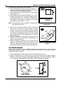
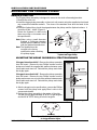
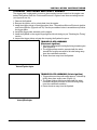
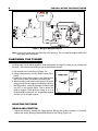
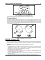
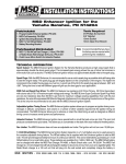
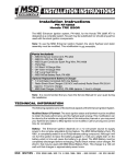
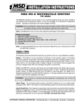
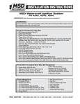
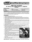
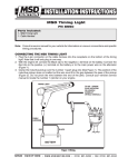
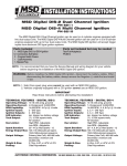
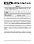
INSTALLATION INSTRUCTIONS MSD Ignition System, PN KT4151 Important: Read the instructions completely before attempting the installation. Parts Included: 1 - MSD Ignition Control, PN 4151 1 - Pro-CD Coil, PN 42951 1 - Trigger Pickup 1 - Rare Earth Magnet 1 - On/Off Switch 1 - Timing Tape 1 - NiCad Battery Wiring Harness 1 - Parts Bag Not Included, but Required: 2 - 7.2 Volt NiCad Batteries Special Materials/Tools: Depth Micrometer Drill (Briggs & Stratton Only) 0.377" Drill Bit (Briggs & Stratton Only) JB Weld Compound Dial Indicator C-Clamp Note: Installation of this kit requires machining the flywheel on Briggs & Stratton engines only. Note: It is recommended to have the Service Manual for your engine during the installation. TECHNICAL INFORMATION The following information will give you a better idea of how the MSD Ignition System and each of its components operates. MSD Ignition Control: This is a capacitive discharge (CD) ignition which generates a high voltage and delivers it to the ignition coil (primary voltage). An LED indicator aids in setting the ignition timing. Ignition Coil: The MSD Pro-CD Coil produces over 30,000 volts with a minimum supply of 10 volts to the Ignition Control. Trigger Magnet: This magnet creates the trigger signal as it passes over the pickup. It is made of Rare Earth material, the strongest, and longest lasting magnet material available. MODIFYING THE FLYWHEEL BRIGGS AND STRATTON ENGINES Briggs and Stratton engines require drilling the flywheel to install the trigger magnet. It is an important procedure and must be accurately performed. A template is included that gives you the correct positioning of the magnet. There are two options; one position for engines running gasoline, and another for engines using alcohol. Figure 1 Preparing the Flywheel. MSD IGNITION Figure 2 Marking Magnet Holes. 12120 ESTHER L AMA, SUITE 114, EL PASO, TEXAS, 79936 (800) 392-2842 FAX (915) 858-9241 2 INSTALLATION INSTRUCTIONS 1. Remove the flywheel from the crankshaft. 2. Position the flywheel with the engine side facing up. Locate the magnet positioning template, line up the slots and tape it to the flywheel (Figure 1). 3. Using a center punch, mark the location of the magnet mount (Figure 2). 4. The magnet mount is to be 0.125" deep (0.110" - 0.140"). Drill the hole using a 0.377" V-drill bit, stopping to take measurements (Figure 3). Do not drill too deep. Push the magnet into the mount to make sure it sits flush with flywheel surface within +/- 0.015". Note: The magnet has one side marked. This side must face towards the pickup. 5. Remove the magnet and clean the hole and magnet with alcohol or electrical contact cleaner. Using a permanent epoxy such as JB Weld, fill the hole about half way. Insert the magnet into the hole with the marked side facing out towards the engine. Push the magnet down until it sits flush with the flywheel surface. Wipe off the excess epoxy. 6. Using a C-clamp and a small piece of wood, clamp the magnet into position and let dry completely to the epoxys recommendations. 7. When the flywheel assembly is cured, make sure the magnet is flush with the surface, smooth and clean (Figure 4). Reinstall the flywheel using the stock key on the crankshaft and torque to the factory specifications. Figure 3 Measuring the Magnet Mounting Hole. Figure 4 The Magnet Mounted in the Flywheel. TECUMSEH ENGINES When using the flywheel from a "POINTS Ignition" the magnets that are in place from the factory work fine and no magnet or flywheel modifications need to be done when used with the MSD "Hall Effect" system. 1. Viewing the flywheel from backside, position flywheel keyway at 12:00. 2. Apply a small amount of a quality epoxy to the unmarked side of the supplied magnet. Position it on the inside diameter of the flywheel between the 3:00 and 4:00 position (Figure 5). The magnet center should be placed .600" in from back edge of flywheel. Figure 5 Magnet Placement for Tecumseh Engines. MSD IGNITION 12120 ESTHER L AMA, SUITE 114, EL PASO, TEXAS, 79936 (800) 392-2842 FAX (915) 858-9241 INSTALLATION INSTRUCTIONS 3 MOUNTING THE TRIGGER PICKUP BRIGGS & STRATTON The Trigger pickup assembly is designed to mount in the stock coil mounting brackets. 1. Remove the stock coil. 2. Install the trigger pickup assembly on the stock coil mounts using the supplied socket head cap screws and belleville washers. The dome of the washers must face the head of the bolts. 3. Install the flywheel then check the airgap between the pickup and the flywheel surface. It should be 0.030" - 0.095" (Figure 5). Rotate the flywheel to make sure there are no high or low areas out of the specification. Note: When using a small diameter flywheel, a coil/trigger relocator bracket must be obtained. Check with the flywheel manufacturer. Note: The flywheel must be torqued to the factory specification when checking the pickup airgap. Figure 6 Checking the Air Gap of the Flywheel and Trigger Pickup. ADJUSTING THE AIRGAP ON BRIGGS & STRATTON ENGINES If the gap is less than 0.030": Remove the pickup assembly from the mount. Remove the two Phillips screws from the pickup and install the supplied #4 washers between each mount plate and stand off. Reinstall the pickup and check the airgap again. If the gap is more that 0.095": Remove the pickup assembly from the mount. Remove the two Phillips screws from the pickup and remove one or both of the washers between each mount plate and stand off. Reinstall the pickup and check the airgap again. 4. After the airgap is set to specifications, remove the Phillips screws from the pickup and apply Blue Loctite to the screws and reinstall. 5. Position the pickup assembly in the center of the slots. This will give you approximately 19° BTDC for gas engines and about 34° BTDC timing for alcohol engines. Figure 7 Adjusting the Airgap. Figure 8 Positioning the Pickup Assembly of a Briggs & Stratton Engine. MSD IGNITION 12120 ESTHER L AMA, SUITE 114, EL PASO, TEXAS, 79936 (800) 392-2842 FAX (915) 858-9241 4 INSTALLATION INSTRUCTIONS TECUMSEH "ELECTRONIC AND POINTS" ENGINES. The trigger plate is designed to mount on the mounting bosses located on the engine case behind the flywheel. Both the "Points and Electronic" engines have these mounting bosses (see figures 9 and 10). 1. Remove the flywheel. 2. Remove the ignition coil or points plate from the engine. 3. Install the trigger pickup to the trigger plate. Note: The position differs on Electronic ignition and Points ignitions (Figure 9 and 10). See the procedures below to assemble and position the trigger plate. 4. Install the trigger plate assembly on the engine. 5. Install the flywheel on the engine finger tight and check timing as per "Checking the Timing" section. 6. Inspect the trigger pickup air gap after torquing the flywheel to specs. TRIGGER PLATE ASSEMBLY (Electronic Ignition) 1. Must be installed with mounting lip facing toward engine case (Figure 9). 2. The trigger pickup must be mounted with the wires towards the engine case with its flat side facing away from the crankshaft centerline. 3. Route the wires away from the flywheel. Figure 9 Trigger Installed on an Electronic Ignition Engine. TRIGGER PLATE ASSEMBLY (Points Ignition) 1. Trigger plate must be positioned at approx. 2:00 with lip facing away from engine case (Figure 10). 2. The trigger pickup must be mounted with the wires toward the engine case with its flat side facing away from the crankshaft centerline. 3. Route the wires away from the flywheel. Figure 10 Trigger Installed on a Points Ignition Engine. MSD IGNITION 12120 ESTHER L AMA, SUITE 114, EL PASO, TEXAS, 79936 (800) 392-2842 FAX (915) 858-9241 INSTALLATION INSTRUCTIONS 5 MOUNTING IGNITION The Ignition may be mounted in any position away from direct engine heat sources. Before mounting, make sure all of the wires reach their proper connections. Use the ignition as a template and mark the two mounting holes. Drill the holes and mount the Ignition using the supplied #10 screws. COIL Use the supplied screws to mount the coil. The coil is encased in an epoxy compound to protect the windings from moisture and vibration. Connect the supplied jumper from the BLACK (negative) coil wire to the engine crankcase for ground. Note: Failure to connect this wire will damage the ignition. ON/OFF SWITCH Mount the On/Off switch in a position within easy reach of the driver. Drill a 1/2" hole and install the switch using the supplied hardware. BATTERY A battery is not supplied but is required with the MSD. You also must provide a bracket and hold down. There are two battery choices; a 12 volt sealed lead acid battery or two 7.2V Nicad Battery Packs (standard hobby RC batteries) connected in series. The 12 volt battery must be a leak-proof DOT and IATA approved battery such as the Panasonic LCR 12V4BP. This battery will give you approximately four hours of run time and must be recharged by the manufacturers trickle charge specification. Two 7.2V Nicad Battery Packs can be used in series to provide a run time of approximately two hours. Note: Always disconnect the battery from the ignition before charging. WIRING With all of the components mounted and the battery charged, connect the wiring. Figure 8 shows the correct wiring. 1.The PINK, BLACK and WHITE wires connect to the weathertight connector coming from the trigger pickup. 2. Connect the BROWN wire to the coil negative (BLACK) wire. 3. Connect the ORANGE wire to the coil positive (ORANGE) wire. 4. Connect the RED wire from the On/Off switch, to the battery positive terminal. 5. Connect the BLACK wire to battery ground. 6. The BROWN jumper should be connected to the coil negative (BROWN) wire and engine ground. MSD IGNITION 12120 ESTHER L AMA, SUITE 114, EL PASO, TEXAS, 79936 (800) 392-2842 FAX (915) 858-9241 6 INSTALLATION INSTRUCTIONS Figure 11 Wiring the MSD Ignition System. Note: Connect the spark plug wire from the coil to the plug. Do not crank the engine without the spark plug wire connected. CHECKING THE TIMING A timing mark can be made anywhere near the flywheel as long as it is easy to see, steady and accurate. We recommend drilling a hole in the flywheel shroud. 1. Drill a small hole in the shroud (Figure 12). 2. Using a dial indicator, find Top Dead Center of the piston. 3. Install the correct timing tape to the flywheel with the 0 lined up with your reference timing mark. 4. With the battery connected to the ignition, the spark plug grounded to the engine case and the switch in the ON position, rotate the flywheel clockwise until the LED on the Ignition lights. This is where the ignition triggers. Note what the timing is at. It is recommended to have 18° - 20° for gasoline engines and 33°-34° for alcohol engines. Figure 12 Timing Marks. ADJUSTING THE TIMING BRIGGS AND STRATTON 1. Adjust the timing by moving the trigger pickup. Moving the pickup clockwise, or forward, retards the timing. Moving it backwards advances the timing (Figure 13). MSD IGNITION 12120 ESTHER L AMA, SUITE 114, EL PASO, TEXAS, 79936 (800) 392-2842 FAX (915) 858-9241 INSTALLATION INSTRUCTIONS 7 Figure 13 Adjusting the Timing on a Briggs and Stratton. After each timing adjustment, tighten the pickup and recheck the timing. TECUMSEH ENGINE To adjust the timing, the flywheel must be removed. To check the timing, a wire pointer can be fabricated and utilized with the Timing Tape and the LED of the MSD Ignition. With this setup, the timing can be checked without the engine running. When the bolts are placed in the middle of the slots on the trigger plate the timing will be approximately 35° BTDC. Note: The max retard is 25° and the max advance is 45°. Figure 14 Adjusting the Timing on a Tecumseh ENGINE TUNING TIPS Due to the increased output of the MSD, tuning the engine will be required. After each adjustment, test drive the vehicle and read the spark plug for signs of detonation or rich or lean fuel mixtures. WARNING: Always disconnect the battery before working on the engine. On Briggs & Strattons, start with the timing at 18° BTDC for gasoline (the trigger plate will be slightly right of center) and 33° for alcohol engines. Adjust the timing in small increments followed by test runs until the best performance is achieved. The plug gap may be opened to 0.040". The engine will run faster by leaning the mixture out at high rpm. High speed backfires can usually be attributed to a rich fuel mixture. Check the temperature and condition of the plug after a wide open run while shutting the engine off at speed. After every track session, inspect all of the ignition components, fasteners and wiring. MSD IGNITION 12120 ESTHER L AMA, SUITE 114, EL PASO, TEXAS, 79936 (800) 392-2842 FAX (915) 858-9241 8 INSTALLATION INSTRUCTIONS TECH NOTES ________________________________________________________________________________________________________________________ ________________________________________________________________________________________________________________________ ________________________________________________________________________________________________________________________ ________________________________________________________________________________________________________________________ ________________________________________________________________________________________________________________________ ________________________________________________________________________________________________________________________ ________________________________________________________________________________________________________________________ ________________________________________________________________________________________________________________________ ________________________________________________________________________________________________________________________ ________________________________________________________________________________________________________________________ ________________________________________________________________________________________________________________________ ________________________________________________________________________________________________________________________ ________________________________________________________________________________________________________________________ ________________________________________________________________________________________________________________________ ________________________________________________________________________________________________________________________ ________________________________________________________________________________________________________________________ Service In case of malfunction, this MSD component will be repaired free of charge according to the terms of the warranty. When returning MSD components for service, Proof of Purchase must be supplied for warranty verification. After the warranty period has expired, repair service is charged based on a minimum and maximum charge. Send the unit prepaid with proof of purchase to the attention of: Customer Service Department, Autotronic Controls Corporation, 12120 Esther Lama, Suite 114, El Paso, Texas 79936. When returning the unit for repair, leave all wires at the length in which you have them installed. Cutting wires close to the unit will void your warranty. Be sure to include a detailed account of any problems experienced, and what components and accessories are installed on the vehicle. The repaired unit will be returned as soon as possible after receipt, COD for any charges. For more information, call the MSD Customer Service Line 1(800) 392-2842. MSD technicians are available from 8:00 a.m. to 5:00 p.m. Monday - Friday (mountain time). A Limited Warranty utotronic Controls Corporation warrants MSD Ignition products to be free from defects in material and workmanship under normal use and if properly installed for a period of one year from date of purchase. If found to be defective as mentioned above, it will be replaced or repaired if returned prepaid along with proof of date of purchase. This shall constitute the sole remedy of the purchaser and the sole liability of Autotronic Controls Corporation. To the extent permitted by law, the foregoing is exclusive and in lieu of all other warranties or representations whether expressed or implied, including any implied warranty of merchantability or fitness. In no event shall Autotronic Controls Corporation be liable for special or consequential damages. MSD IGNITION MSD IGNITION FRM18942 12120 ESTHER L AMA, SUITE 114, EL PASO, TEXAS, 79936 (800) 392-2842 FAX (915) 858-9241 12120 ESTHER L AMA, SUITE 114, EL PASO, TEXAS, 79936 (800) 392-2842 FAX (915) 858-9241 Revised 09/97 Printed In U.S.A.