1
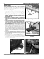
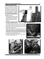
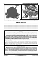
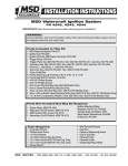
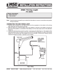
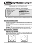
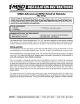
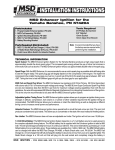
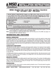
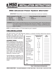
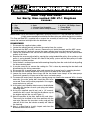
MSD Cap and Rotor
for Early, Non-vented GM LT-1 Engines
PN 8481
Parts Included:
1 - Cap
1 - Rotor
1 - Isolator
2 - Rotor Screws
2 - Seals
1 - Vacuum Line Assembly
4 - 3.5mm x 6mm Phillips Screws
1 - 8-32 x 1.125 Phillips Screw
1 - Clamp-Block
1 - Removal Tool
IMPORTANT: Due to the number of applications and years that the LT-1 Cap and Rotor are used on, it
is highly recommended to have the Service Manual for your vehicle during this installation.
This Cap and Rotor Kit is supplied with a vacuum line assembly to vent the cap. This helps prevent
ozone and moisture build-up within the distributor cap.
DISASSEMBLY
1.
2.
3.
4.
5.
Disconnect the negative battery cable.
Locate the radiator petcock and drain the coolant from the system.
Disconnect the MAF and IAC sensors. Remove the air intake ductwork and the MAF sensor.
Once the coolant is drained, remove the upper radiator hose from the thermostat housing.
Loosen the three bolts that secure the crankshaft pulley/hub assembly. Do not remove them
entirely at this time.
6. Remove the accessory drive belt by moving the spring loaded idler pulley. Use caution as this
pulley is spring loaded! The belt will slide off the pulley system and the idler pulley will settle
beyond its installed position.
7. Once the belt is removed, proceed with removing the pulley from the crankshaft hub by pulling
the three retaining bolts.
8. It may be necessary to remove the cooling fan. This is done by removing the four bolts and
disconnecting the wiring connection.
9. Disconnect the air pump power wires and remove the air pump from its mounting brackets.
10. Disconnect the coolant temperature wiring sensor located on the water pump.
11. Loosen the lower radiator hose clamp and the two heater hose clamps at the water pump.
Coolant will generally still pour out of the hoses and water pump.
12. To remove the water pump, the power steering pump may need to be removed. With a shorter
extension, the water pump bolt should be able to be
accessed. There are five water pump bolts. Once again,
more coolant may spill out.
13. At this point, you should be able to access the distributor
cap. Mark the location of each spark plug wire before
removing them.
14. Using the supplied special tool and a 1/4" wrench,
remove the four screws that hold the distributor cap to
the engine and pull the cap off (Figure 1).
15. Note the position of the rotor, optical disk and shims.
These must be installed in the same position with the
new rotor. Remove the two rotor screws and pull the
rotor off. At this time, the isolator assembly will slide off
the housing.
16. Now is a good time to visually inspect and clean the
distributor for excessive wear.
Figure 1 Removing the Original Cap.
MSD IGNITION • 1490 HENRY BRENNAN DR., EL PASO, TEXAS 79936 • (915) 857-5200 • FAX (915) 857-3344
2
INSTALLATION INSTRUCTIONS
INSTALLATION
Before proceeding, you will need to seal the distributor
housing's original vent holes. These are located at the
bottom of the distributor housing (Figure 2). Use a silicone
gasket sealer or equivalent.
1. Locate and install the distributor-to-isolator seal then
position the isolator in place on the distributor (Figure
3). Note the fresh air inlet port on the isolator (Figure 4).
2. Make sure the optical disk and shims are installed in the
right position, then install the new rotor with the supplied
hardware. The rotor only installs one way. Make sure it sits
squarely on the shaft.
3. Make sure that the Isolator-to-Cap seal is installed on the
Isolator, then install the cap using the supplied Phillips head
screws.
4. Locate four metric Phillips screws that retain the cap assembly.
There is also a standard, slightly larger and longer Phillips
screw. This screw is used with the Clamp-Block that goes in
the cap tab located between the wiring harness and the coil
wire tower (Figure 5).
5. Note that the Clamp-Block has two different thicknesses
(Figure 6). Some distributor housings have a machined
surface while others are cast. Determine which side works
best in your application to secure the top mount of the cap.
Once the direction is achieved, slide the Clamp-Block into
position and screw the standard Phillips screw into position
(Figure 6).
6. Connect the distributor connector followed by the coil wire
and spark plug wires. Ensure that each wire is in the correct
location (Figure 10).
7. Install Vacuum hoses as shown on page 3 (Figures 7 - 9).
8. The distributor is assembled. Reinstall all of the components
in the reverse order. It is recommended to follow along with
your vehicle’s service manual.
SEAL THREE
HOLES WITH
SILICON SEALER
OR EQUIVALENT.
Figure 2 Sealing the Vent Holes.
SEAL
ADD SILICON
SEALER BENEATH
CONNECTOR
Figure 3 Installing the Distributorto-Isolator Seal.
FRESH AIR INLET
Figure 4 Isolator Inlet.
Figure 5 Clamp-Block Mounting Boss.
MSD IGNITION • 1490 HENRY BRENNAN DR., EL PASO, TEXAS 79936 • (915) 857-5200 • FAX (915) 857-3344
INSTALLATION INSTRUCTIONS
3
VACUUM LINE ROUTING
This kit is supplied with a vacuum
EDGE
MUST SIT
line kit that will aid in venting the
FLUSH
distributor cap. One hose assemWITH
HOUSING
bly connects to a vacuum port on
the intake manifold while the other
NOTE
line connects to the air inlet going
DIFFERENT
THICKNESSES
into the throttle body. In order to
take advantage of this venting technique, you will need to seal the three
small holes on the bottom of the
distributor (Figure 2).
1. Connect the long hose assembly
to the lower vacuum inlet of the
MSD distributor cap (Figure 7).
Use the supplied clamp to secure
the hose.
2. Route the vacuum line around
the side of the engine and up to
Figure 6 Installing the Clamp-Block.
the intake manifold. Splice into
the hose that connects just over the PCV valve (Figure
8). Also note the check valve that is in-line. The black
LOWER VACUUM
side of the valve must face towards the vacuum source.
INLET
3. Connect the smaller vacuum line to the fresh air inlet port
of the isolator (see Figure 4).
4. Locate the supplied 90° vacuum nipple. Using a 3/16"
drill bit, drill a hole in the air intake duct and install the
nipple (Figure 9). Make sure the barb goes through and
into the duct. Connect the line from the distributor cap to
this inlet. This line completes the fresh air circulation
through the distributor cap (Figure 11).
5. Install the spark plug wires ensuring they are routed to
the correct terminal (Figure 10).
Figure 7 Install the Lower Vacuum Line.
VACUUM
SOURCE
FRESH AIR
SOURCE
CHECK
VALVE
Figure 8 Connecting the Vacuum Source.
Figure 9 Installing the Fresh Air Line.
MSD IGNITION • 1490 HENRY BRENNAN DR., EL PASO, TEXAS 79936 • (915) 857-5200 • FAX (915) 857-3344
4
INSTALLATION INSTRUCTIONS
COIL WIRE
4
5
6
3
8
7
2
1
FRESH AIR INLET
Figure 10 Spark Plug Wire Location.
VACUUM LINE: Route behind
plug wires and pump up to
intake manifold connection.
Figure 11 Fresh Air Hose Routing.
TECH NOTES
________________________________________________________________________________________________________________________
________________________________________________________________________________________________________________________
________________________________________________________________________________________________________________________
________________________________________________________________________________________________________________________
________________________________________________________________________________________________________________________
________________________________________________________________________________________________________________________
Service
In case of malfunction, this MSD component will be repaired free of charge according to the terms of
the warranty. When returning MSD components for service, Proof of Purchase must be supplied for warranty
verification. After the warranty period has expired, repair service is charged based on a minimum and
maximum charge.
All returns must have a Return Material Authorization (RMA) number issued to them before being
returned. To obtain an RMA number please contact MSD Customer Service at (915) 855-7123 or fax a
request to (915) 857-3344. Send the unit prepaid with proof of purchase to the attention of: MSD Ignition,
Customer Service - RMA #, 12120 Esther Lama, Dock 5, El Paso, Texas 79936.
When returning the unit for repair, leave all wires at the length in which you have them installed. Be sure
to include a detailed account of any problems experienced, and what components and accessories are
installed on the vehicle.
The repaired unit will be returned as soon as possible after receipt, COD for any charges. (Ground
shipping is covered by warranty). All units are returned regular UPS unless otherwise noted. For more
information, call the MSD Customer Service Line (915) 855-7123. MSD technicians are available from 7:00
a.m. to 6:00 p.m. Monday - Friday (mountain time).
Limited Warranty
M
SD IGNITION warrants MSD Ignition products to be free from defects in material and workmanship
under normal use and if properly installed for a period of one year from date of purchase. If found to be
defective as mentioned above, it will be replaced or repaired if returned prepaid along with proof of date
of purchase. This shall constitute the sole remedy of the purchaser and the sole liability of MSD Ignition. To
the extent permitted by law, the foregoing is exclusive and in lieu of all other warranties or representations
whether expressed or implied, including any implied warranty of merchantability or fitness. In no event
shall MSD Ignition be liable for special or consequential damages.
MSD IGNITION • 1490 HENRY BRENNAN DR., EL PASO, TEXAS 79936 • (915) 857-5200 • FAX (915) 857-3344
MSD IGNITION • 1490 HENRY BRENNAN DR., EL PASO, TEXAS 79936 • (915) 857-5200 • FAX (915) 857-3344
© 2005 AUTOTRONIC CONTROLS CORPORATION
FRM27073
Created 09/05
Printed in U.S.A.