1
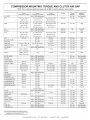
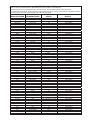
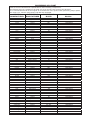
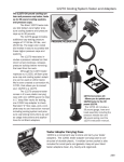
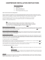
COMPRESSOR INSTALLATION INSTRUCTIONS
Always Practice Safety First!
❑
Air Bags (Caution)
❑
No Smoking
❑
Wear Eye Protection
❑
Work in a well ventilated area
❑
Wear Skin Protection (gloves)
❑
Recover refrigerant before making repairs
Follow all Federal, State and Local Regulations.
Proper A/C performance is dependent on all systems performing properly. Make certain that the engine cooling system is at peak
operation, and that the cooling fan / fan clutch is operating properly. Worn belts, idlers and tensioners can cause poor cooling system
performance due to belt slippage. Low voltage at the A/C clutch assembly can cause premature compressor failure.
Contaminated refrigerant continues to be one of the most significant problems facing the A/C service industry
today. Use a refrigerant identifier to verify that the refrigerant in the system is not contaminated with a blend
refrigerant or has a high concentration of air.
Tip!!!
When mounting the replacement compressor to the vehicle, the compressor must fit or rest with
even contact at each mounting point. Warped brackets must be completely straightened or replaced.
Leave mounting bolts loose until all bolts are in place. Tighten bolts equally according to torque specs
for that specific compressor. Do Not Over-Tighten. (Over-Tightening Causes Leaks)
Replace the Filter Drier or Accumulator
All Filter Driers and Accumulators contain a desiccant material. This material is designed to absorb the moisture that has seeped into
the A/C system. Moisture in an A/C system can form corrosive contaminates that will cause rapid system failure. It is very important to
remove all moisture from the A/C system before charging.
REPLACE OR INSPECT THE CONTROL DEVICES
The orifice tube is a control and filter device for accumulator systems, and should always be replaced to ensure proper refrigerant
and oil flow through the system. The thermal expansion valve is the control device for systems using a receiver/drier. It should be
examined and replaced, if found to be contaminated.
A Clean A/C System is Imperative
When a compressor fails, tiny internal particles mix with oil and spread throughout the entire system. This contaminated oil, as well as
moisture and other corrosives must be removed to avoid premature failure of the replacement compressor. Clean the entire system
thoroughly with an effective cleaning agent and/or replace contaminated parts. Air alone does not remove contaminants. Two methods
used today are effective in removing oil and contaminants:
(1) liquid cleaning with an effective cleaning agent
Flushing with Dura Flush II or similar non-oil based flush designed specifically for automotive A/C use, is a proven method to clean A/C
system components when used with a flush cylinder and pressurized air.
Closed loop flushing with a power flush machine and the machine manufacturer’s approved solvent is an effective method to clean A/C
system components. This cleaning method is utilized by several major OE service providers.
(2) closed loop power cleaning using a refrigerant.
Note
Newer condenser designs are difficult, if not impossible to thoroughly clean, and in many cases must be
replaced.
Proper Evacuation
The A/C system must be free of moisture and air to work properly. Removing the air and moisture with an
A/C system vacuum pump for a minimum of forty-five minutes to an hour, is necessary to deliver proper
long lasting A/C performance.
Lubrication
The only moving component in the A/C system is the compressor, and adequate lubrication is critical. If oil or refrigerant charges are
incorrect, internal damage to the compressor will occur! If uncertain about the proper lubricant type or amount, refer to the Capacities
Guide, the under hood decal, or an O.E. service manual.
To ensure proper compressor lubrication, install half the required system oil in the suction side. This may require turning the compressor
shaft as the oil is installed. The remaining amount of required system oil should be installed in the accumulator or low side of the system.
To ensure that the front seal is lubricated and does not leak, after the oil is installed, the compressor must be placed or held with the
front seal down for 1 to 3 minutes, to allow oil to coat the seal. If this seal is not lubricated before installation, refrigerant may leak.
REMEMBER!!!
Compressors are shipped with assembly lube or ICE 32. DO NOT DRAIN. Add the correct type and amount of lubricant
per specific system specifications.
Use only the recommended Refrigerant Type and Amount
Only R12 or R134a can be used to maintain proper system performance. The correct amount of charge is critical for
system efficiency and durability, because the refrigerant carries the lubricant through the system. Specifications can
be found in the Capacities Guide, the under hood decal or an O.E. service manual.
Tip!!!
Dual A/C systems require additional refrigerant and oil, check vehicle specifications.
Compressor Rotation
Always rotate the compressor shaft at least 10 revolutions after the hoses are connected and prior to starting the engine. This will pump
the excess liquid lubricant out of the compressor cylinders and into the system.
Clutch
Clutch coil voltage should be within one volt of system operating voltage. Anything less weakens the magnetic force of the clutch
allowing slippage, increased heat, and failure. Clutch air gap (between hub and pulley) is important and should be checked before
installation to ensure no changes have occurred during shipping and handling. Ask your suppliers for air gap specifications.
TIP!!!
After installation, with the engine idling, switch the compressor off and on 10 to 12 times. This will burnish the hub and
pulley face removing any machining glaze or rust inhibitors and enhance complete surface contact.
Verify the Repair
Use an electronic leak detector or fluorescent dye to check for leaks. A leak will cause system failure. When repairs are finished,
ensure that the job is done right the first time by doing temperature drop testing.
Suggested A/C tools & equipment:
A/C O-Ring Lube
Charging Cylinder
Gauge Set
Leak Detector
Refrigerant Identifier
Spanner Wrench
Vacuum Pump
This compressor is warranted to be free from defects in materials and workmanship at the time of its manufacture. See your supplier
for details of the terms and conditions of this warranty.
Temperature Control Division
1801 Waters Ridge Dr.
Lewisville, TX 75057
*Tech Tips can be found at www.4s.com
COMPRESSOR OIL CHART
Refer to the O.E. Manufacturer's Specifications when installing a compressor.
The following chart is a guideline to be used only if you do not have access to the OE specs.
It is recommended that all of the original oil be flushed out of the system when performing major repairs.
This chart is for vehicles using R134a, both OE and retrofitted.
VEHICLE
MANUFACTURER
COMPRESSOR
MANUFACTURER
COMPRESSOR
MODEL
All
Acura
Alfa Romeo
Alfa Romeo
Audi
Audi
Audi
BMW
BMW
BMW
BMW
Chrysler
Chrysler
Chrysler
Chrysler
Chrysler
Jeep / Eagle
Jeep / Eagle
Jeep / Eagle
Citroen
Citroen
Citroen
Ferrari
Fiat
Fiat
Ford
Ford
Ford
Ford
Ford
Ford
Ford
Ford
Ford
G.M.
G.M.
G. M.
G.M.
G.M.
G.M.
G.M.
G.M.
Geo
G.M. Saturn
G.M. Saturn
G.M.
Honda
Honda
Honda
Honda
Hyundai
Hyundai
Infinity
Infinity
Infinity
Isuzu
Isuzu
Isuzu
Isuzu
J. I. Case
Jaguar
Hybrid Vehicle
Nippondenso
Sanden
Nippondenso
Diesel Kiki/Zexel
Nippondenso
Sanden
Seiko Seiki
Nippondenso
Bosch / Behr
Bosch / Behr
Nippondenso
Nippondenso
Sanden
Sanden
Mitsubishi
Sanden
Sanden
Nippondenso
Sanden
Sanden
Harrison
Sanden
Sanden
Nippondenso
Ford
Nippondenso
Sanden
Panasonic
Ford
Harrison
Sanden
Ford
Ford Scroll
Delphi / Harrison
Delphi / Harrison
Four Seasons
Delphi / Harrison
Delphi / Harrison
Nippondenso
Sanden
Sanden
Nippondenso
Diesel Kiki/Zexel
Diesel Kiki/Zexel
Harrison
Sanden
Sanden
Nippondenso
Nippondenso
Ford
Halla
Zexel
Calsonic
Zexel
Zexel
G.M.
Diesel Kiki/Zexel
Diesel Kiki/Zexel
Sanden
Sanden
10P
SDV
SC8
DCW
10P
SDV
SS
10P
Wing
Axial
10PA
6C / 6CA
TR / TRS
SD
FX
SD
TR
10P / 10PA
SD7
SDV
V5
SDV
SD7
SC8
FS10 / FX15
10P / 10PA
SD
Rotary
FS6
A6
TR, TRS
FS-18, FS-20
V5 Retro
V5 R134a
88 series HR6 / HD6 / HT6
HR6 / HD6 / HT6
R4
10PA
SD7
SD5
10PO
DKV
DCV
CVC
TR
SD
10P
HADSYS. 7 Cyl.
FX15 / FS10
FX15 / FS10/HS-15,17,18,20
CVW
V5
KC50
Rotary
SD
SD7H
Part
Number
59889/409610
59007/409503
59007/409503
59007/409503
59007/409503
59007/409503
59007/409503
59007/409503
59007/409503
59007/409503
59003/409501
59007/409503
59007/409503
59007/409503
59002/409502
59007/409503
59002/409502
59007/409503
59007/409503
59002/409502
59007/409503
59003/409501
59007/409503
59002/409502
59007/409503
59007/409503
59007/409503
59002/409502
59007/409503
59007/409503
59003/409501
59007/409503
59007/409503
59007/409503
59003/409501
59003/409501
59007/409503
59003/409501
59003/409501
59007/409503
59002/409502
59002/409502
59007/409503
59003/409501
59003/409501
59003/409501
59007/409503
59002/409502
59007/409503
59007/409503
59007/409503
59007/409503
59003/409501
59007/409503
59007/409503
59007/409503
59007/409503
59003/409501
59007/409503
59002/409502
59002/409502
COMPRESSOR OIL CHART
Refer to the O.E. Manufacturer's Specifications when installing a compressor.
The following chart is a guideline to be used only if you do not have access to the OE specs.
It is recommended that all of the original oil be flushed out of the system when performing major repairs.
This chart is for vehicles using R134a, both OE and retrofitted.
VEHICLE
MANUFACTURER
COMPRESSOR
MANUFACTURER
COMPRESSOR
MODEL
Jaguar
John Deere
Lamborghini
Lancia
Mack
Land Rover
Land Rover
Lexus
Lotus
Mazda
Mazda
Mazda
Mazda
Mazda
Mercedes
Mercedes
Mercedes
Mercedes
Mercedes
Mitsubishi
Mitsubishi
New Holland
Nissan
Nissan
Nissan
Nissan
Opel
Opel
Opel
Peterbilt
Peugeot
Peugeot
Porsche
Peugeot
Renault
Renault
Renault
Renault
Rolls Royce
Rover
Rover
Rover
Saab
Saab
Saab
Seat
Skoda
Subaru
Subaru
Suzuki
Suzuki
Toyota
Toyota
Vauxhaul (GM)
Volkswagen
Volkswagen
Volkswagen
Volkswagen
Volvo
Volvo
Sanden
Nippondenso
Sanden
Sanden
Sanden
Sanden
Sanden
Nippondenso
Sanden
Panasonic
Nippondenso
Ford
Sanden
Zexel
Harrison
Nippondenso
Nippondenso
Sanden
York
Mitsubishi
Nippondenso
Sanden
Diesel Kiki/Zexel
Calsonic
Diesel Kiki/Nihon
Diesel Kiki/Zexel
Delphi / Harrison
Nippondenso
Sanden
Sanden
Sanden
Sanden
Nippondenso
Sanden
Sanden
Sanden
Sanden
Zexel
Sanden
Sanden
Sanden
Nippondenso
Seiko Seiki
Sanden
Nippondenso
Sanden
Sanden
Zexel
Diesel Kiki
Sanden
Nippondenso
Nippondenso
Nippondenso
Delphi / Harrison
Sanden
Sanden
Sanden
Zexel
Seiko Seiki
Sanden
SD
10P
SD7
SD7
SD
TRS
SD7
10PA
SD
Rotary
TV
FS10
SD
A6, R4
6CA
10P / 10PA
SD6V
FX / MSC
10P / 10PA
SD
DKV / DCV
Rotary
DKS / Rotary
DKV / Rotary
V5
6CA
7SB
SD
SD
SDV
10P
SD7
SDV
SD7
TRS
DKS-15CH
SDV
SD7
SDV
10P
SS
7SB
SDV
SD7
Rotary
15CH
SD
10P
10P / 10PA
TV
V5
SD / SD7
SDV
7SB
DCW
SS
SD / SD7
Part
Number
59002/409502
59007/409503
59002/409502
59002/409502
59002/409502
59007/409503
59002/409502
59007/409503
59007/409503
59007/409503
59002/409502
59007/409503
59002/409502
59007/409503
59003/409501
59007/409503
59007/409503
59007/409503
59009/409500
59007/409503
59007/409503
59007/409503
59003/409501
59007/409503
59007/409503
59003/409501
59003/409501
59007/409503
59007/409503
59002/409502
59002/409502
59007/409503
59007/409503
59002/409502
59007/409503
59002/409502
59007/409503
59007/409503
59007/409503
59002/409502
59007/409503
59007/409503
59007/409503
59009/409500
59007/409503
59007/409503
59002/409502
59003/409501
59007/409503
59002/409502
59007/409503
59007/409503
59002/409502
59003/409501
59002/409502
59007/409503
59007/409503
59007/409503
59007/409503
59002/409502