1
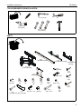
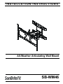
INSTALLATION INSTRUCTIONS
Instrucciones de instalación
Installationsanleitung
Instruções de Instalação
Istruzioni di installazione
Installatie-instructies
Instructions d´installation
All-Weather Articulating Wall Mount
Spanish Product Description
German Product Description
Portuguese Product Description
Italian Product Description
Dutch Product Description
French Product Description
SB-WM46
SB-WM46
Installation Instructions
DISCLAIMER
SunBriteTV LLC (SBTV) intend to make this manual accurate
and complete. However, SBTV makes no claim that the
information contained herein covers all details, conditions or
variations, nor does it provide for every possible contingency in
connection with the installation or use of this product. The
information contained in this document is subject to change
without notice or obligation of any kind. SBTV makes no
representation of warranty, expressed or implied, regarding the
information contained herein. SBTV assumes no responsibility
for accuracy, completeness or sufficiency of the information
contained in this document.
WARNING: Use this mounting system only for its intended
use as described in these instructions. Do not use
attachments not recommended by the manufacturer.
WARNING: Never operate this mounting system if it is
damaged. Return the mounting system to a service center for
examination and repair.
IMPORTANT ! : The SB-WM46 mounts are designed to be
mounted to a 2" x 4" wood studs (16" on center) wall or to an 8"
concrete wall.
--SAVE THESE INSTRUCTIONS-SunBriteTV® is a registered trademark of SunBrite TV LLC.
Built to SunBriteTV® specifications by Chief Manufacturing. All
rights reserved.
IMPORTANT SAFETY INSTRUCTIONS
WARNING: A WARNING alerts you to the possibility of
serious injury or death if you do not follow the instructions.
CAUTION: A CAUTION alerts you to the possibility of
damage or destruction of equipment if you do not follow the
corresponding instructions.
WARNING: Failure to read, thoroughly understand, and
follow all instructions can result in serious personal injury,
damage to equipment, or voiding of factory warranty! It is the
installer’s responsibility to make sure all components are
properly assembled and installed using the instructions
provided.
WARNING: Failure to provide adequate structural strength
for this component can result in serious personal injury or
damage to equipment! It is the installer’s responsibility to
make sure the structure to which this component is attached
can support five times the combined weight of all equipment.
Reinforce the structure as required before installing the
component. The wall to which the mount is being attached
may have a maximum drywall thickness of 5/8" (1.6cm). Do
not install drywall anchors into the seam between drywall
pieces.
WARNING: Exceeding the weight capacity can result in
serious personal injury or damage to equipment! It is the
installer’s responsibility to make sure the combined weight of
all components located between the SB-WM46 up to (and
including) the display does not exceed 150 lbs (68 kg).
2
Installation Instructions
SB-WM46
DIMENSIONS
7.87
200.0
3
SB-WM46
Installation Instructions
LEGEND
4
Tighten Fastener
Pencil Mark
Apretar elemento de fijación
Marcar con lápiz
Befestigungsteil festziehen
Stiftmarkierung
Apertar fixador
Marcar com lápis
Serrare il fissaggio
Segno a matita
Bevestiging vastdraaien
Potloodmerkteken
Serrez les fixations
Marquage au crayon
Loosen Fastener
Drill Hole
Aflojar elemento de fijación
Perforar
Befestigungsteil lösen
Bohrloch
Desapertar fixador
Fazer furo
Allentare il fissaggio
Praticare un foro
Bevestiging losdraaien
Gat boren
Desserrez les fixations
Percez un trou
Phillips Screwdriver
Adjust
Destornillador Phillips
Ajustar
Kreuzschlitzschraubendreher
Einstellen
Chave de fendas Phillips
Ajustar
Cacciavite a stella
Regolare
Kruiskopschroevendraaier
Afstellen
Tournevis à pointe cruciforme
Ajuster
Open-Ended Wrench
Remove
Llave de boca
Quitar
Gabelschlüssel
Entfernen
Chave de bocas
Remover
Chiave a punte aperte
Rimuovere
Steeksleutel
Verwijderen
Clé à fourche
Retirez
By Hand
Optional
A mano
Opcional
Von Hand
Optional
Com a mão
Opcional
A mano
Opzionale
Met de hand
Optie
À la main
En option
Hex-Head Wrench
Security Wrench
Llave de cabeza hexagonal
Llave de seguridad
Sechskantschlüssel
Sicherheitsschlüssel
Chave de cabeça sextavada
Chave de segurança
Chiave esagonale
Chiave di sicurezza
Zeskantsleutel
Veiligheidssleutel
Clé à tête hexagonale
Clé de sécurité
Installation Instructions
SB-WM46
TOOLS REQUIRED FOR INSTALLATION
1/2" (12.7mm)
#2
1/4" (6.4mm)
3/8" (9.5mm)
7/16" (11.1mm)
1/2" (12.7mm)
PARTS
B (2)
[faceplate bracket]
C (2)
[long interface bracket]
A (1)
[main assembly]
F (4)
[backing plate]
E (1)
[faceplate]
D (2)
[short interface
bracket]
H (1)
5/32"
G (4)
[cable cover]
I (1)
3/16"
K (12)
1/4" x 5/8"
L (13)
1/4"
M (4)
1/4"
N (1)
1/8"
P (1)
1/4"
Q (1)
5/16"
R (8)
#8-32 x 3/8"
J (1)
7/32"
T (4)
S (4)
[cover
plate]
[concrete anchor]
V (4)
#10-32 x 1 1/8"
W (4)
[spacer]
X (4)
3/8" x 2 1/2"
Y (4)
3/8"
5
SB-WM46
Installation Instructions
ASSEMBLY and INSTALLATION
Concrete Installation
Install Arm Assembly/Wall Plate to Wall
Wood Stud Installation
WARNING: Failure to provide adequate structural strength
WARNING: Failure to provide adequate structural strength
for this component can result in serious personal injury or
damage to equipment! It is the installer’s responsibility to
make sure the structure to which this component is attached
can support five times the combined weight of all equipment.
Reinforce the structure as required before installing the
component.
IMPORTANT ! : The SB-WM46 mounts are designed to be
mounted to an 8" concrete wall.
1.
Level wall plate and mark locations of pilot holes. (See
Figure 2)
2.
Drill 3/8" (9.5mm) diameter holes into concrete. (See Figure
2)
3.
Install anchors (S) into holes. (See Figure 2)
IMPORTANT ! : The SB-WM46 mounts are designed to be
mounted to a 2" x 4" wood studs (16" on center) wall.
1.
Level arm assembly/wall plate (A) and mark locations of
pilot holes. (See Figure 1)
2.
Drill 1/4" (6.4mm) diameter pilot holes into wood supports.
(See Figure 1)
3.
Install 3/8 X 2 1/2" lag screws (X) through flat washers (Y),
arm assembly/wall plate (A), into wood supports. (See
Figure 1)
1
CAUTION: Do not overtighten lag screws (X)!
4.
Install 3/8 x 2 1/2" lag screws (X) through flat washers (Y),
wall plate (A), into anchors (S). (See Figure 2)
x4
1
x4
x4
2
1/4" (6.4mm)
x4
2
(A)
3/8" (9.5mm)
(Y) x 4
3
3
(Y) x 4
(X) x 4
9/16" (14.3mm)
4
Figure 1
(X) x 4
9/16" (14.3mm)
Figure 2
6
(S) x 4
Installation Instructions
SB-WM46
Cover Plate Installation
1.
Install four cover plates (T) using four 10-32 x 1 1/8" Phillips
pan machine screws (V) and four spacers (W). Insert screw
into cover plate and add the spacer before inserting the
cover plate tab into the arm assembly/wall plate. (See
Figure 3)
2
x4
Place tab
into slot
(T) x 4
(W) x 4
Figure 4
level with top of washers
(46" or 55" models)
Figure 3
Installing Interface Brackets to Display
1.
Place display face down on a soft, non-abrasive surface.
2.
Remove four sets of bolts and washers that were shipped
attached to the back of the display. Set hardware aside for
re-use. (See Figure 4)
WARNING: The bolts and washers are designed to be
permanent fixtures on the television. Never remove the bolts
or washers except for installation of the wall mount! Always
replace bolts immediately. Installing the television without the
bolts and washers may result in serious personal injury and/
or damage the television!
3.
(D) x 2
just above rubber sealing gasket
level with top of washers
(65" models)
Place interface brackets (C or D) on the back of the display
so that they align with the holes on the display. Use
removed screws and washers to loosely attach interface
brackets to display. (See Figure 5)
NOTE: Use short brackets (D) if installing to 46" or 55" models
and long interface brackets (C) if installing to 65"
models.
4.
Align bottom of the brackets with rubber sealing gasket and
the top of the brackets with the top of the washer. (See
Figure 5)
(C) x 2
just above rubber sealing gasket
Figure 5
7
SB-WM46
5.
Installation Instructions
Use four removed screws and washers to secure interface
brackets (C or D) to back of display. (See Figure 6)
7/16" (11.1mm)
2
(65" model shown)
(M) x 4
x4
5
(L) x 4
2
(K) x 4
(C or D) x 2
Figure 8
Install Faceplate to Display
Figure 6
1.
Install Faceplate Brackets to Faceplate
1.
Align faceplate brackets (B) with faceplate (E) and slide into
position. (See Figure 7)
Align faceplate brackets (B) with interface brackets (C or D),
aligning the middle thumb screw on bottom of display with
the faceplate bolt. (See Figure 9) and (See Figure 10)
faceplate bolt
1
1
(B) x 2
(E)
middle thumb screw
Figure 7
2.
8
Using hex key (H), install four 1/4 x 5/8" button head cap
screws (K) through four 1/4" washers (L), faceplate (E),
faceplate brackets (B), into four 1/4" nuts (M). Tighten
securely. (See Figure 8)
Figure 9
Installation Instructions
SB-WM46
(F) x 4
1
(L) x 8
2
(B) x 2
(K) x 8
Figure 10
2.
Using hex key (H), install eight 1/4 x 5/8" screws (K) through
eight 1/4" washers (L) and faceplate brackets (B) into four
backing plates (F). Tighten securely. (See Figure 10)
Display Installation
1
WARNING: Exceeding the weight capacity can result in
serious personal injury or damage to equipment! It is the
installer’s responsibility to make sure the combined weight of
all components located between the SB-WM46 up to (and
including) the display does not exceed 150 lbs (68 kg).
1.
Align slots on upper portion of faceplate (E) with tabs on
upper portion of arm assembly (A). Lower display into
place, pivoting threaded stud on faceplate (E) into slot on
arm assembly (A). (See Figure 11)
2.
Install spacer (N), washer (P), and nut (Q) onto threaded
stud. Tighten securely. (See Figure 11)
(E)
1/2" (12.7mm)
2
(Q)
(A)
(N)
(P)
Figure 11
9
SB-WM46
Installation Instructions
Extension and Swivel Tension
Cable Management
WARNING: Excessive loosening or tightening of
CAUTION: Ensure that adequate cable slack exists for
adjustment screws can result in serious personal injury or
damage to equipment!
movement of display, and that cables will not be pinched by
installation of covers (G) or screws (R).
1.
Carefully insert cables into cavities located in lower portions
of mount arms. (See Figure 12)
2.
Install each cover (G) with two screws (R). (See Figure 12)
1.
Using hex keys (I, J), loosen or tighten adjustment screws
as required to achieve desired tension. (See Figure 14)
1
1
(G) x 4
2
(R) x 8
1
9/16" (14.3mm)
Figure 12
Adjustments
Pitch
1.
Loosen pitch adjustment knob. (See Figure 13)
2.
Tilt display to desired angle (-15° to +15°). (See Figure 13)
3.
Tighten pitch adjustment knob. (See Figure 13)
1
-15°
2
0°
3
+15°
Figure 13
10
Figure 14
Installation Instructions
SB-WM46
11
SB-WM46
Installation Instructions
SunBriteTV, LLC
2001 Anchor Court
Thousand Oaks, CA 91320
8800-002156 Rev00
04/12
866-357-8688
www.sunbritetv.com