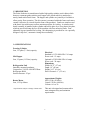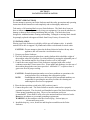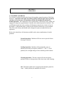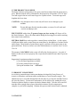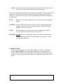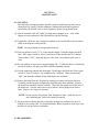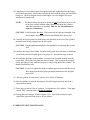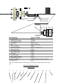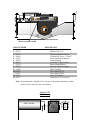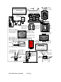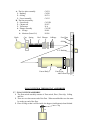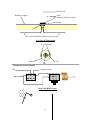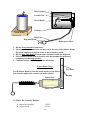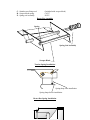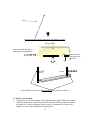
1
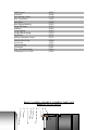
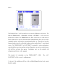
SERVICE MANUAL MODEL 117W
FROSTY FACTORY OF AMERICA INC.
RUSTON, LA. 71270
(318) 255-1162
All technical data, pictures and drawings contained in this manual are not binding on the
manufacturer nor can the manufacturer be held liable for any modifications to the
machine in whole or in part.
Rev. 4/11/00 rf.
1
SECTION 1
INTRODUCTION
1.1 USE OF THIS MANUAL
Your service manual has been prepared as a guide to help you get the most from your
Petite Sorbeteer. It contains information about the installation and operation of your
machine. The manual also contains instructions for service and care. The manual should
be read carefully by the operator of the Petite Sorbeteer to become familiar with the
machine and the correct operating procedures described within. The following notations
are used throughout the manual to bring important facts to your attention:
“Warning” - This notation is used whenever the personal safety of the operator(s) might
be jeopardized, if procedures are not followed correctly.
“Caution” - This notation is used whenever the machine or related equipment may
receive or cause damage if not observed.
“Note” - This notation is used to bring important information to your attention that will
enhance the performance of your machine.
1.2 PRELIMINARY INSPECTION
Unpack the unit as soon as possible upon its arrival. Check the entire machine and its
contents for possible shipping damage. Note damage, if any, and notify your carrier
immediately. Frosty Factory of America cannot be responsible for damaged merchandise
caused by shipping. Inventory the accessories to be sure they include the items you
specified on your order. Normally the accessories include:
___
___
___
___
___
___
___
___
___
Beater Bar
Drip Tray
Faceplate
Faceplate Knobs
Hopper Cover
Petro-Gel
Sanitizer
Spare Faucet O-Rings
Water Hoses
Warranty Card
___ Wire Brush
2
1.3 DESCRIPTION
The Petite Sorbeteer is manufactured with a high quality stainless steel cabinet which
houses a restaurant grade stainless steel hopper and cylinder which is attached to a
sturdy, hand-crafted steel frame. The hopper and cylinder are joined by a feed hole to
allow gravity flow operation. The drive motor is mounted within the frame and rotates
counter clockwise (as viewed from the front of the machine). Panels are stainless steel
with plastic louvered inserts to allow maximum airflow for cooling. A stainless steel
beater assembly is installed in the cylinder and held in place by a clear plastic faceplate,
which in turn is held onto the face of the machine with four attractive knobs. Four
adjustable legs are installed for leveling. Mix dispensing is provided for via a specially
designed “drip-free”, automatic closing faucet assembly.
1.4 SPECIFICATIONS
Freezing Cylinder
One, 3.5 quart (3.3 liter) capacity.
Mix Hopper
One, 12 quart (11.5 liter) capacity.
Refrigeration Unit
Internally mounted condenser.
Compressor: 3/4 H.P. 6600 BTU/Hour
Refrigerant: R404
Suction Pressure: 25 psi
Beater Motor
One, 1/12 hp. Motor
* Specifications subject to change without notice
Electrical
Standard is 115V/60Hz/1Ph. 12.0 amps
Power cord - 15 amps
Optional is 230V/60Hz/1Ph. 6.0 amps
Power cord - 20 amps
Dimensions
Width: 10.75” (27 cm)
Depth: 19” (48 cm)
Height: 24.5” (62 cm)
Floor Clearance: 1” (2.5 cm)
Approximate Weights
Net: 112 lbs. (50 kilos)
Crated: 122 lbs. (60 kilos)
Volume: 6.0 cu. Ft.
This unit is designed and constructed to
meet stringent safety and sanitation
requirements.
3
SECTION 2
LOCATION & INSTALLATION
2.1 SAFETY PRECAUTIONS
Do not attempt to operate your Petite Sorbeteer until the safety precautions and operating
instructions in this manual are read completely and are thoroughly understood.
Take notice of all warning labels on your Petite Sorbeteer. The labels have been put
there to inform and protect persons servicing your equipment. Care must be taken not to
damage or destroy labels during installation and servicing. The labels have been
designed to withstand routine cleaning and handling. Damaged or missing labels should
be promptly replaced with approved labels from Frosty Factory of America Inc.
2.2 INSTALLATION
Placing your Petite Sorbeteer in a highly visible area will enhance sales. A suitable
station will be able to support 150 pounds and will have a dedicated electrical outlet.
CAUTION: Do not attempt to share the dedicated electrical outlet with any other
appliance, this will cause the circuit breaker to trip.
1. Uncrate your Petite Sorbeteer.
2. The Petite Sorbeteer must be placed on a sturdy platform able to hold the weight of
the machine when full of product. Level the machine by turning the adjustable part of
the leg. The machine must be level front to back as well as left to right.
3. Connect the water supply hoses. Petite Sorbeteers equipped with water-cooled
condensers must have correct water flow. Water intake and discharge is at the rear of
the machine through the water hoses provided. All Model 117’s require at least ¾
gpm water flow for proper cooling.
CAUTION: Extended operations under severe heat conditions or operations with
restricted water flow can damage the refrigeration system.
NOTE:
Establishments which serve beverages from frozen drink machines are
responsible for providing the necessary facilities for cleaning and
sanitizing their food service equipment.
4. Place the three-position switch in the OFF position (center).
5. Connect the power cord. The Petite Sorbeteer must be connected to a properly
grounded receptacle. The electrical cord furnished as part of the Petite Sorbeteer has
a three prong grounding type plug. The use of an extension cord is not
recommended. If one must be used, refer to the national and local electrical codes.
Do not use an adapter to get around grounding requirements.
WARNING; do not attempt to alter the electrical plug. Serious injury or
electrocution may result.
6. Install the drip tray, cover, beater bar and faceplate assemblies on the Petite
Sorbeteer.
4
SECTION 3
OPERATION
3.1 MACHINE CONTROLS
Two selector switches located on the front of the machine control operation of the Petite
Sorbeteer. Selection of the right (snowflake) position with the upper (three-position)
switch as well as the lower (two-position) switch will schedule the machine for
normal operation. The compressor cycle is protected by a time delay circuit, which will
engage the compressor approximately 2 minutes after normal operation is initiated. The
red fill light located above the switches will illuminate when the level of mix is low in
the hopper. A thermostat knob is visible on the electrical control box of your machine.
This is set at the factory and should not be changed except by an authorized service
repairman.
Refer to the chart below for functions available with various combinations of switch
positions.
Normal Operation - Machine will freeze mix to provide frozen
beverage as desired.
Cooling Operation - Machine will automatically come on
whenever necessary to keep mix cooled to 5º C/40º F - used
primarily for overnight storage of mix remaining in the machine.
Cleaning Operation - The drive motor will run in the faucet
position to allow a stirring action of the rinse water while cleaning.
Off - The hand symbol is the recognized international symbol for
“stop”. In this position, the machine will not run.
5
3.2 THE PRODUCT YOU SERVE
The Petite Sorbeteer will produce a fine grain, semi-frozen slush when the proper mix is
used. When measured with a refractometer, the proper mix will measure 12 to 18 “brix”.
Too little sugar in the mix will cause larger ice crystals to form. Too much sugar will
lengthen the freeze time.
CAUTION: Any attempt to freeze water only will cause severe damage to your
machine.
NOTE:
Do not add sugar directly into the machine, as some of it will settle and
result in an improper mix.
FRUIT JUICES with at least 32 grams of sugar per 8-oz. serving will freeze well in
the Petite Sorbeteer. They will remain stable during the freezing process while retaining
their natural color and flavor.
NEUTRAL BASES are used to produce a neutral frozen cocktail base. A wide variety
of different drinks can be created from one neutral base by the addition of various flavors
and/or liquor. Most brands of neutral bases specify a mixture of four parts water to one
part neutral base. However, before use in the Petite Sorbeteer, be sure the “brix” level is
12 to 18.
The amount of ALCOHOL in the recipe will affect the freezing process. As a rule of
thumb, for the mix to freeze properly, the recipe should contain no more than 25 percent
alcohol.
Suggestion for optimum production and sales:
1) Use the finest ingredients available.
2) Test the product before serving it.
3) Keep the machine clean - ALWAYS!
3.3 PRODUCT CONSISTENCY
An exclusive patented torque sensing mechanism developed by Frosty Factory of
America will produce consistent texture and thickness of your frozen beverages. The
adjustment screw (accessible through the left side panel as you face the machine front) is
pre-set at the factory. Various mix consistencies can be achieved by turning the screw
clockwise (thicker drink) or counter clockwise (thinner drink). Turn the screw one full
turn then allow enough time to lapse (about three minutes) for the compressor to
complete a cycle before sampling. Continue this process until desired result is obtained.
3.4 START UP
6
NOTE: Before start-up, be sure the machine has been sanitized in accordance with
procedures set forth in the cleaning section of this manual.
Pour the mix into the hopper and allow it to drain into the cylinder. When the hopper and
cylinder are full (normally about one inch from the top of the hopper) the machine is
ready to run. Turn on by selecting the “right” (snowflake) position of both switches on
the front panel.
NOTE:
Add mix as soon as the red light comes on to prevent air from entering the
cylinder.
CAUTION: Allowing air into the cylinder will cause a gentle rocking motion of the
machine. If the mix is not yet frozen the air will escape by turning the
machine off for 20-30 seconds.
NOTE:
Pre-cooling the mix will reduce freeze-time, example: mix poured in
at 40º F will freeze in half the time of mix at 80º F.
WARNING: NEVER under any circumstances, place your finger or any other object
into the hopper or feed hole while the machine is in operation. Serious
personal injury may occur.
3.5 FREEZE TIME
The freeze time on the Model 117W is approximately 10 minutes. This figure is
based on ideal conditions with a starting mix temperature of approximately 40
degrees. The time will increase if the coolant to the condenser is insufficient or too
hot. Some recipes with high alcohol or high sugar content will naturally take a little
longer.
7
SECTION 4
MAINTENANCE
4.1 CLEANING
The following cleaning procedure should be used for initial start-up and on an as
needed basis to comply with the minimum cleaning and sanitizing frequencies
specified by the Federal, state or local regulatory agency having jurisdiction.
(1) Turn the machine to the off, “hand” position remove hopper cover. Look in the
hopper to locate and remove the float and float clip for cleaning.
(2) If applicable, drain mix into a sanitized container as per local health code procedures.
Store in an adequate cooling facility.
NOTE: Do not put hands or foreign matter into mix.
(3) Pour two gallons of cool (75ºF.) water into the hopper. Clean the hopper and feed
hole. Place upper switch in “faucet” position to let the machine stir for 2 minutes.
Turn machine “OFF”, drain and dispose of the rinse water. Repeat until water is
clear.
(4) Mix two gallons of warm water (approximately 100º F) with two ounces of sanitizing
powder to achieve 100 parts per million (PPM) sanitizing solution.
(5) Pour the sanitizing solution into the hopper. Clean hopper and feed hole. Place upper
switch in “faucet” position. Let solution stir for 5 minutes. Then, turn machine
“OFF” and drain the solution. Rinse with fresh water and drain.
(6) Remove the knobs from the faceplate by turning in a counter clockwise direction.
Carefully pull the faceplate straight away from the front of the machine. Remove
the beater bar assembly from the cylinder. Then slide the spring seal off the rear of
the beater bar. Unscrew white faucet cap to remove faucet plunger from faucet
body. Remove all o-rings for cleaning.
NOTE: Do not unscrew faucet body from faceplate to clean. (Leak free service
after disturbing the Teflon seal cannot be assured).
(7) All parts removed during the above steps plus the drip tray and insert can now be
cleaned in your warm (100º F) sanitized solution. Rinse all parts in clean rinse water
and allow to air-dry before re-assembly.
4.2 RE-ASSEMBLY
8
(1) Using Petro-Gel (or other sanitary food grade lubricant), lightly lubricate the longer
end of the beater shaft. Slide beater seal onto the shaft with the spring end toward the
beater bar. (Refer to diagram on top of the hopper cover for diagram of correct
installation of spring seal).
NOTE:
The black carbon ring must be facing the end of the beater bar so it will
be in direct contact with the white ceramic seal inside the cylinder
when the beater bar is re-installed. This is a dry seal and must be
kept free of lubricants.
CAUTION: Lube the beater bar shaft. The beater seal may become damaged if the
beater shaft is not lubricated before installation of the beater seal.
(2) Carefully insert the beater bar (with beater seal) into hole at the rear of the cylinder
and rotate until it fully engages into the drive plate.
CAUTION: Rough handling during beater bar installation can damage the ceramic
seal.
(3) Lubricate the large, black, rubber, faceplate O-ring with Petro-Gel then re-install and
press firmly into the faceplate groove for proper fit. Re-install o-rings on faucet
(4) Re-install the faceplate on the machine. First place the faceplate bushing onto the
beater shaft. Then slide face plate onto the four studs. Now re-attach the faceplate
knobs and tighten evenly until the faceplate O-ring is snug against the cylinder. Reinstall float and float clip.
CAUTION: If you over tighten the knobs or tighten against a beater bar that is not
fully engaged in the drive plate permanent distortion to the faceplate
may occur!
(5) Mix two gallons of warm water with one 2 oz. Packet of Sanitizer.
(6) Pour two gallons of solution into hopper. Clean the hopper and feed hole with a
clean sanitized brush.
(7) Place upper switch in “faucet” position. Let solution stir for 5 minutes. Turn upper
switch “OFF” (hand position). Drain all solution.
(8) Pour product into hopper. Replace hopper cover. Place both switches in right
(snowflake) position when ready to freeze product.
4.3 PREVENTATIVE MAINTENANCE
9
It is recommended that a maintenance schedule be followed to keep the machine clean
and operating properly.
WARNING; never attempt to repair or perform maintenance on machine until the
main electrical power has been disconnected.
A. DAILY
The exterior of the machine should be kept clean at all times to preserve the luster
and sanitation of the stainless steel. A mild alkaline cleaner is recommended. Use a
soft cloth or sponge to apply the cleaner.
B. WEEKLY
(1) Check O-rings and rear seal for excessive wear and replace if necessary.
(2) Clean the drip tray and front of the cabinet with a mild soap solution.
C. MONTHLY
(1) Check the water inlet hoses to be sure that they not crimped or folded which would
restrict the water flow to the unit.
(2) Remove water hoses from rear of machine and inspect inside the water fittings for
sludge build-up. If necessary sludge can be removed with a small wire brush.
4.4 EXTENDED STORAGE
Refer to the following steps for storage of the machine over any long period of shutdown
time:
(1) Turn the three position switch to the OFF (center) position.
(2) Disconnect (unplug) from the electrical supply source.
(3) Clean thoroughly with a warm detergent all parts that come in contact with the mix.
Rinse in clean water and dry all parts. Do not sanitize. Petite Sorbeteer parts can be
left disassembled until ready for use.
NOTE: Do not let the cleaning solution stand in the hopper or in the cylinder
during the shutdown period.
4.5 TROUBLESHOOTING
1. Machine does not run when turned on.___________________________________
A. Be sure that the plug is properly installed in wall outlet.
B. Check and reset circuit breaker if necessary.
C. Be sure that no other appliances are sharing the circuit.
10
D. If problem remains, call service repairman.
2. Beater motor starts but compressor doesn’t._______________________________
A. Both switches must be in the right (Snowflake) position.
B. Allow approximately one or two minutes for time delay to respond.
C. Check that the machine has been properly leveled.
D. If problem causes circuit breaker to trip, call service repairman.
3._ Mix dripping from drip tube.___________________________________________
A. Spring seal on beater bar is dirty or improperly installed. Remove, clean and reinstall spring seal assembly according to instructions and diagram on top of the
hopper cover.
B. Ceramic seal (inside the freezing cylinder) is dirty or loose. Clean ceramic seal.
If loose re-install as necessary. Also check that the carbon ring on the seal is not
chipped, cracked, dirty or greasy. Replace seal if necessary.
4. Unit runs but product does not freeze to desired consistency.________________
A. Check recipe for proper amount of sugar.
B. Check tension of TCC screw, if necessary turn clockwise to increase thickness of
drink.
C. Check unit for adequate water flow. (At least ¾ gal per minute is required on all
Model 117 water-cooled units.)
D. Check the water condenser to see if the pipes have become clogged with sludge,
and that the water hoses are not crimped. Remove sludge with wire brush.
E. Be sure that the water supply faucets are opened properly.
F. If problem remains, call service repairman.
5. Fill light is on when hopper is full of product._____________________________
A. Remove and re-install float with two dots facing up.
B. If float is stuck, clean float and stem and re-assemble.
6. No product comes out when faucet handle is pulled while unit is running.______
A. Frozen product is blocking “feed hole”. Turn machine off then clear ice plug
from feed hole.
WARNING: Never place fingers in the “feed hole” as serious personal injury
may occur.
B. Mix is frozen solid. Low sugar content, product separation or cylinder not full of
product.
7. Compressor starts and stops
intermittently.________________________________
A. If water-cooled check to see that the water is turned on and flowing freely.
B. If the on/off time is 30 seconds or longer, this is normal if product is frozen and
no product has been pulled in a while.
C. If the problem is causing the breaker to trip, call service repairman.
8. Unit continues to run when switched to stand-by___________________________
A. Have qualified technician remove back panel and reset thermostat. (Turn all the
way off then turn all the way on again.)
B. If problem remains call service repairman.
9. Beater bar does not turn_______________________________________________
11
A. Mix is frozen solid. See item 6-B.
B. Drive coupling stripped. Call service repairman.
C. Faulty motor. Call service repairman.
10. Thermostat does not respond when different knob positions are selected.______
A. If both switches are selected to “Snowflake”, the thermostat will not function.
B. Place the upper switch in the “Snowflake” position and the lower switch in the
“Thermometer” position. If mix is frozen the machine will stop running. If
machine continues to run the thermostat must be re-set.
C. To re-set thermostat, turn the thermostat knob all the way off and all the way back
on again. (Position 7 on the indicator).
D. The thermometer only works in the “Stand-by” position.
SPARE PARTS LIST
PETITE SORBETEER MODEL NO. 117W
DESCRIPTION
ITEM NUMBER
¾ H.P. Compressor 115/60/1
Start Relay
Start Capacitor
AKA9455ZXA-115/60
820ARR3D10
85S250C30
12
Run Capacitor
¾ H.P. Compressor 230/60/1
Start Relay
Start Capacitor
Run Capacitor
Bearing Spacer Block
Beater Bar
Beater Bar Spring Seal
Bottom, 2-Position Switch
C-Bracket
C-Bracket Stub
Contactor
Drip Tray
Drip Tray Screws
Drip Tube Brush
Drive Coupling
Drive Motor 115V
Drive Motor 230V
Drive Motor Start Capacitor 115V
Drive Motor Start Capacitor 230V
Face Plate
Face Plate Bushing
Face Plate Knob
Face Plate O-Ring
Faucet Assembly
Faucet Body
Faucet Brush
Faucet Nut
Faucet O-Ring
Faucet Plunger Assembly
Faucet Spring
Fill Light
Fill Light Switch
Fill Switch O-Ring
Filter-Dryer
Float Clip
Front Cross Brace
Front Motor Bearing
Heat Sequencer
85PR370F20
AKA9455ZXD-230/60
820ARR3C29
85685
85PR37036
C2316B
C6518
F0355
F0417
F1206
C1207
F0478
F6602
F0905
F6526
C0906
F0409
F0415
F0430
F1108
C6521
C6520
F0264
F0357
C6513
C6513B
F0326
F0197
F0491
C6513P
F0564
F0207
F0811
F0161
F5595
F0812
F1219
F0474
F0400
ITEM NUMBER
DESCRIPTION
High Pressure Switch
Hopper Cover
Left Side Panel
Mercury Switch
Motor Adjustment Bracket
Motor Spring Bracket
F0660
F0498
F6436
F0209
F1225
F1239
13
Panel Louver
Petro-Gel
Rear Bearing Carrier
Rear Cross Brace
Rear Panel
Rear Support Bearing
Right Side Panel
Sanitizer
Scraper Blade
Scraper Blade Spring
Sign Panel
Spring Adjustment Carrier
Stainless Steel Legs
Switch Nut
Tension Spring
Thermostat
Top, 3-Position Switch
Transformer-115V/230V
F0254
F0298
C1216
F1221
F6438
F0479
F6437
F0492
F6510
C6517
F0171
F0432
F0800
F7003
F0432
F0401
F0416
F4995
REAR CYLINDER AND DRIVE ASSEMBLY PARTS LIST
Models 113, 117, 217, 513, 527
1
2
3
4
5
6
7
8
9
14
blk to dk blu w/ wire nut
red to sw 1
lt blu to run cap.
wht to run cap.
gry to run cap.
10
11
12
13
14
15
DESCRIPTION
PART NUMBER_____________________
1. Ceramic Seal*
F0355*
2. Bearing Spacer Block
C2316B
3. Front Motor Bearing
F0474
4. Flat Washer
F0443 (5/16”)
5. Nut
F0439 (5/16”x18)
6. Drive Coupling
C0906
7. Stop Bolt Assembly
F0435 (¼”20x11/4”)
8. Mercury Switch
F0209
9. Drive Motor 115V
F0409
Drive Motor 230V
F0415
10. C-Bracket
F1206
11. C-Bracket Stub
C1207
12. Rear Support Bearing
F0479
13. Rear Bearing Carrier
C1216
14. Rear Cross Brace
F1221 (F5578 for models 217&527)
15. Frame Screw
F0237
*F0355 is the part number for the Spring Seal Assembly, which includes the ceramic
seal.
Torque Consistency Control
Model 117W
1
2
3
4
5
6
7
15
8
9
10
11
12
Wires to control circuit
ITEM NUMBER
DESCRIPTION
1. F0443
2. F1238
3. F0440
4. F1225
5. F0432
6. F0438
7. F1239
8. F0209
9. C0906
10. F0409
-- F0415
11. F1219
12. F0237
Washer, Flat 5/16”
Spring Adjustment Carrier
Tension Adj. Screw ¼”x20x3”
Motor Adjustment Bracket
Tension Spring
Lock Nut ¼”x20 (2 each)
Motor Spring Bracket
Mercury Switch Assembly
Drive Coupling
Drive Motor(115V)
Drive Motor(230V)
Front Cross Brace
Frame Screw (5/16x18x1/2)
Note: Items numbered 9 through 12 are not part of the torque consistency control
system, but are listed for user convenience.
Model 117W
Wire Drawing
Start Capacitor
4
5
Start
Relay
16
L2
L1
txr
1
Run Capacitor
2
brn from
merc. switch
brn from merc. switch
blu from HP switch
Gray
Purple
T-stat
Contactor
T block
txr
wht to relay #4
blk fr. Sw
blu fr Sw
wht fr L2 T-blk
blk fr capacitor
red fr Comp.
4
5
Comp.
Relay
1
2
blk fr run cap.
blu to brn @ sw. then to txr
blu to wht @ sw. then to ht. seq
Mercury Switch
brn-ht. seq.-top
L2
L1
txr
blk fr cont.
blk fr Comp.
wht fr Comp.
blk fr st. cap.
wht fr txr
blk to cont.
blk fr txr.
Fill Light
Heater
HP Switch
wht to txr &
ht sequencer
Contactor
Top view
blk jumper to
blk to L1
relay #5
brn to ht seq.
Motor wires
red to red from switch
brn-ht.seq.-bottom
gry & wht to capacitor
blu to capacitor
brn-contactor
blk-T-blk-L1
wht 24v to ht seq
blu-T-blk-txr
prp-t-stat
To Start Relay
brn 24v to sw(hp)
red-to.dr.mtr
gry-t-stat
blk to #5
blk to t-block TR
wht to ht seq
red to #4
wht to L2
wht to#2
Comp.
Cord
txr
Face Plate/Faucet Assembly
Face Plate/Faucet Assembly
HP
switch
Part No.
17
A. The face plate assembly
1. Bushing
2. O-Ring
3. Faucet assembly
B. The faucet assembly.
1. Faucet body.
2. Chrome nut
3. Teflon tape.
4. Plunger assembly
a. O-rings
b. lubricate (Petro-Gel)
Knob
Cap
Spring
C6521
C6520
F0374
C6513
C6513B
F0197
N/A
C6513P
F0491
F0298
Rod
Plunger
O-Rings
Face Plate
O-Ring
F.P. Bushing
Faucet Body
Faucet Nut
Add Teflon Tape
FLOAT SWITCH & THERMOSTAT ASSEMBLIES
2.7 FLOAT SWITCH ASSEMBLY
1. The float switch assembly consists of: Post switch, Float , Float clip, O-Ring
and Nut.
2. There are two dots on one end of the float. When assembled the two dots must
be on the top end of the float.
3. Place O Ring so that it will be inside the hopper (sink bottom) when finished.
Clip
18
Post Switch
Bottom of hopper
Float
Hex shape for back-up wrench
O-Ring
Nut
Two wires from float switch to control circuit.
Top View of Float Switch
Two Dots(Up)
Float
Clip
Post
Thermostat System-Stand-By
L1
To upper Switch
2 pos. switch
T-Stat
Drip Tube Brush Usage
19
Drip Chamber
Ceramic Seal
Faucet Brush
Cylinder
Warm Water
Drip Tube
Drip tube Brush
Drain Spacer Block
1. Dip the Faucet Brush in warm water.
2. Insert brush into the hole in the ceramic seal in the rear of the cylinder. Rotate
the brush completely around to clean, as shown. Remove brush.
3. Dip the Drip Tube Brush in warm water and insert brush into drip tube.
4. Move brush back and forth to clean. Be sure the brush has been inserted
completely into the Drip chamber.
5. Clean the brushes with hot soapy water when done.
Faucet Brush Usage
Face Plate
Use the Faucet Brush to clean the inside surfaces of the faucet
as well as the inside of the ceramic seal in the cylinder.
Bushing
Faucet Body
Faucet Nut
2.2 Beater Bar Assembly-Daiquiri
A. Beater bar assembly..
B. Scraper blade.
C6518,
C6510
20
C. Stainless steel hinge rod
D. Scraper blade spring.
E. Spring seal assembly.
(Included with scraper blade)
C6517
F0355
Beater Bar Assembly
Spring
Spring Seal Assembly
Scraper Blade
Tension Spring Installation
Spring shape after installation
Spring shape before installation.
Beater Bar Spring Installation
21
Rod
Spring position is shown without scraper blade for clarity
Scraper Blade
Tap rod toward one side as
shown prior to installation.
Insert this end
into beater bar
hole first
After installation tap rod until evenly spaced in beater bar as shown.
2.3 Beater Seal Assembly
1. Using Petro-Gel (or other sanitary food grade lubricant), lightly lubricate the longer
end of the beater shaft. Slide beater seal onto the shaft with the spring end toward
the beater bar. (Refer to diagram in this section of your manual or on top of the
hopper cover for correct installation of spring seal).
22
2.
3.
The black carbon ring must be facing the end of the beater bar so it will be in direct
contact with the white ceramic seal inside the cylinder when the beater bar is reinstalled. This is a dry seal and must be kept free of lubricants. Lube the beater
bar shaft ONLY!
The beater seal may become damaged if the beater shaft is not lubricated before
installation of the beater seal.
BEATER-BAR SEAL INSTALLATION
Rear wall of cylinder
Carbon seal face
(must be grease free)
Ceramic seal inside cylinder
(must be grease free)
Rubber seal
Spring
Spring cup
Apply light film of grease
before assembly
Beater bar shaft
Beater seal assembled
and installed
Beater bar
Ceramic Seal
Removal and replacement
Ceramic Seal
“T” Handle pulling tool
Grainger Part No. 1E 842
Spring loaded
23
ball bearings
Push button
To remove old seal;
1. Press the “Push button” to release ball bearings.
2. Insert “T” handle through ceramic seal at rear of cylinder.
3. Release “Push button”.
4. Quickly pull “T” handle straight out and the ceramic seal will remain on the “T:
handle as shown above.
Cylinder
ceramic
seal
Note: Do not hold button in while pulling “T” handle out.
To install new seal;
1. Apply silicone around rear, grooved surface, of ceramic seal (Do not allow silicone to
touch the smooth surface of the ceramic ring.)
2. Press seal into hole at rear of cylinder. Silicone coated surface goes in first.
3. Gently tap ceramic ring with wood or plastic rod until the seal has completely
bottomed out. (The handle of a standard hammer works well if used carefully)
4. The smooth surface of the ceramic seal must be completely clean in order to provide
proper sealing when the beater bar with spring seal is installed.
5. If possible allow at least four hours for silicone to cure before filling machine with
product. If four hours are not available, place hair dryer 2 feet away for about 30
minutes. (Do not use the hottest setting).
6. Fill machine with product and check for leaks.
7. Machine is ready to run.
Water Bracket Assembly
(Exploded View)
24
Fitting, Water Hose
F6100
Fitting, Bulkhead Water
F6101
Star Washer
Nut
Frame
Bracket, (Water/Refrigeration)
F0200
1.
2.
3.
4.
Insert the water bulkhead fitting P.N. F6101 through the bracket hole.
Place the star washer over the threaded portion of the bulkhead fitting.
Install the nut onto the threaded portion of the bulkhead fitting.
Apply thread tape to the water hose fitting P.N. F6100 and install into the
bulkhead fitting.
Note: Do not over-tighten the water hose fitting.
Wire Diagram
25