1
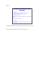
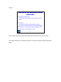
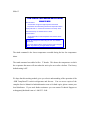
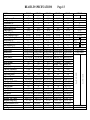
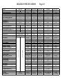
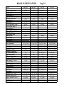
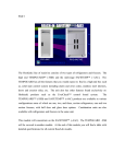
Slide 1 REACH- IN TEMPGUARD (-SSB) RH1-SSB-GD H O S H I Z A K I RFH2-SSB A M E R I C A The Hoshizaki line of reach- ins consists of two types of refrigerators and freezers. The high end TEMPGUARD (-SSB) and the mid-range SAFETEMP (–AAC) are the two product lines available. The TEMPGUARD has all the features that you would expect to find in a high-end box such as, solid state control system including alarm and error codes, completely stainless steel interiors, doors and exterior sides, etc. The unit also has other features found exclusively on Hoshizaki products such as the EverCheck™ control board system. The TEMPGUARD™ and SAFETEMP™ is available in various configurations some of which are one, two, and three section refrigerators, one and two section freezers, with half door and glass door options. Combination units are also available with refrigerators and freezers in the same unit. This module will concentrate on the TEMPGUARD (-SSB). The –AAC SAFETEMP will be covered in another module. At the end of this module you will find a table with detailed specifications for all current Reach-In models. Slide 2 -SSB REFRIGERATOR SEQUENCE H O S H I Z A K I A M E R I C A Refrigerator normal operation: When the power switch is turned “ON”, the control board starts the delay timer count. 2.0 minutes later the compressor, condenser fan motor, and evaporator fan motor start. The evaporator fan circulates air across the coil, through the stainless air duct, and to the cabinet. The cabinet is cooled until the desired set-point temperature is reached. The average pull-down time for an empty box to the factory set point is 21~23 minutes. This pull-down time would obviously vary when product is included in the cabinet. When the set point is reached, the cabinet temperature thermistor (K4) signals the board to stop refrigeration. This signal is simply a change of resistance that causes the control board program to react accordingly. The compressor, condenser fan motor, and the evaporator fan motor stop. K4 will signal the control board to cycle the compressor, condenser fan motor, and evaporator fan motor on and off as needed, to maintain the desired cabinet set point temperature. There is always a 2.0 minute restart delay for the refrigeration components. Defrost control: The defrost is temperature initiated and temperature terminated. Defrost will initiate by temperature through the defrost thermistor (K3). This thermistor is located in the fins of the evaporator coil evaporator. If the coil temperature gets below 13ºF the unit will go into an off cycle defrost which consist of de–energizing the compressor and condenser fan motor. The evaporator fan will continue to run. When the evaporator temperature has reached 40ºF the unit will cycle the compressor and condenser fan motor on and continue normal cycling. Slide 3 -SSB FREEZER SEQUENCE Freezer Normal Operation: When the power switch is turned “ON”, the control board starts the delay timer count. 2.5 minutes later the compressor, condenser fan motor, and evaporator fan motor start. The evaporator fan circulates air across the coil, through the stainless air duct, and to the cabinet. The cabinet is cooled until the desired set-point temperature is reached. The average pull-down time for an empty box to the factory set point is 21~23 minutes. This pull-down time would obviously vary when product is included in the cabinet. When the set point is reached, the cabinet temperature thermistor (K4) signals the board to stop refrigeration. This signal is simply a change of resistance that causes the control board program to react accordingly. The compressor, condenser fan motor, and the evaporator fan motor stop. K4 will signal the control board to cycle the compressor, condenser fan motor, and evaporator fan motor on and off as needed to maintain the desired cabinet set point temperature. There is always a 2.5 minute restart delay for the refrigeration components. Defrost: The defrost system for all freezer models uses electric heater strips and is time initiated and temperature terminated through the control board. Freezer defrost can be set to occur 1, 2, 3, 4, 6, or 8 times a day using the Guarded Access Menu. The factory setting is 6 per day. This means an electric defrost will occur every 4 hours from when the freezer is started. The number of defrost needed per day will vary depending on how each customer uses the reach-in. The number of defrost can be adjusted depending on freezer use. You may find that more defrost are required if the reach-in is opened frequently or operated in a humid environment. When a defrost occurs, “dEF” is displayed. Dur ing defrost, the evaporator fan motor, condenser fan motor, and compressor shut down and the electric heaters are energized. The heaters warm the evaporator coil to remove any ice build up. The defrost control thermistor (K3) terminates defrost once the center of the evaporator coil reaches 100°F. This should indicate a clear evaporator coil. Remember that this 100°F is coil temperature and is not circulated throughout the cabinet. When the coil temperature reaches 100°F at K3, the control board de-energizes the defrost heaters and starts a 5 minute delay timer. After 5 minutes, the compressor and condenser fan motor restart and the evaporator coil begins to cool. Once the evaporator temperature reaches 0°F, K3 signals the board to restart the evaporator fan motor. When the temperature reaches within 15°F of the cabinet temperature set-point, the display changes from “dEF” to the cabinet temperature. The “dEF” display is maintained till the cabinet cools so that the customer will not be alarmed at a slightly higher than normal cabinet temperature. The electric defrost system is backed up by two additional safeties. A one hour maximum defrost timer starts counting when the defrost begins. If the coil temperature fails to reach 100°F within one hour, this timer will terminate defrost and cause an E3 defrost alarm sounding 5 beeps every 10 seconds. A bi-metal switch also backs up the defrost system. This switch is mounted on the top of the evaporator coil. If the temperature at the top of the evaporator coil reaches 120°F, this switch opens to signal the board to shut down the electric heaters. The control board will continue in defrost with no electric heaters until the one hour timer causes an E3 alarm. Pressing the reset at the display panel will clear the E3 alarm. If 4 consecutive E3 alarms occur pressing the reset at the display will only silence the beeper. The E3 code will not clear until a service technician presses the master reset on the control board. Obviously, the defrost system should be checked for a problem in this case. Slide 4 -SSB CONTROL CIRCUIT -SSB CONTROL BOARD RIBBON CABLE DISPLAY BOARD H O S H I Z A K I A M E R I C A The –SSB uses an EverCheck™ control system that incorporates a control board, ribbon cable and display board. This system controls the unit operation and provides error alarms and diagnostic information to inform the customer of a potential problem before damage to the product occurs. The same control board is used in either a Refrigerator or Freezer. DIP switches are set each application. This provides a universal replacement control for the –SSB product line. Follow the instructions provided with the replacement board to set the DIP switches for your application. Slide 5 -SSB SERIES CONTROLLER ADJUSTMENT GUARDED ACCESS MENU •Accessing: •Press the “UP” and “DOWN” keys together for three seconds. Press both buttons at the same time H O S H I Z A K I A M E R I C A There are two menus incorporated in the –SSB, the Guarded Access menu and the Diagnostic Menu. These menus allow you to make adjustments in the operation of the unit as well as check diagnostic information when trouble shooting the reach- in. By pressing the “UP” and “DOWN arrow keys at the same time for 3 seconds you can gain access to the Guarded Access Menu. Slide 6 -SSB SERIES CONTROLLER ADJUSTMENT GUARDED ACCESS MENU •1st Adjustment: •Temperature Setpoint Average cabinet temperature •2nd Adjustment: •Defrost Frequency Refrigerator: Automatic defrost “df X” has no effect Freezer: Ex. “df” 4 = 4 defrost per day •3rd Adjustment: •Units of display: F = Fahrenheit C = Celsius You can make three adjustments once you have accessed the Guarded Access Menu. To navigate to the next step press the “ENTER” button. The first item that can be adjusted is the set point of the reach- in. This is the temperature that the unit will maintain. Factory default for the freezer is -3ºF and the refrigerator is 36ºF The second item is the defrost frequency. This is the number of defrost per day and only applies to freezers. If can be adjusted for 1,2,3,4,6,8 defrost however. However the factory default adjustment is 6 per day The third and final item that can be changed from this menu is the temperature scale that the display reads. Either F = Fahrenheit or C = Celsius . To make adjustments in any of these steps use the “UP” and “DOWN” arrow keys. You must cycle through the entire menu, back to the temperature readout by pressing enter, before the changes will take affect. Slide 7 TEMPGUARD™ (-SSB) DISPLAY CODES • Alarm display~ Alternates between code and box temp. • E1- High Cabinet temperature ~ 3 Beeps 25° F above set point for more than 4 hours • E2- Low cabinet temperature ~ 4 Beeps 8° F Below set point for more than 1 hour • E3- Freezer defrost over 1 hour ~ 5 Beeps • E4- High pressure 3 x in 1 hour ~ 6 Beeps (5 x cuts off) • E6 - E7 High voltage (8 Beeps) and Low voltage (9 Beeps) • E8 - E9 Defrost or Cabinet temperature sensor failure (Continuous buzzer) • E10 Communication error (Dual Temp only) • dEF Unit in defrost or recovery • CF~ Clean filter ~ 1 Beep. • door~ Displays when open~ 2 Beeps if open>3 Min TEMPGUARD (-SSB) ALARM CODES There are several audible alarms and visual codes which may be displayed to alert the customer of potential problems before product is damaged. The display will alternate between the alarm code and box temp. Below you will find a brief explanation of each error. Also a label on the control box provides general information about these alarms and codes. CF ~ Clean filter ~1 Beep This alarm will be shown when the air filter has become clogged. There is a bi- metal (Klixon) switch on the discharge line that will send a signal to the board when the discharge line temp begins to rise. After cleaning the filter, allow time for the sensor to reset, then press “RESET” on the display board to reset the alarm. “door” Displays when the door is open When the door is open the display will read “door”, to alert the customer that the door may be ajar. If the door remains open for more than 3 minutes the unit will beep 2 times. This alarm will reset once the door is closed. E1- High cabinet temperature ~ 3 Beeps If the unit experiences a temperature of 25°F above set point for more than 4 hours the unit will sound a 3 beep alarm and display “E1” alternating with the box temperature. E2– Low cabinet temperature ~ 4 Beeps If the unit experiences a temperature of 8°F below the set point for more than 1 hour the unit will sound a 4-beep alarm and show “E2” on the display. E3- Freezer defrost over 1 hour ~ 5 Beeps The unit will show an “E3” and a five-beep alarm if the unit stays in defrost for more than one hour. This alarm will only be seen on freezer units. E4- High pressure 3 x in 1 hour ~ 6 Beeps (5 x cuts off) The unit will begin to signal “E4” if the unit has tripped on high pressure 3 times within a 1-hour period. If the unit cycles off 5 times in a 1- hour period the unit will shut down in order to protect the refrigeration components. E6-E7 Voltage errors E6 High voltage safety. E7 Low voltage safety. Both of these alarms will automatically reset when the correct power is restored. E8-E9 Thermistor alarms E8 Cabinet Thermistor failure. E9 Defrost Thermistor failure. The unit will continue to operate using factory default operation. E10 Communication error Only applies to dual temperature units and results when the cable connecting the two control boards is either shorted or open. Slide 8 -SSB SERIES CONTROLLER ADJUSTMENT DIAGNOSTIC MENU •Accessing: •Press the “UP”, “DOWN” and the “ENTER” keys together for three seconds. Press all three buttons at the same time H O S H I Z A K I A M E R I C A To assist in trouble shooting the –SSB series a Diagnostic Menu is provided. This menu gives you the ability to send the unit into a manual defrost, change display sensors, clear all error codes as well as provide you with detailed information regarding the past operation of the unit. To gain access to this menu press the “UP”, “DOWN” and “ENTER” together for three seconds. To make adjustments in any of these steps use the “UP” and “DOWN” arrow keys. You must cycle through the entire menu back to the temperature display by pressing the “ENTER” key before the changes will take affect. Slide 9 -SSB SERIES CONTROLLER ADJUSTMENT DIAGNOSTIC MENU •1st Command: •1OFF Display shows Cabinet temperature •1ON Display shows Evaporator temperature Display automatically reverts back to cabinet temperature after five minutes. •2nd Command: (Freezer only) •2OFF Manual defrost initiation option is not activated •2ON Manual defrost initiation option is activated Will begin defrost once complete menu has been cycled through Does not change scheduled defrost time The first command will be shown as “1OFF” when the display is using the cabinet thermistor to read temperature (Normal). If this step is changed to “1ON” the display will read the actual evaporator temperature using the defrost thermistor. The reading will automatically revert back to the cabinet temperature after five minutes. This feature can be used to check the coil temperature for five minutes intervals at any time during the cycle including defrost. The second command is used only in freezer applications. When changed to “2ON” the unit will begin a manual defrost once the menu is cycled back to the temperature display. Slide 10 -SSB SERIES CONTROLLER ADJUSTMENT DIAGNOSTIC MENU •3rd Command: •3OFF Unconditional alarm reset option not activated •3ON Unconditional alarm reset option activated Resets all alarm display codes. Complete alarm reset •4th Command: •4 16 Number in right two digits represent Compressor run time in the last 24 hours (Example: 16 hours total run time in the last 24 hours) H O S H I Z A K I A M E R I C A The third command in the Guarded Access Menu is used for unconditional alarm reset. This is done by changing to “3ON” The fourth command will show the compressor run time in the last 24 hours. Slide 11 -SSB SERIES CONTROLLER ADJUSTMENT DIAGNOSTIC MENU •5th Command: •5 50 Number in right two digits represent percent of Compressor run time for the last 5 cycles. A cycle is from “off” to “on” Does not use cycle terminated by a defrost or the first cycle after a defrost. Value is saved every 5 cycles •6th command: •6 45 Number in right two digits is Compressor run time for the last run cycle. The fifth command will show the percentage of run time in the last five cycles. The sixth, command compressor run time for the last run cycle. Slide 12 -SSB SERIES CONTROLLER ADJUSTMENT DIAGNOSTIC MENU •7th Command: (Freezer Only) •7 45 Number in right two digits represent length of the last defrost. •8th Command: •8 67 Number in right two digits represent the highest temperature recorded during the last high temperature alarm Display will read “8--” if there has not been a high temp. alarm Value saved every 8.5 minutes when in alarm H O S H I Z A K I A M E R I C A The seventh command will show the length of the last defrost cycle (Freezer Only) The eighth command is the highest temperature recorded during the last high temperature alarm. Slide 13 -SSB SERIES CONTROLLER ADJUSTMENT •9th Command: DIAGNOSTIC MENU •9-10 Number in right two digits represent the lowest temperature recorded during the last low temperature alarm Display will read “9--” if there has not been a low temp. alarm Value saved every 8.5 minutes when in alarm 10th Command •0~25 Temperature of the evaporator when the fan will be energized. • Note: All changes are made using the “UP” and “DOWN” arrow keys. • You must advance all the way through the menu using the “Enter” key before any changes will be accepted. The ninth command is the lowest temperature recorded during the last low temperature alarm. The tenth command was added to Rev. 17 boards. This shows the temperature at which the evaporator fan motor will start when the unit cycles on or after a defrost. The factory default setting is 0°F We hope that this training module gives you a basic understanding of the operation of the –SSB TempGuard™ reach- in refrigerators and freezers. You can access copies of the complete Service Manual at hoshizakiamerica.com or for hard copies, please contact your local distributor. If you need further assistance you can contact Technical Support at [email protected] or 1-800-233-1940. RH1-SSB Refrigerator 115/60/1 7.0 15 7 1000 104-126 45-100 Electronic 36 to 50 36 +/- 3 22.3 16.1 22 gauge Stainless 22 gauge Stainless 22 gauge Stainless Off Cycle 13°F Coil Temp 40°F Coil Temp N/A N/A 2.5 min. 2.5 min. ON Temp Tecumseh AE9415EZXA 435 / 1490 4.5 / 29 5.05 1.83 10 fl. oz. 243-292 mfd@110V N/A R-404A / TXV 12.2 / 345g HP Control Full/Half UL/cUL/NSF RH2-SSB Refrigerator 115/60/1 10.0 15 11.7 1665 104-126 45-100 Electronic 36 to 50 36 +/- 3 48.5 35.3 22 gauge Stainless 22 gauge Stainless 22 gauge Stainless Off Cycle 13°F Coil Temp 40°F Coil Temp N/A N/A 2.5 min. 2.5 min. ON Temp Tecumseh AKA9427ZXA 790 / 2700 7.8 / 48 4.6 0.66 17 fl. oz. 161-193 mfd@165V N/A R-404A / TXV 18.2 / 515 HP Control Full/Half UL/cUL/NSF RH3-SSB Refrigerator 115/60/1 10.2 15 14.2 2020 104-126 45-100 Electronic 36 to 50 36 +/- 3 74.7 54.0 22 gauge Stainless 22 gauge Stainless 22 gauge Stainless Off Cycle 13°F Coil Temp 40°F Coil Temp N/A N/A 2.5 min. 2.5 min. ON Temp Copeland JS35C1E-CAA-252 1035 / 3530 9.2 / 46 9.58 0.88 20 fl. oz. 43-52 mfd@220V 15 mfd@440V R-404A / TXV 21.9 / 620 HP Control Full/Half UL/cUL/NSF FH1-SSB Freezer 115/60/1 8.6 15 13.0 1850 104-126 45-100 Electronic -10 to 25 -3 +/- 3 22.3 16.1 22 gauge Stainless 22 gauge Stainless 22 gauge Stainless Electric Heat Time 6/day (Adj.) 100°F Coil Temp 60 minutes Bi-metal / 120°F 2.5 min. 5 min OFF until 0°F coil * dEF Tecumseh AJA2425ZXA 720 / 2450 7.9 / 68 3.06 0.48 26 fl. oz. 270-324 mfd@165V 15 mfd@370V R-404A / TXV 16.6 oz. / 470g. HP Control Full/Half UL/cUL/NSF FH2-SSB RFH2-SSB Freezer Refrigerator Freezer 115/60/1 115/60/1 11.5 14.3 30 20 17.6 22.1 2500 3140 104-126 104-126 45-100 45-100 Electronic Electronic -10 to 25 36 to 50 -10 to 25 -3 +/- 3 36 +/- 3 -3 +/- 3 48.5 22.3 22.3 35.3 16.1 16.1 22 gauge Stainless 22 gauge Stainless 22 gauge Stainless 22 gauge Stainless 22 gauge Stainless 22 gauge Stainless Electric Heat Time 6/day (Adj.) 100°F Coil Temp 60 minutes Bi-metal / 120°F 2.5 min. 5 min OFF until 0°F coil * dEF Copeland RS80C1E-CAA 2390 / 3730 18.6 / 72.5 5.013 ~ 5.767 0.38 ~ 0.438 24 fl. oz. 88-106 mfd@330V 25 mfd@370V R-404A / TXV 21.5 oz. / 570g. HP Control Full/Half Full/Half UL/cUL/NSF UL/cUL/NSF See FH1-SSB MODEL Type Voltage/Frequency/Phase Running Amps (A) Circuit Breaker (A) Engy. Consump. (kWHr/Day) Heat Rejection (BTU/Hr) Voltage Range (V) Ambient Range (°F) Cabinet Temperature Control Control Setpoint Range (°F) Factory Setting (°F) Total Refrigerated Volume (ft^3) Total Shelf Space (ft^2) Exterior/Interior Finish Solid Door Liner Half Door Liner Defrost System Defrost Initiation Defrost Termination Defrost Maximum Defrost Safety Comp delay @ startup Comp delay @ end Defrost Fan operation during defrost Display during defrost Compressor Manufacturer Compressor Model Comp. Capacity W / BTUH Comp. RLA / LRA Comp. SWR ohms Comp. RWR ohms Comp. POE Oil Amount Start Capacitor Run Capacitor Refrigerant Type / Control Refrigerant Charge (ozs./g) Refg. Cir. Protection (auto reset) Door Types Agency Approvals Page 1/3 See RH1-SSB REACH-IN SPECIFCATIONS REACH-IN SPECIFCATIONS RFH3-SSB Refrigerator Freezer 115/60/1 16.3 30 21.1 3000 104-126 45-100 Electronic 36 to 50 -10 to 25 36 +/- 3 -3 +/- 3 48.5 22.3 16.1 35.3 22 gauge Stainless 22 gauge Stainless 22 gauge Stainless See FH1-SSB See RH2-SSB MODEL Type Voltage/Frequency/Phase Running Amps (A) Circuit Breaker (A) Engy. Consump. (kWHr/Day) Heat Rejection (BTU/Hr) Voltage Range (V) Ambient Range (°F) Cabinet Temperature Control Control Setpoint Range (°F) Factory Setting (°F) Total Refrigerated Volume (ft^3) Total Shelf Space (ft^2) Exterior/Interior Finish Solid Door Liner Half Door Liner Defrost System Defrost Initiation Defrost Termination Defrost Maximum Defrost Safety Comp delay @ startup Comp delay @ end Defrost Fan operation during defrost Display during defrost Compressor Manufacturer Compressor Model Comp. Capacity W / BTUH Comp. RLA / LRA Comp. SWR ohms Comp. RWR ohms Comp. POE Oil Amount Start Capacitor Run Capacitor Refrigerant Type / Control Refrigerant Charge (ozs./g) Refg. Cir. Protection (auto reset) Door Types Agency Approvals Full/Half UL/cUL/NSF Page 2/3 RH1-SSB-GD RH2-SSB-GD RH3-SSB GD PTR1SSB RH1-AAC Refrigerator Refrigerator Refrigerator Pass Through Refrigerator Refrigerator 115/60/1 115/60/1 115/60/1 115/60/1 115/60/1 9.4 12.7 15 12.0 6 15 20 20 15 15 13.9 25.5 29.1 16 6.4 1975 3620 4130 2273 910 104-126 104-126 104-126 104-126 104-126 45-100 45-100 45-100 45-100 45-100 Electronic Electronic Electronic Electronic Electronic 36-50 F 37 to 55 36 to 50 36 to 50 36 to 50 36° 39 36 +/- 3 36 +/- 3 36 +/- 3 22.3 48.5 74.7 23.8 22.3 16.1 16.1 16.1 35.3 54.0 22 gauge Stainless 22 gauge Stainless 22 gauge Stainless Stainless Stainless / Aluminum Glass Glass Glass N/A Stainless N/A N/A N/A Stainless & Glass Stainless Off Cycle Off Cycle Off Cycle Off Cycle Off Cycle 13°F Coil Temp 13°F Coil Temp 13°F Coil Temp 10 °F Coil Temp 13°F Coil Temp 40°F Coil Temp 40°F Coil Temp 40°F Coil Temp 40°F Coil Temp 40°F Coil Temp N/A N/A N/A N/A N/A N/A N/A N/A N/A N/A 2.5 min. 2.5 min. 2.5 min. 2.5 min. 2.0 min. 2.5 min. 2.5 min. 2.5 min. N/A 2.0 min. ON ON ON ON ON Temp. Temp Temp Temp Temp Tecumseh Tecumseh Copland Tecumseh Danfoss AKA9455ZXA RS64C1E-CAA NF7FX AKA9427ZXA AKA9427ZXA 1160 / 5450 1893 / 6460 500/1700 790 / 2700 790 / 2700 7.8 / 48 10. / 50 11 / 59 7.8 / 48 4 /28 4.6 5.95 5.282 ~ 6.078 4.6 6.6 0.69 0.533 ~ 0.613 1.9 0.66 0.66 17 fl. oz. 17 fl. oz. 24 fl. oz. 17 fl. oz. 10.8 fl. oz. 280 mfd@120V 161-193 mfd@165V 72-88 mfd@250V 72-86 mfd@330V 161-193 mfd@165V 30 mfd@440V N/A N/A N/A R-404A / TXV R-404A / TXV R-404a /TXV R-134a / Cap Tube R-404A / TXV 15.7 / 445 15.7 / 445 21.5 / 610 31.5 / 893 9.7 / 275 HP Control HP Control HP Control HP Control HP Control Full Glass Full Glass Full Glass Half Front and Rear Full/Half UL/cUL/NSF UL/cUL/NSF UL/cUL/NSF UL/cUL/NSF UL/cUL/NSF REACH-IN SPECIFCATIONS MODEL Type Voltage/Frequency/Phase Running Amps (A) Circuit Breaker (A) Engy. Consump. (kWHr/Day) Heat Rejection (BTU/Hr) Voltage Range (V) Ambient Range (°F) Cabinet Temperature Control Control Setpoint Range (°F) Factory Setting (°F) Total Refrigerated Volume (ft^3) Total Shelf Space (ft^2) Exterior/Interior Finish Solid Door Liner Half Door Liner Defrost System Defrost Initiation Defrost Termination Defrost Maximum Defrost Safety Comp delay @ startup Comp delay @ end Defrost Fan operation during defrost Display during defrost Compressor Manufacturer Compressor Model Comp. Capacity W / BTUH Comp. RLA / LRA Comp. SWR ohms Comp. RWR ohms Comp. POE Oil Amount Start Capacitor Run Capacitor Refrigerant Type / Control Refrigerant Charge (ozs./g) Refg. Cir. Protection (auto reset) Door Types Agency Approvals Page 3/3 RH2-AAC RH3-AAC FH1-AAC FH2-AAC Refrigerator Refrigerator Freezer Freezer 115/60/1 115/60/1 115/60/1 115/60/1 8.0 12.0 8.8 12.0 15 15 15 20 9.8 15.2 15 24 1390 2161 2158 3400 104-126 104-126 104-126 104-126 45-100 45-100 45-100 45-100 Electronic Electronic Electronic Electronic 37 to 55 37 to 55 -10 to 28 F -10 to 28 F 39 39 0 0 48.5 74.7 22.3 48.5 35.3 54 16.1 35.3 Stainless / Aluminum Stainless / Aluminum Stainless / Aluminum Stainless / Aluminum Stainless Stainless Stainless Stainless Stainless Stainless Stainless Stainless Off Cycle Off Cycle Electric Heat Electric Heat 13°F Coil Temp 13°F Coil Temp Time 6/day (Adj.) Time 6/day (Adj.) 40°F Coil Temp 40°F Coil Temp 100°F Coil Temp 100°F Coil Temp N/A N/A 60 Minutes 60 Minutes N/A N/A Bi-metal / 120°F Bi-metal / 120°F 2.0 min. 2.0 min. 5 min. after def. complete 5 min. after def. complete 2.0 min. 2.0 min. 5 min 5 min ON ON OFF until evap. 0°F OFF until evap. 0°F Temp. Temp. * dEF * dEF Danfoss Tecumseh Tecumseh Copeland NF11FX AKA4482YXA AJA2425ZXA RS80C2E-CAA-219 735/2500 1090 /8200 755 / 2450 1740 / 8170 5 / 28 12.3 / 59.0 7.9 / 68.0 18.6 / 72.5 3.6 1.0 10.8 fl. oz. 17.3 fl. oz. 26.0 fl. oz. 24.0 fl. Oz. 410 mfd@120V 64-77 mfd@250V 270-324 mfd@165V 88-106 mfd@330V N/A N/A 15 mfd@370V 25mfd@370V R-134a / Cap Tube R-134a / Cap Tube R-404a /TXV R-404a /TXV 11.6 / 330 20.6 / 585 16.6 / 470 20.1 / 570 HP Control HP Control HP Control HP Control Full/Half Full/Half Full/Half Full/Half UL/cUL/NSF UL/cUL/NSF UL/cUL/NSF UL/cUL/NSF


![Maximum Model service Manual.ppt [호환 모드]](http://vs1.manualzilla.com/store/data/006002079_1-f9e925e4876feffe85b493d91263fd66-150x150.png)