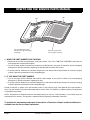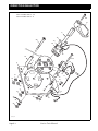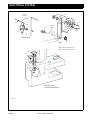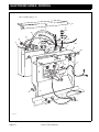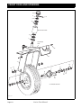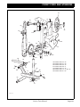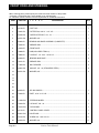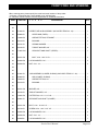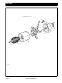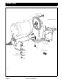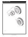
1
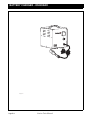
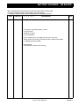
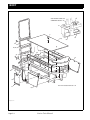
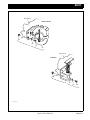
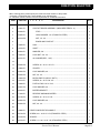
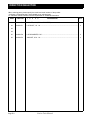
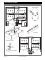
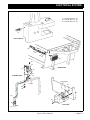
6055XX
ISSUED: JULY 2006
REVISED: SEPTEMBER 2009
SERVICE PARTS MANUAL
ELECTRIC THREE WHEEL
UTILITY VEHICLES
INDUSTRIAL 640
STARTING MODEL YEAR 2007
E-Z-GO Division of TEXTRON, Inc. reserves the right to make design changes without obligation to make these changes on units previously sold and the information contained in this manual is subject to change without notice.
E-Z-GO Division of TEXTRON, Inc. is not liable for errors in this manual or for incidental or consequential damages that result from the use of the material in this
manual.
CUSTOMER SERVICE DEPARTMENT IN USA PHONE: 1-800-241-5855 FAX: 1-800-448-8124
OUTSIDE USA PHONE: 001-706-798-4311, FAX: 001-706-771-4609
E-Z-GO DIVISION OF TEXTRON, INC., P.O.BOX 388, AUGUSTA, GEORGIA USA 30906-3852
Service Parts Manual
Page i
NOTES
To obtain a copy of the limited warranty applicable to the vehicle, call or write a local
Distributor, authorized Branch or the Warranty Department with vehicle serial number and
manufacturer code.
The use of non Original Equipment Manufacturer (OEM) parts may void the warranty.
Tampering with or adjusting the governor to permit vehicle to operate at above factory
specifications will void the vehicle warranty.
When servicing engines, all adjustments and replacement components must be per original
vehicle specifications in order to maintain the United States of America Federal and State
emission certification applicable at the time of manufacture.
BATTERY PROLONGED STORAGE
All batteries will self discharge over time. The rate of self discharge varies depending on the
ambient temperature and the age and condition of the batteries.
A fully charged battery will not freeze in winter temperatures unless the temperature falls
below -75° F (-60° C).
Page ii
Service Parts Manual
TABLE OF CONTENTS
SECTION
Page No.
HOW TO USE THE SERVICE PARTS MANUAL . . . . . . . . . . . . . . . . . . . . . . . . . . . . . . . . . . . . . . . . . . . . . vii
ILLUSTRATED PARTS BREAKDOWN . . . . . . . . . . . . . . . . . . . . . . . . . . . . . . . . . . . . . . . . . . . . . . . . . . . . . ix
ACCELERATOR . . . . . . . . . . . . . . . . . . . . . . . . . . . . . . . . . . . . . . . . . . . . . . . . . . . . . . . . . . . . . . . . . . . . . . A-1
BATTERY CHARGER - PORTABLE . . . . . . . . . . . . . . . . . . . . . . . . . . . . . . . . . . . . . . . . . . . . . . . . . . . . . . . B-1
BATTERY CHARGER - ON BOARD . . . . . . . . . . . . . . . . . . . . . . . . . . . . . . . . . . . . . . . . . . . . . . . . . . . . . . . B-3
BODY . . . . . . . . . . . . . . . . . . . . . . . . . . . . . . . . . . . . . . . . . . . . . . . . . . . . . . . . . . . . . . . . . . . . . . . . . . . . . . . C-1
BRAKES . . . . . . . . . . . . . . . . . . . . . . . . . . . . . . . . . . . . . . . . . . . . . . . . . . . . . . . . . . . . . . . . . . . . . . . . . . . . D-1
DIRECTION SELECTOR . . . . . . . . . . . . . . . . . . . . . . . . . . . . . . . . . . . . . . . . . . . . . . . . . . . . . . . . . . . . . . . . E-1
ELECTRICAL SYSTEM . . . . . . . . . . . . . . . . . . . . . . . . . . . . . . . . . . . . . . . . . . . . . . . . . . . . . . . . . . . . . . . . . F-1
ELECTRONIC SPEED CONTROL . . . . . . . . . . . . . . . . . . . . . . . . . . . . . . . . . . . . . . . . . . . . . . . . . . . . . . . G-1
FRONT FORK AND STEERING . . . . . . . . . . . . . . . . . . . . . . . . . . . . . . . . . . . . . . . . . . . . . . . . . . . . . . . . . . H-1
MOTOR . . . . . . . . . . . . . . . . . . . . . . . . . . . . . . . . . . . . . . . . . . . . . . . . . . . . . . . . . . . . . . . . . . . . . . . . . . . . . J-1
REAR AXLE . . . . . . . . . . . . . . . . . . . . . . . . . . . . . . . . . . . . . . . . . . . . . . . . . . . . . . . . . . . . . . . . . . . . . . . . . . K-1
WHEELS AND TIRES . . . . . . . . . . . . . . . . . . . . . . . . . . . . . . . . . . . . . . . . . . . . . . . . . . . . . . . . . . . . . . . . . . L-1
Service Parts Manual
Page iii
TABLE OF CONTENTS
Page iv
Service Parts Manual
HOW TO USE THE SERVICE PARTS MANUAL
This manual is divided into several sections:
GENERAL INFORMATION
• TABLE OF CONTENTS
• HOW TO USE THE SERVICE PARTS MANUAL
ILLUSTRATED PARTS BREAKDOWN
• Contains illustrations and parts lists for all systems of the vehicle
USE OF THE MANUAL
To use this manual, consult the TABLE OF CONTENTS (page iii) to locate the information or illustration required.
Introduction of some revisions varies due to supply of components; therefore, it is possible that various combinations of
components may be found that are not directly reflected by each illustration. Consult the illustration that best suits your
situation. Locate the serial number plate (see BODY located in the Illustrated Parts Breakdown section of this manual
for its location) and note the complete number shown on the plate. It is important that the serial number of your vehicle
and its model number be supplied to Service Parts when ordering any replacement components.
Service Parts Manual
Page v
HOW TO USE THE SERVICE PARTS MANUAL
Title
Title
106
*See Body Section for
decal information
102,104
Front of Vehicle
107
103
105
83,88
81,86
84,89
100
82,87
98
74
- 66, 69 Items 63
62 - IncludesItems 71 - 74
70 - IncludesItems 82 - 84
81 - IncludesItems 87 - 89
86 - IncludesItems 95, 96114
94 - Includes Items 112 -121
111 - IncludesItems 119 -131
118 - IncludesItems 127 126 - Includes
94
96
95
91
92
63
65
69
64
74
79
101
99
70
120
62
71
123
66
67
116
113
73
72
121
118
119
122
111
112
115
130
131
114
127
126
128 129
Left hand illustration page
(continued on right hand page
if required)
Parts list (continued on
rear of page if required)
1. WHEN THE PART NUMBER IS NOT KNOWN
• Determine the function and application of the part required. Turn to the TABLE OF CONTENTS and select the
most appropriate component description.
• Turn to the page number indicated and locate the part description in the parts list. Read the full accompanying
description for specific information regarding the part that was not shown in the index.
• From the parts list, obtain the item number assigned to it and confirm that the part selected is correct by verifying
it with the pictorial representation on the illustrated page.
2. IF YOU KNOW THE PART NUMBER
• Turn to the page number indicated and locate the part number in the parts list. Refer to the accompanying
description for specific information regarding the part.
• From the parts list, obtain the item number assigned to it and confirm that the part selected is correct by verifying
it with the pictorial representation on the illustrated page.
Should an asterisk (*) appear in the part number column on the parts list page, read upwards until a part number is
found. The part number is the lowest assembly sold by Service Parts. The asterisk (*) indicates that the part depicted is
not available for purchase.
NOTE: Descriptions are indented under the assembly that they are used on. That assembly is, in turn listed under the
assembly that it is used on. This process is repeated until the highest final assembly is reached.
To facilitate the maintenance and repair of the vehicle, a Technician’s Repair and Service Manual is
available from the Service Parts Department.
Page vi
Service Parts Manual
ILLUSTRATED PARTS BREAKDOWN
ILLUSTRATED PARTS BREAKDOWN
Service Parts Manual
Page vii
ACCELERATOR
Front Of Vehicle
To
Electronic
Speed
Control
38
26
9
37
36
30
10
8
11
33
22
31
20
21
18
33
25
23
19
32
34
30
34
18
24
3
Part of Frame
4
14
6
2
3
To Brake
Lever
5
16
3
15
6
Ref Acl 16
Page A-1
Service Parts Manual
1
ACCELERATOR
When ordering parts, please specify the model and serial number of the product.
* Indicates a component that is not available as an individual part.
G** Indicates consult Customer Service Department for additional information.
ITEM
PART NO.
1
2
3
4
5
DESCRIPTION
QTY.
1
32277-G1
FOOT PEDAL......................................................................................................
1
2
21531-G2
ABRASIVE STRIP...............................................................................................
1
3
70581-G01
BUSHING ............................................................................................................
3
4
00771-G2
NYLON WASHER, 1/2" .......................................................................................
2
5
30772-G4
PIVOT SHAFT, 1/2" DIA. X 17" LG .....................................................................
1
6
10387-G2
COTTER PIN, 3/32" X 1" LG ...............................................................................
2
8
32279-G1
CONTROL ARM ..................................................................................................
1
9
70581-G01
BUSHING ............................................................................................................
2
10
30772-G3
PIVOT SHAFT, 1/2" DIA. X 16" LG .....................................................................
1
11
10387-G9
COTTER PIN, 1/8" X 1 1/4" LG ...........................................................................
1
14
30783-G1
CONTROL LINK..................................................................................................
1
15
14443-G3
CLEVIS PIN, 5/16" X 1" LG .................................................................................
2
16
10387-G2
COTTER PIN, 3/32" X 1" LG ...............................................................................
2
18
30182-G1
CLEVIS YOKE.....................................................................................................
2
19
00272-G4
BOLT, 5/16 - 18 X 2 1/2" LG ...............................................................................
1
20
11098-G6
LOCK NUT, 5/16 - 18 (STAINLESS STEEL) ......................................................
1
21
10386-G3
CLEVIS PIN, 5/16" X 13/16" LG ..........................................................................
1
22
10387-G2
COTTER PIN, 3/32" X 1" LG ...............................................................................
1
23
14443-G3
CLEVIS PIN, 5/16" X 7/8" LG ..............................................................................
1
24
30779-G1
BRAKE EQUALIZER...........................................................................................
1
25
35428-G01
EXTENSION SPRING.........................................................................................
1
26
31855-G1
SPRING LINK......................................................................................................
1
30182-G1
CLEVIS YOKE.....................................................................................................
4
7
12
13
17
27
28
29
30
Service Parts Manual
Page A-2
ACCELERATOR
When ordering parts, please specify the model and serial number of the product.
* Indicates a component that is not available as an individual part.
G** Indicates consult Customer Service Department for additional information.
ITEM
PART NO.
1
2
3
4
5
DESCRIPTION
QTY.
31
00441-G8
BOLT, 5/16 - 18 X 4" LG .....................................................................................
2
32
11098-G6
LOCK NUT, 5/16 - 18 (STAINLESS STEEL) ......................................................
2
33
10386-G3
CLEVIS PIN, 5/16" X 13/16" LG ..........................................................................
4
34
10387-G2
COTTER PIN, 3/32" X 1" LG ...............................................................................
4
36
30177-G1
EXTENSION SPRING.........................................................................................
1
37
10386-G3
CLEVIS PIN, 5/16" X 13/16" LG ..........................................................................
1
38
10387-G2
COTTER PIN, 3/32" X 1" LG ...............................................................................
1
35
Page A-3
Service Parts Manual
ACCELERATOR
Service Parts Manual
Page A-4
BATTERY CHARGER - PORTABLE
Ref Bcl 16
Page B-1
Service Parts Manual
BATTERY CHARGER - PORTABLE
When ordering parts, please specify the model and serial number of the product.
* Indicates a component that is not available as an individual part.
G** Indicates consult Customer Service Department for additional information.
ITEM
1
PART NO.
602712
1
2
3
4
5
DESCRIPTION
QTY.
BATTERY CHARGER, LESTER, 24 VOLT, PORTABLE
For service or replacement parts, contact:
Lester Electrical
625 West “A” Street
Lincoln, NE 68522
Phone: USA 001-402- 477-8988, FAX: 001-402- 474-1769
Always provide the following information when requesting information
or ordering replacement parts:
Model Number:
Serial Number: (stamped into housing)
Service Parts Manual
Page B-2
BATTERY CHARGER - ON BOARD
Ref Bcl 16
Page B-3
Service Parts Manual
BATTERY CHARGER - ON BOARD
When ordering parts, please specify the model and serial number of the product.
* Indicates a component that is not available as an individual part.
G** Indicates consult Customer Service Department for additional information.
ITEM
1
PART NO.
602707
1
2
3
4
5
DESCRIPTION
QTY.
BATTERY CHARGER ASSEMBLY, LESTER, 24 VOLT
For service or replacement parts, contact:
Lester Electrical
625 West “A” Street
Lincoln, NE 68522
Phone: USA 001-402- 477-8988, FAX: 001-402- 474-1769
Always provide the following information when requesting information
or ordering replacement parts:
Model Number:
Serial Number: (stamped into housing)
Service Parts Manual
Page B-4
BODY
50
See FRONT FORK and
STEERING Section
51
4
5
53
1,2,3
52
36
35
26,27,34
47 46
11
55
39 40
43
42,
44
10
29
28
38
15
15
14
23
48
24
30
12
32
15
18
22
Item 27 Includes Items 28 - 32
21
8,9
Ref Bod 16-1
Page C-1
Service Parts Manual
BODY
Rear Panel
PINTLE HITCH
61
60
57
59
58
Rear Panel
'E' HITCH
68
64
65
67
66
Ref Bod 16-2
Service Parts Manual
Page C-2
BODY
When ordering parts, please specify the model and serial number of the product.
* Indicates a component that is not available as an individual part.
G** Indicates consult Customer Service Department for additional information.
ITEM
PART NO.
1
1
2
3
4
5
DESCRIPTION
QTY.
35700-G01
LOAD DECK........................................................................................................
1
2
31051-G1
GALVANIZED STEEL LOAD DECK ...................................................................
1
3
31051-G2
STAINLESS STEEL LOAD DECK ......................................................................
1
4
00753-G3
SCREW, 1/4 - 20 X 1 1/2" LG (STAINLESS STEEL)..........................................
1
5
00559-G8
WASHER, 5/16" ..................................................................................................
1
8
33738-G01
BODY PANEL, RH SIDE (IF EQUIPPED WITH ONBOARD CHARGER) ..........
1
9
33738-G02
BODY PANEL, RH SIDE (IF EQUIPPED WITH PORTABLE CHARGER) .........
1
10
33739-G01
BODY PANEL, LH SIDE .....................................................................................
1
11
00414-G6
BOLT, 1/4 - 20 X 3/4" LG ....................................................................................
2
12
16705-G4
SCREW, 1/4 - 20 X 1/2" LG (STAINLESS STEEL).............................................
2
14
33750-G01
FRONT TRAY .....................................................................................................
1
15
11027-G2
LOCK NUT, 1/4 - 20 ............................................................................................
28
32574-G1
CHARGER MOUNT DOOR ASSEMBLY ............................................................
1
21
16705-G2
SCREW 1/4 - 20 X 5/8" LG (STAINLESS STEEL)..............................................
4
22
14390-G4
LOCK NUT, 1/4 - 20 ............................................................................................
4
23
22524-G1
FOAM TAPE (CUT TO 1" LG).............................................................................
1
24
22280-G1
TRIM, BLACK (CUT TO 3 1/2" LG) .....................................................................
1
26
33291-G01
LADDER KIT (4 STEP) .......................................................................................
1
27
33291-G02
LADDER KIT (6 STEP) (INCLUDES ITEMS 28 - 32)..........................................
1
28
32556-G1
COUNTER WEIGHT.....................................................................................
1
29
00659-G2
BOLT, 1/2 - 13 X 2 1/4" LG (STAINLESS STEEL) .......................................
3
30
00679-G3
WASHER, 1/2" (STAINLESS STEEL) ..........................................................
6
6
7
13
16
17
18
19
20
25
Page C-3
Service Parts Manual
BODY
When ordering parts, please specify the model and serial number of the product.
* Indicates a component that is not available as an individual part.
G** Indicates consult Customer Service Department for additional information.
ITEM
PART NO.
1
2
3
4
5
DESCRIPTION
QTY.
31
32
00891-G4
LOCK NUT, 1/2 - 13......................................................................................
3
34
30931-G1
BACKREST FRAME ...........................................................................................
1
35
30917-G2
CUSHION, BACKREST ......................................................................................
1
36
00126-G6
SCREW, #12 - 11 X 3/4" LG ...............................................................................
3
38
00288-G8
BOLT, 7/16 - 14 X 1" LG .....................................................................................
4
39
00566-G2
LOCK WASHER, 7/16"........................................................................................
4
40
00532-G7
NUT, 7/16 - 14.....................................................................................................
4
42
71037-G02
NAMEPLATE, E-Z-GO (INCLUDES ITEM 43) ....................................................
1
43
23093-G1
DOUBLE SIDED TAPE (CUT TO LENGTH) ................................................
1
SERIAL NUMBER PLATE...................................................................................
1
33
37
41
44
45
*
46
10570-G9
RIVET, 1/8" X 11/32" LG (ALUMINUM) ..............................................................
4
47
35432-G01
LABEL (INDUSTRIAL) ........................................................................................
2
49
31127-G1
LABEL (DIRECTION SELECTOR)......................................................................
1
50
27493-G01
LABEL (CHARGER OPERATION INSTRUCTIONS)..........................................
1
51
34359-G01
LABEL (SAFETY/OPERATION INSTRUCTIONS)..............................................
1
52
25775-G01
LABEL (CHARGER WARNING) .........................................................................
1
31158-G2
SIDE RAILS.........................................................................................................
2
56
32980-G04
PINTLE HITCH KIT (INCLUDES ITEMS 58 - 61) ...............................................
1
57
30817-G1
PINTLE HITCH .............................................................................................
1
58
00427-G4
BOLT, 3/8 - 16 X 1 1/2" LG ...........................................................................
4
59
00560-G1
WASHER, 3/8" ..............................................................................................
8
60
11098-G5
LOCK NUT, 3/8 - 16......................................................................................
4
48
53
54
55
Service Parts Manual
Page C-4
BODY
When ordering parts, please specify the model and serial number of the product.
* Indicates a component that is not available as an individual part.
G** Indicates consult Customer Service Department for additional information.
ITEM
PART NO.
1
2
3
4
5
DESCRIPTION
QTY.
61
62
63
33732-G04
'E' HITCH KIT (INCLUDES ITEMS 65 - 68) ........................................................
1
64
33731-G01
'E' HITCH ......................................................................................................
1
65
00427-G6
BOLT, 3/8 - 16 X 1 3/4" LG ...........................................................................
4
66
00560-G1
WASHER, 3/8" ..............................................................................................
8
67
11098-G5
LOCK NUT, 3/8 - 16......................................................................................
4
Page C-5
Service Parts Manual
BODY
Service Parts Manual
Page C-6
BRAKES
1 - Includes Items 4, 6 - 26
2 - Includes Items 5 - 26
23 - Includes Items 24, 25
17
15
16
18
Front Of Vehicle
19
21
4,5
26
31
22
28
36
34
27
33
25
23
24
35
12
10
8
7
6
Ref Brk 16
Page D-1
Service Parts Manual
9
11
BRAKES
When ordering parts, please specify the model and serial number of the product.
* Indicates a component that is not available as an individual part.
G** Indicates consult Customer Service Department for additional information.
ITEM
PART NO.
1
2
3
4
5
DESCRIPTION
QTY.
1
20938-G1
BRAKE ASSEMBLY, L.H. (INCLUDES ITEMS 4, 6 - 26) ....................................
1
2
20938-G2
BRAKE ASSEMBLY, R.H. (INCLUDES ITEMS 5 - 26)........................................
1
4
22519-G1
BACKING PLATE, L.H. .................................................................................
1
5
22518-G1
BACKING PLATE, R.H. ................................................................................
1
6
22516-G1
ADJUSTER ASSEMBLY (INCLUDES ITEMS 7 - 9) .....................................
1
7
22520-G1
ADJUSTER BODY (INCLUDES ITEMS 8, 9).........................................
1
8
17287-G1
ADJUSTER BOLT .......................................................................
9
17289-G1
PISTON ANCHOR ...........................................................................
2
10
00664-G7
LOCK WASHER, 1/4" (STAINLESS STEEL) ................................................
2
11
13632-G1
NUT, 6MM .....................................................................................................
2
12
17294-G1
ADJUSTING BOLT CAP ...............................................................................
1
15
22512-G1
ACTUATING LEVER.....................................................................................
1
16
22513-G1
LEVER PIN ...................................................................................................
1
17
22514-G1
'U' CLIP .........................................................................................................
1
18
22515-G1
SLIDING BLOCK ..........................................................................................
1
19
22511-G1
DUST COVER ..............................................................................................
1
21
17292-G1
TENSION PIN ...............................................................................................
2
22
17291-G1
SPRING CLAMP...........................................................................................
2
23
23398-G1
BRAKE SHOE SET (INCLUDES ITEMS 24, 25) ..........................................
1
24
23355-G1
BRAKE SHOE (LEADING) .....................................................................
1
25
23355-G2
BRAKE SHOE (TRAILING) ....................................................................
1
26
17290-G1
BRAKE SPRING ...........................................................................................
2
27
17083-G1
BOLT, 5/16 - 24 X 3/4" LG ...................................................................................
4
28
15126-G1
LOCK NUT, 5/16 - 24 ..........................................................................................
4
3
1
13
14
20
29
30
Service Parts Manual
Page D-2
BRAKES
When ordering parts, please specify the model and serial number of the product.
* Indicates a component that is not available as an individual part.
G** Indicates consult Customer Service Department for additional information.
ITEM
DESCRIPTION
QTY.
19186-G2
BRAKE DRUM AND HUB ASSEMBLY ...............................................................
1
33
15485-G1
WASHER, 13/16" ................................................................................................
2
34
15487-G1
WASHER, 1 3/8" O.D. X 21/32" ..........................................................................
2
35
612928
CASTELLATED NUT, 5/8 - 18 .............................................................................
2
36
10387-G1
COTTER PIN, 1/8" X 1 1/2" LG ...........................................................................
2
31
PART NO.
1
2
3
4
5
32
Page D-3
Service Parts Manual
BRAKES
Service Parts Manual
Page D-4
DIRECTION SELECTOR
Item 1 Includes Items 2 - 25
Item 2 Includes Items 3 - 6
28
27
8
18
30
19
20
19
29
13
3
19
6
17
7
18
19
31
11
14
32
25
24
4
5
9
10
22
15
16
23
35
36
Ref Dsl 16
Page E-1
Service Parts Manual
21
DIRECTION SELECTOR
When ordering parts, please specify the model and serial number of the product.
* Indicates a component that is not available as an individual part.
G** Indicates consult Customer Service Department for additional information.
ITEM
PART NO.
1
2
3
4
5
DESCRIPTION
QTY.
1
32042-G2
DIRECTION SELECTOR ASSEMBLY (INCLUDES ITEMS 2 - 25) ....................
1
2
14651-G1
CONTACT BOARD ASSEMBLY (INCLUDES ITEMS 3 - 6).........................
1
3
24940-G1
STOP......................................................................................................
2
4
00565-G7
LOCK WASHER, 1/4" (STAINLESS STEEL) .........................................
2
5
00414-G6
NUT, 1/4 - 20 ..........................................................................................
2
BOARD AND CONTACT........................................................................
1
6
*
7
12835-G1
CAM ..............................................................................................................
1
8
19470-G1
SHAFT ..........................................................................................................
1
9
00560-G1
WASHER, 3/8" ..............................................................................................
1
10
14390-G1
LOCK NUT, 3/8 - 24......................................................................................
1
11
20757-G1
18 GA WIRE (RED, 7 3/4") ...........................................................................
1
13
00645-G6
SCREW, #6 - 32 X 1 3/4" LG ........................................................................
4
14
12806-G1
SPACER .......................................................................................................
4
15
00565-G3
LOCK WASHER, #6 .....................................................................................
4
16
00525-G5
NUT, #6 - 32 .................................................................................................
4
17
10606-G2
MICRO SWITCH (HEAVY DUTY) ................................................................
2
18
13514-G1
SCREW, #6 - 32 X 7/32" LG .........................................................................
4
19
14628-G1
FASTON TAB, 5/16" X 5/16" ........................................................................
3
20
00567-G3
LOCK WASHER, #6 .....................................................................................
4
21
32043-G1
BUZZER BRACKET......................................................................................
1
22
17940-G1
REVERSE WARNING BUZZER ...................................................................
1
23
00138-G4
SCREW, #6 - 32 X 1/2" LG ...........................................................................
2
24
00565-G3
LOCK WASHER, #6 .....................................................................................
4
25
00525-G5
NUT, #6 - 32 .................................................................................................
4
27
19886-G1
DIRECTION SELECTOR HANDLE.....................................................................
1
28
00740-G4
SCREW, #10 - 32 X 1/2" LG (STAINLESS STEEL)............................................
1
29
30318-G2
SPACER..............................................................................................................
3
30
00753-G7
SCREW, 1/4 - 20 X 2 1/2" LG (STAINLESS STEEL)..........................................
3
12
26
Service Parts Manual
Page E-2
DIRECTION SELECTOR
When ordering parts, please specify the model and serial number of the product.
* Indicates a component that is not available as an individual part.
G** Indicates consult Customer Service Department for additional information.
ITEM
PART NO.
31
32
1
2
3
4
5
DESCRIPTION
QTY.
01110-G01
WASHER, 1/4" (STAINLESS STEEL).................................................................
3
00550-G1
LOCK NUT, 1/4 - 20 ............................................................................................
3
35
00565-G8
LOCK WASHER, 5/16"........................................................................................
4
36
00544-G3
JAM NUT, 5/16 - 18.............................................................................................
4
33
34
Page E-3
Service Parts Manual
DIRECTION SELECTOR
Service Parts Manual
Page E-4
ELECTRICAL SYSTEM
ON BOARD BATTERIES
MOTOR TERMINALS
-
+
25
20
15
+
+
26
23
S1
S2
A1
A2
26
+
-
29
24,27
10
Part of
Frame
Solenoid
20
22
13
5
14
17
4
Battery Charger
19
3
18
1
2
KEY SWITCH
Control
Harness
LIFT OUT BATTERIES
+
-
BATTERY HOLD DOWN
16
+
-
21
+
26
Battery
Terminal
BATTERY TERMINAL
23
+
-
87
88
89
96
93
95
86
94
92 91
90
Ref Ele 16-1
Page F-1
Service Parts Manual
26
ELECTRICAL SYSTEM
31 - Incudes Items 33 - 45
32 - Includes Items 33 - 50
51 - Includes Items 52 - 65
33
LIGHT SWITCH
43
49
50
36
35
34
53
52
HEADLIGHTS
57
56
54
STROBE LIGHT
55
Hitch Panel
Ladder
41
58
59
40
62
42
39
38
65
TAILLIGHT
61
Ref Ele 16-2
Service Parts Manual
Page F-2
ELECTRICAL SYSTEM
Control
Panel
77
78
84
80
Part of
Frame
79
83
HORN BUTTON
HORN
81
Item 67 Includes Items 68 - 71
Item 73 Includes Items 74 -75
68
74
72
70
71, 75
HOUR METER AND
STATE OF CHARGE METER
Ref Ele 16-3
Page F-3
Service Parts Manual
ELECTRICAL SYSTEM
When ordering parts, please specify the model and serial number of the product.
* Indicates a component that is not available as an individual part.
G** Indicates consult Customer Service Department for additional information.
ITEM
PART NO.
1
2
3
4
5
DESCRIPTION
QTY.
KEY SWITCH (INCLUDES ITEMS 2 - 4) ............................................................
1
1
17421-G1
2
*
PAL NUT .......................................................................................................
1
3
17137-G1
FACE NUT, 3/4 - 20 ......................................................................................
1
4
17063-G1
IGNITION KEY..............................................................................................
1
5
30533-G1
ON/OFF PLATE...................................................................................................
1
8
31114-G2
CABLE RETAINER..............................................................................................
3
9
00852-G1
RIVET, 3/16" X 7/16" LG .....................................................................................
3
10
17618-G1
WIRE TIE ............................................................................................................
10
11
20058-G1
WIRE TIE ADHESIVE BASE...............................................................................
7
13
11845-G3
INSULATED CABLE CLAMP, 3/4" ......................................................................
2
14
00852-G1
RIVET, 3/16" X 7/16" LG .....................................................................................
2
15
00993-G01
LOCK WASHER, 5/16" (SILICON BRONZE) ......................................................
4
16
00565-G8
WASHER, 5/16" (SILICON BRONZE).................................................................
8
17
31387-G1
BATTERY HOLD DOWN.....................................................................................
1
18
30429-G2
BATTERY HOLD DOWN ROD, 5/16 - 18............................................................
1
19
00642-G8
WASHER, 5/16" ..................................................................................................
1
20
00532-G3
NUT, 5/16 - 18 .....................................................................................................
4
21
00702-G2
NUT, 5/16 - 18 .....................................................................................................
8
22
32626-G1
CONTROL HARNESS ........................................................................................
1
23
18392-G1
FUSE (15 AMP)...................................................................................................
2
24
32615-G1
POWER HARNESS (ON BOARD CHARGER) ...................................................
1
25
31178-G1
6 GA WIRE (BLACK, 18 1/4") .............................................................................
1
26
31178-G2
6 GA WIRE (BLACK, 8 3/4") ...............................................................................
2
27
32642-G1
POWER HARNESS (PORTABLE CHARGER) ...................................................
1
32684-G1
10 GA WIRE (BLACK, 18 1/2") ...........................................................................
1
6
7
12
28
29
30
Service Parts Manual
Page F-4
ELECTRICAL SYSTEM
When ordering parts, please specify the model and serial number of the product.
* Indicates a component that is not available as an individual part.
G** Indicates consult Customer Service Department for additional information.
ITEM
PART NO.
31
1
2
3
4
5
DESCRIPTION
QTY.
32984-G02
LIGHT KIT (INCLUDES ITEMS 33 - 45) .............................................................
1
32
32984-G03
LIGHT KIT (W/LIFT OUT BATTERIES) (INCLUDES ITEMS 33 - 50) .................
1
33
18431-G1
LIGHT SWITCH ASSEMBLY ........................................................................
1
34
30394-G1
HEAD LIGHT ASSEMBLY ............................................................................
2
35
00556-G3
LOCK WASHER, .........................................................................................
2
36
00533-G1
NUT, 1/2 - 13.................................................................................................
2
38
22288-G1
TAILLIGHT ASSEMBLY ................................................................................
1
39
00513-G4
SCREW, #8 - 18 X 1 1/2" LG ........................................................................
2
40
00180-G6
SCREW, #10 - 24 X 3/4" LG .........................................................................
4
41
00739-G1
WELL NUT, #10 - 24 .....................................................................................
4
42
21759-G1
LIGHT BULB .................................................................................................
1
43
32985-G01
WIRE HARNESS (LIGHTS)..........................................................................
1
44
20058-G1
WIRE TIE ADHESIVE BASE ........................................................................
4
45
17618-G1
WIRE TIE ......................................................................................................
12
47
33021-G01
WIRE HARNESS (LIFT OUT BATTERIES) ..................................................
1
48
17902-G1
TAB ADAPTOR .............................................................................................
1
49
33208-G02
16 GA WIRE (WHITE, 6") .............................................................................
2
50
33208-G01
16 GA WIRE (BLACK, 6") .............................................................................
2
51
33212-G01
STROBE LIGHT KIT (INCLUDES ITEMS 52 - 65)..............................................
1
52
25617-G01
STROBE LIGHT ASSEMBLY .......................................................................
1
53
00156-G4
SCREW, #10 - 32 X 1/2" LG .........................................................................
3
54
00594-G5
LOCK WASHER, #10 ...................................................................................
3
55
00672-G4
NUT, #10 - 32 (STAINLESS STEEL) ............................................................
3
56
33201-G01
STROBE MOUNTING BRACKET.................................................................
1
57
00753-G7
SCREW, 1/4 - 20 X 2 1/2" LG (STAINLESS STEEL)....................................
2
58
00660-G7
WASHER, 1/4" (STAINLESS STEEL)...........................................................
2
59
00654-G2
LOCK NUT, 1/4 - 20 (STAINLESS STEEL)...................................................
2
60
17902-G1
TAB ADAPTER .............................................................................................
1
37
46
Page F-5
Service Parts Manual
ELECTRICAL SYSTEM
When ordering parts, please specify the model and serial number of the product.
* Indicates a component that is not available as an individual part.
G** Indicates consult Customer Service Department for additional information.
ITEM
PART NO.
1
2
3
4
5
DESCRIPTION
QTY.
61
25615-G01
16 GA WIRE (RED, 41") ...............................................................................
1
62
25616-G01
16 GA WIRE (GRAY, 83") .............................................................................
1
63
22594-G1
FUSE HOLDER ............................................................................................
1
64
17618-G1
WIRE TIE ......................................................................................................
9
65
33203-G01
16 GA WIRE (GRAY, 48") .............................................................................
1
67
33587-G01
STATE OF CHARGE METER ASSEMBLY (INCLUDES ITEMS 68 - 71) ...........
1
68
33636-G02
STATE OF CHARGE METER (24 VOLT) .....................................................
1
69
17902-G1
TAB ADAPTER .............................................................................................
1
70
25978-G62
18 GA WIRE (RED, 12") ...............................................................................
1
71
28178-G01
MOUNTING PLATE ......................................................................................
1
72
609067
SOC FUSE HARNESS .................................................................................
1
73
33586-G01
HOUR METER ASSEMBLY (INCLUDES ITEMS 74 - 75) ..................................
1
74
33633-G01
HOUR METER (18 - 60 VDC).......................................................................
1
75
28178-G01
MOUNTING PLATE ......................................................................................
1
66
76
77
32860-G1
HORN ASSEMBLY..............................................................................................
1
78
25978-G91
18 GA WIRE (ORANGE, 12")..............................................................................
1
79
35111G01
18 GA WIRE (YELLOW/RED, 12")......................................................................
1
80
00661-G8
BOLT, 1/4 - 20 X 1" LG (STAINLESS STEEL).....................................................
1
81
14390-G4
LOCK NUT, 1/4 - 20 ............................................................................................
1
83
20948-G1
HORN SWITCH...................................................................................................
1
84
14601-G8
RIVET, 3/16" X 7/16" LG (ALUMINUM) ...............................................................
2
86
32660-G1
LIFT OUT BATTERY ASSEMBLY (RIGHT) ........................................................
1
87
32660-G2
LIFT OUT BATTERY ASSEMBLY (LEFT)...........................................................
1
88
32662-G1
CHARGER CONNECTOR (LIFT OUT BATTERY) (RH) .....................................
1
89
32590-G1
CHARGER CONNECTOR (LIFT OUT BATTERY) (LH)......................................
1
90
32561-G1
BATTERY CONNECTOR BRACKET ..................................................................
1
82
85
Service Parts Manual
Page F-6
ELECTRICAL SYSTEM
When ordering parts, please specify the model and serial number of the product.
* Indicates a component that is not available as an individual part.
G** Indicates consult Customer Service Department for additional information.
ITEM
PART NO.
1
2
3
4
5
DESCRIPTION
QTY.
91
00438-G6
BOLT, 5/16 - 18 X 3/4" LG ...................................................................................
2
92
00565-G8
LOCK WASHER, 5/16"........................................................................................
2
93
00532-G3
NUT, 5/16 - 18 .....................................................................................................
2
94
00415-G4
BOLT, 1/4 - 20 X 1 1/2" LG ..................................................................................
6
95
00554-G7
WASHER, 1/4" ....................................................................................................
6
96
14390-G4
NUT, 1/4 - 20 .......................................................................................................
6
Page F-7
Service Parts Manual
ELECTRICAL SYSTEM
Service Parts Manual
Page F-8
ELECTRONIC SPEED CONTROL
Item 1 Includes Items 2 - 31
37
43
42
49
L
B+
18
SO
18
29
38
21
7
30
40
39
20
10
16
33
6
11
35
31
28
33
26
34
8
27
10
2
3
10
11
33
12
19
5
4
45
46
Ref Esc 16
Page G-1
Service Parts Manual
15
ELECTRONIC SPEED CONTROL
When ordering parts, please specify the model and serial number of the product.
* Indicates a component that is not available as an individual part.
G** Indicates consult Customer Service Department for additional information.
ITEM
PART NO.
1
2
3
4
5
DESCRIPTION
QTY.
1
32568-G1
SPEED CONTROLLER ASSEMBLY (INCLUDES ITEMS 2 - 31) ......................
1
2
32558-G1
SPEED CONTROL BRACKET .....................................................................
1
3
32636-G1
POTENTIOMETER SUPPORT ..............................................................
1
4
24002-G1
FOUR PIN CONNECTOR (FEMALE) ....................................................
1
5
32630-G1
16 GA WIRE (WHITE/RED, 22 3/4") ............................................................
1
6
20468-G3
HEAVY DUTY SOLENOID (24 VOLT)..........................................................
1
7
20972-G1
SPEED CONTROLLER ................................................................................
1
8
00414-G6
BOLT, 1/4 - 20 X 3/4" LG ..............................................................................
3
10
11027-G2
LOCK NUT, 1/4 - 20......................................................................................
9
11
23726-G1
SPACER, 1/4" ...............................................................................................
4
15
32632-G1
16 GA WIRE (BLUE, 18 3/4") .......................................................................
1
16
32684-G1
10 GA WIRE (BLACK, 18 1/2") .....................................................................
1
17
25972-G83
6 GA WIRE (BLACK, 6 3/4") .........................................................................
1
18
32627-G1
16 GA WIRE (BLACK, 18") ...........................................................................
1
19
32631-G1
16 GA WIRE (RED/WHITE, 8 1/2") ..............................................................
1
20
32620-G1
ANGLE SHIELD, RH.....................................................................................
1
21
32620-G2
ANGLE SHIELD, LH .....................................................................................
1
26
00414-G7
BOLT, 1/4 - 20 X 7/8" LG ..............................................................................
4
27
00414-G4
BOLT, 1/4 - 20 X 1/2" LG ..............................................................................
2
28
00438-G6
BOLT, 5/16 - 18 X 5/8" LG ............................................................................
4
29
11027-G1
LOCK NUT, 5/16 - 18....................................................................................
4
30
21764-G1
RESISTOR....................................................................................................
1
9
12
13
14
22
23
24
25
Service Parts Manual
Page G-2
ELECTRONIC SPEED CONTROL
When ordering parts, please specify the model and serial number of the product.
* Indicates a component that is not available as an individual part.
G** Indicates consult Customer Service Department for additional information.
ITEM
31
PART NO.
1
2
3
4
5
DESCRIPTION
QTY.
30353-G1
DIODE, 3 AMP..............................................................................................
1
33
00661-G8
BOLT, 1/4 - 20 X 1" LG (STAINLESS STEEL)....................................................
6
34
11027-G2
LOCK NUT, 1/4 - 20 ............................................................................................
2
35
32618-G1
LINKAGE SHIELD...............................................................................................
1
37
32619-G1
SPEED CONTROL COVER................................................................................
1
38
00709-G1
'U' NUT, 1/4 - 20 ..................................................................................................
2
39
00565-G5
LOCK WASHER, #10..........................................................................................
2
40
00526-G4
NUT, #10 - 32......................................................................................................
2
42
00565-G8
LOCK WASHER, 5/16"........................................................................................
2
43
00532-G3
JAM NUT, 5/16 - 24.............................................................................................
2
45
23726-G1
WASHER, 1/4" (STAINLESS STEEL).................................................................
1
46
11027-G2
LOCK NUT, 1/4 - 20 ............................................................................................
1
48
25949-G01
VARISTOR MOV.................................................................................................
1
49
25972-G83
6 GA WIRE (BLACK, 9") .....................................................................................
1
50
25977-G85
16 GA WIRE (BLUE, 23")....................................................................................
1
32
36
41
44
47
Page G-3
Service Parts Manual
ELECTRONIC SPEED CONTROL
Service Parts Manual
Page G-4
FRONT FORK AND STEERING
2
4
3
5
6
Part of Frame
6
7
Horizontal
Link
22
21
1
14
14
15
11
9
8
12
10
9 - Includes Item 10
Ref Fss 16-1
Page H-1
Service Parts Manual
13
FRONT FORK AND STEERING
24
33
35
34
39
36
37
38
37
62
42
63
25
43
26
41
29 30
47
54
28
56
57
58 59
48
69
27
51
70
71
68
67
60
49 52
53
77
89
95
92
33 Includes Items 34 - 40
46 Includes Items 47 - 49
65 Includes Items 66 - 78
67 Includes Items 68 - 71
72 Includes Items 73 - 76
88 Includes Items 72 - 77, 89 - 95
90 Includes Items 91 - 94
66
91
83
94
93
85
81
74
75
84
79
78
73
76
72
Ref Fss 16-2
Service Parts Manual
Page H-2
FRONT FORK AND STEERING
When ordering parts, please specify the model and serial number of the product.
* Indicates a component that is not available as an individual part.
G** Indicates consult Customer Service Department for additional information.
ITEM
PART NO.
1
2
3
4
5
DESCRIPTION
QTY.
1
30905-G1
FRONT FORK .....................................................................................................
1
2
30146-G1
DUST CAP ..........................................................................................................
1
3
10387-G5
COTTER PIN, 3/32" X 1 1/4" LG .........................................................................
1
4
00536-G8
CASTELLATED NUT, 3/4 - 16 ............................................................................
1
5
00571-G8
WASHER, 3/4" ....................................................................................................
1
6
50892-G1
BEARNG AND RACE ASSEMBLY (COMPLETE) ..............................................
1
7
12092-G1
GREASE SEAL ...................................................................................................
1
8
10223-G7
FRONT AXLE......................................................................................................
1
9
19888-G1
HUB (INCLUDES ITEM 10).................................................................................
1
10
19862-G1
LUG BOLT, 1/2 - 20 X 1 3/16" LG .......................................................................
4
11
50908-G1
BEARING AND RACE.........................................................................................
2
12
19471-G1
GREASE SEAL ...................................................................................................
2
13
11655-G2
AXLE SPACER ...................................................................................................
2
14
00667-G8
JAM NUT, 3/4 - 16 (STAINLESS STEEL) ...........................................................
6
15
00571-G8
WASHER, 3/4" ....................................................................................................
3
21
30878-G1
SPLASH SHIELD ................................................................................................
1
22
14269-G1
RIVET, 3/16" X 1/2" LG .......................................................................................
4
24
71948-G01
STEERING WHEEL ............................................................................................
1
25
14390-G2
LOCK NUT, 5/8 - 18 ............................................................................................
1
26
75910-G01
CLIP BOARD.......................................................................................................
1
27
33175-G**
CONTROL PANEL COVER ................................................................................
1
28
34507-G01
HOLE PLUG........................................................................................................
3
29
00102-G6
SCREW, #8 - 18 X 3/4" LG .................................................................................
11
30
00559-G4
WASHER, #8.......................................................................................................
11
16
17
18
19
20
23
Page H-3
Service Parts Manual
FRONT FORK AND STEERING
When ordering parts, please specify the model and serial number of the product.
* Indicates a component that is not available as an individual part.
G** Indicates consult Customer Service Department for additional information.
ITEM
PART NO.
1
2
3
4
5
DESCRIPTION
QTY.
31
32
33
31922-G1
UPPER FIXED HUB ASSEMBLY (INCLUDES ITEMS 34 - 40)..........................
1
34
30866-G1
UPPER HUB (FIXED) ...................................................................................
1
35
10389-G3
GREASE FITTING, STRAIGHT....................................................................
1
36
30154-G1
BUSHING......................................................................................................
2
37
00731-G1
SPRING WASHER .......................................................................................
1
38
30156-G1
THRUST WASHER, 3/4" ..............................................................................
2
39
71897-G01
SPROCKET AND SHAFT (UPPER) .............................................................
1
41
00271-G8
BOLT, 5/16 - 18 X 2" LG ...............................................................................
2
42
00565-G8
LOCK WASHER, 5/16"........................................................................................
2
43
00532-G3
NUT, 5/16 - 18.....................................................................................................
2
46
31921-G1
HUB ASSEMBLY (LOWER, SLIDING) (INCLUDES ITEMS 47 - 49).................
1
47
30869-G1
HUB (LOWER, SLIDING) .............................................................................
1
48
18456-G1
GREASE FITTING, 90°.................................................................................
1
49
30154-G1
BUSHING......................................................................................................
2
51
00571-G8
WASHER, 3/4......................................................................................................
1
52
30156-G1
THRUST WASHER, 3/4".....................................................................................
2
53
10387-G9
COTTER PIN, 1/8" X 1 1/4" LG ...........................................................................
2
54
30861-G1
SPROCKET AND SHAFT (LOWER)...................................................................
1
56
00271-G8
BOLT, 5/16 - 18 X 2" LG .....................................................................................
1
57
00743-G1
SCREW, 5/16 - 18 X 3 1/2" LG ...........................................................................
1
58
00565-G8
LOCK WASHER, 5/16"........................................................................................
3
59
00532-G3
NUT, 5/16 - 18.....................................................................................................
4
60
00565G8
LOCK WASHER, 5/16"........................................................................................
1
40
44
45
50
55
Service Parts Manual
Page H-4
FRONT FORK AND STEERING
When ordering parts, please specify the model and serial number of the product.
* Indicates a component that is not available as an individual part.
G** Indicates consult Customer Service Department for additional information.
ITEM
PART NO.
1
2
3
4
5
DESCRIPTION
QTY.
61
62
30870-G1
CHAIN, ROLLER.................................................................................................
1
63
30871-G1
MASTER LINK ....................................................................................................
1
65
30420-G1
VERTICAL LINK ASSEMBLY (INCLUDES ITEMS 66 - 78)................................
1
66
30873-G1
VERTICAL LINK ...........................................................................................
1
67
27205-G02
TIE ROD END, RH THREAD (INCLUDES ITEMS 68 - 71) ..........................
1
68
50641-G1
RUBBER BOOT .....................................................................................
1
69
50209-G2
CASTELLATED NUT, 7/16 - 20 .............................................................
1
70
10387-G1
COTTER PIN, 1/8" X 1 1/2" LG ..............................................................
1
71
10389-G3
GREASE FITTING, STRAIGHT....................................................................
1
72
27205-G01
TIE ROD END, LH THREAD (INCLUDES ITEMS 73 - 76)...........................
1
73
50641-G1
RUBBER BOOT .....................................................................................
1
74
50209-G2
CASTELLATED NUT, 7/16 - 20 .............................................................
1
75
10387-G1
COTTER PIN, 1/8 X 1 1/2" LG ...............................................................
1
76
10389-G3
GREASE FITTING, STRAIGHT....................................................................
1
77
18434-G3
JAM NUT, 9/16 - 18 (LEFT HAND THREADS).............................................
1
78
18434-G4
JAM NUT, 9/16 - 18 (RIGHT HAND THREADS) ..........................................
1
30874-G1
BELLCRANK .......................................................................................................
1
83
30772-G2
PIVOT SHAFT, 8"................................................................................................
1
84
70581-G01
BUSHING ............................................................................................................
2
85
10387-G9
COTTER PIN, 1/8" X 1 1/4" LG ...........................................................................
1
88
30419-G1
HORIZONTAL LINKAGE ASSEMBLY (INCLUDES ITEMS 72 -77, 89 - 95) ......
1
89
30872-G1
HORIZONTAL LINK......................................................................................
1
90
27205-G02
TIE ROD END, RH THREAD (INCLUDES ITEMS 91 - 94) ..........................
1
64
79
80
81
82
86
87
Page H-5
Service Parts Manual
FRONT FORK AND STEERING
When ordering parts, please specify the model and serial number of the product.
* Indicates a component that is not available as an individual part.
G** Indicates consult Customer Service Department for additional information.
ITEM
PART NO.
1
2
3
4
5
DESCRIPTION
QTY.
91
50641-G1
RUBBER BOOT .....................................................................................
1
92
10389-G3
GREASE FITTING, STRAIGHT .............................................................
1
93
50209-G2
CASTELLATED NUT, 7/16 - 20 .............................................................
1
94
10387-G1
COTTER PIN, 1/8" X 1 1/2" LG ..............................................................
1
95
18434-G4
JAM NUT, 9/16 - 18 (RIGHT HAND THREAD).............................................
1
Service Parts Manual
Page H-6
MOTOR
1 - Includes Items 2 - 11
10
9
A2
6
5
4
A1
7
8
3
14
2
Ref Mtr 16
Page J-1
Service Parts Manual
11
MOTOR
MOTOR
When ordering parts, please specify the model and serial number of the product.
* Indicates a component that is not available as an individual part.
G** Indicates consult Customer Service Department for additional information.
ITEM
PART NO.
1
1
2
3
4
5
DESCRIPTION
QTY.
73445-G01
MOTOR, FLEET SPEED, NON-VENTED (INCLUDES ITEMS 2 - 11) ...............
1
2
73120-G01
ARMATURE..................................................................................................
1
3
73120-G29
FRAME AND FIELD COIL (INCLUDES HARDWARE).................................
1
4
73120-G03
BRUSH SPRING...........................................................................................
4
5
73120-G15
BRUSH PLATE AND BOX............................................................................
1
6
73120-G25
BRUSH REPLACEMENT KIT (INCLUDES HARDWARE) ...........................
1
7
73120-G06
SNAP RING ..................................................................................................
1
8
73120-G07
BEARING......................................................................................................
1
9
73120-G08
COVER COMMUTATOR END .....................................................................
1
10
73120-G09
COVER PLATE AND SCREW......................................................................
1
11
73120-G16
CAP...............................................................................................................
1
24261-G1
BUMPER SPLINE.........................................................................................
1
12
13
14
Service Parts Manual
Page J-2
REAR AXLE
13 14
15
1
1 - Includes Items 2 - 8
8
3
4
2
7
5
17
6
Front Of Vehicle
18
Part of Frame
19
Ref Rax 16
Page K-1
Service Parts Manual
REAR AXLEREAR AXLE
When ordering parts, please specify the model and serial number of the product.
* Indicates a component that is not available as an individual part.
G** Indicates consult Customer Service Department for additional information.
ITEM
PART NO.
1
1
2
3
4
5
DESCRIPTION
QTY.
36015-G01
REAR AXLE ASSEMBLY (INCLUDES ITEMS 2 - 8) ..........................................
1
2
28584-G01
DIFFERENTIAL COVER ASSEMBLY (INCLUDES ITEMS 3 - 5) ................
1
3
28583-G01
DIFFERENTIAL COVER ........................................................................
1
4
28582-G01
O-RING ..................................................................................................
1
5
28581-G01
FILL/CHECK PLUG ................................................................................
1
6
15558-G1
BOLT, 5/16 - 18 X 3/4" LG ............................................................................
10
7
20377-G5
AXLE SHAFT (LEFT SIDE) ..........................................................................
1
8
20377-G6
AXLE SHAFT (RIGHT SIDE) ........................................................................
1
13
00559-G7
WASHER, 1/4" (STAINLESS STEEL).................................................................
3
14
00565-G7
LOCK WASHER, 1/4" (STAINLESS STEEL) ......................................................
3
15
00797-G2
BOLT, 1/4 - 20 X 1 1/4" LG .................................................................................
3
17
00427-G2
BOLT, 3/8 - 16 X 1 1/4" LG .................................................................................
4
18
00643-G1
WASHER, 3/8" ....................................................................................................
4
19
11098-G5
NUT, 3/8 - 16.......................................................................................................
4
9
10
11
12
16
Service Parts Manual
Page K-2
WHEELS AND TIRES
2
1
3
4
5
7
Ref Whl 16
Page L-1
Service Parts Manual
WHEELS AND TIRES
When ordering parts, please specify the model and serial number of the product.
* Indicates a component that is not available as an individual part.
G** Indicates consult Customer Service Department for additional information.
ITEM
PART NO.
1
600424
2
*
1
2
3
4
5
DESCRIPTION
QTY.
TIRE AND WHEEL ASSEMBLY (INCLUDES ITEMS 2 - 4)................................
3
TIRE, 4.80 - 8................................................................................................
1
3
33678
WHEEL RIM, 4 LUG .....................................................................................
1
4
886735
VALVE STEM ...............................................................................................
1
5
14723-G1
LUG NUT, 1/2 - 20 ..............................................................................................
4
600450
TIRE AND WHEEL ASSEMBLY (4.8 - 8 FOAM FILLED) ...................................
3
6
7
Service Parts Manual
Page L-2