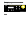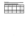
1
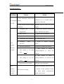
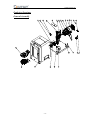
MANUAL
G5 AUTOMATIC GYROSCOPIC MIXER
USER’S MANUAL
C 2006 Copyright Gyro Mixer.
○
All rights reserved.
Printed in the people republic of china
Disclaimer
No part of this book shall be reproduced, stored in retrieval, or transmitted by
any means, electronic, mechanical, photocopying, recording, or otherwise
without the written permission of ZHENG ZHOU SANHUA TECHNOLOGY &
INDUSTRY CO., LTD. While every precaution has been in the preparation of
this book, the publisher assumes no responsibility for errors or omissions.
Neither is any liability assumed for damages resulting from the use of
information contained herein.
This document is the proprietary information of ZHENG ZHOU SANHUA
TECHNOLOGY & INDUSTRY CO., LTD, furnished for customer use only. No
other uses are authorized without written permission from ZHENG ZHOU
SANHUA TECHNOLOGY & INDUSTRY CO., LTD.
ZHENG ZHOU SANHUA TECHNOLOGY & INDUSTRY CO., LTD. reserves
the right to make changes, without notice. To this document and the products it
describes. ZHENG ZHOU SANHUA TECHNOLOGY & INDUSTRY CO., LTD.
shall not be liable for technique or editorial errors or omissions made herein; no
fro incidental or consequential damages resulting from the furnishing
performances, or use of this document.
This manual contains information that is correct to the best of ZHENG ZHOU
SANHUA TECHNOLOGY & INDUSTRY CO., LTD. knowledge. It is intended
to be a guide and should no be considered as a sole source of technique
instruction, replace good technique judgment, since all possible situation can't be
anticipated. If there is any doubt as to exact installation, configuration, and/or
use, calls ZHENG ZHOU SANHUA TECHNOLOGY & INDUSTRY CO., LTD.
The choice of system component is the responsibility of the buyer, and how they
are used cannot be liability of ZHENG ZHOU SANHUA TECHNOLOGY &
INDUSTRY CO., LTD. However, ZHENG ZHOU SANHUA TECHNOLOGY &
INDUSTRY CO., LTD.'s sale team and application engineers are always
available to assist you in making your decision. The latest revision to this
document are available online.
USER’S MANUAL
Table of Contents
Table of Contents………………………………………………………………………0
Preface.…….………………………………………………………………………… 1
General…….………………………………………………………………………… 2
Technical Specifications………… …………………………..……………………… 3
Safety and Environmental Aspects…….……………………...……………………... 4
Structure of the Machine….……..…….……………………...……………………... 5
LCD & Control Panel ………………………………………………………………. .6
Installing the Machine …….………………………………………………………… 7
Buttons on Control Panel …………………………………………………………......8
Volume of Paint Can to be Mixed and Speed Choice…………………………………9
Testing and Operating the Machine…………………………………………………. 10
Warnings.……………………………………………………………………………..12
Maintenance …………………………………………………………………………13
Troubleshooting ……………………………………………………………………...14
Tools …………………………………………………………………………………16
Circuit Diagram ……………………………………………………………………...17
Explosive Drawings…………………………………………………………………18
USER’S MANUAL
Preface
Thanks for purchasing “SANCN” gyroscopic mixer!
This user’s manual provides general information on installation, usage and
maintenance of our gyroscopic mixer. Any improper use will shorten its longevity.
Read this manual completely and carefully before installation, use and maintenance
of the machine. The manual should be kept in a place convenient for future
reference.
For any questions, please do not hesitate to contact our service team.
-1-
USER’S MANUAL
General
G5 Automatic Gyroscopic Mixer is designed for paint mixing with main features:
◆ Ergonomic design and opaque viewing door facilitate observation of
mixing process.
◆ Viewing door with electronic lock to protect the mixer from starting up
while the door is open, and to stop the door from being opened in the
process of operation.
◆ LCD Control Panel serves to display each step of operation or any possible
trouble, convenient for operation.
◆ Integrated Control Board can adjust speeds by multi-segment intelligent
frequency conversion system.
◆ The machine can automatically detect the height of paint can and choose
mixing speed accordingly.
◆ Two motors are installed to control mixing and clamping separately. This
ensures safety and reliability of operation.
◆ Electromagnetic brake mechanism provides good protection to both
operators and paint cans.
◆ Well-closed structure enables the machine to work under more hazardous
surroundings.
◆ The machine is equipped with castors, easy to move.
-2-
USER’S MANUAL
Technical Specifications
Power Supply: Single Phase AC; Voltage and frequency: see the nameplate on the
back of the machine.
Power: 0.75kW
Mixing Speed: Low 125r/min, Middle 150 r/min, High 200r/min
Available Space Between Upper and Bottom Plate: 80mm-452mm
Volume of Paint Can to be Mixed: 1L~20 L
Paint Can to be Mixed: Diameter: 50-360mm; Height: 90mm~400 mm
Mix cycle time:
s,
s,
s ……
Dimensions: 760 x 850 x1033 mm
Net Weight : 198kg
Noise Level: <70dB(A)
-3-
s
USER’S MANUAL
Safety and Environmental Aspects
◆ Do not use a damaged machine. If there is any doubt, please first contact
our service team or your supplier.
◆ Comply with all local safety instructions and regulations.
◆ Read this manual carefully before installing and using the machine.
◆ Keep this manual in a place which is easy to reach and easy to see.
◆ Power Supply: Current:15A; Voltage and frequency: see the nameplate in
the back of the machine. Ambient Working Temperature: 5℃~50℃.
Relative humidity required: 15%-90%.
◆ Never allow young persons to stay close to the machine.
◆ Before using the machine, be sure that the outlet used for power supply is
equipped with earth wire.
◆ Before carrying out any repairs or maintenance, do remember to
disconnect the machine. It is strictly prohibited to perform repairs or
maintenance before disconnecting the machine or when the machine is
working.
◆ Do not use an improper extension cable. Please disconnect the mixer when
not used for a long time.
◆ Adjust the four feet to make sure the machine stands levelly and steadily
on the ground. Keep the castors away from the ground to avoid vibrations.
-4-
USER’S MANUAL
Structure of the Machine
Warning
Control
Label
Board
Clamping
Plate
Main
Switch
Bottom
Plate
Outer
Viewing
Covering
Door
-5-
USER’S MANUAL
Layout of LCD & Control Panel
Nameplate
-6-
USER’S MANUAL
Installing the Machine
For your safety and convenience, we have carefully assembled and tested the
machine.
To install the machine:
◆ Cut apart bindings and unpack wooden crate.
◆ Move the machine to desired working site.
◆ Adjust the feet until all casters leave the ground. Make sure that the
machine is standing steadily. This must be done accurately so that the
machine can function correctly.
Attention!
1. Make sure that the floor is stable and level.
2. Be sure to leave adequate space around the machine for ventilation,
cleaning , inspection and maintenance activities.
3. Read the instructions carefully before using the machine and ensure that any
other users are also aware of these instructions, especially in respect of
safety.
-7-
USER’S MANUAL
Buttons on Control Panel
Stop/Reset
To reset parameters (for example, time and speed), press this
button first. The mixer will stop working and restore to
normal condition. LCD displays “Resetting”.
Release
Press this button to release the clamping plate and LCD
displays “Releasing”.
Clamp
Press this button and the clamping plate begins to clamp.
LCD displays “Clamping”.
+
-
The programmed time will increase or decrease by
on each button press.
and
seconds.
Time range is between
When
pressing
any
seconds
seconds
two
buttons
simultaneously, time will be memorized and “Mixing Time
Saved” will be shown on LCD. When restarting the mixer,
LCD displays the latest set time.
is
Speed
The default mixing time
seconds.
Speed Setting. Press this button to set Low, Medium or High
Speed in cycle. “Middle Speed” is set as default when the
machine just begins to work.
Start
Press this button to start the machine. LCD displays “Mixing”
and time begins to count down.
Emergency Stop
When encountering any abnormities, press this button at once
to stop the machine from working. LCD displays “Emergency
Button Pressed”. To restart the machine, rotate the button
clockwise to release it. Then press “Stop/Reset” button so that
the machine can recover to normal condition.
-8-
USER’S MANUAL
Volume of Paint Can to be Mixed and Speed Choice
Paint Can
High Speed
Medium Speed
Low Speed
Size
200r/min
150r/min
125r/min
Remarks
Minimum
Height:
1L
90mm
5L
Maximum
20L
Weight: 35kg
-9-
USER’S MANUAL
Testing and Operating the Machine
1) Connect the machine and switch it on. Connect the machine to proper
voltage supply. The LCD displays “Please Wait”. Press speed button and
“+、-”button simultaneously and the LCD displays the already mixing
times. Press the “Emergency Stop” button and then release it. The machine
is ready to mix when LCD displays “Ready”. If LCD displays “Emergency
Button Pressed”, release the Emergency Stop button by rotating it
clockwise. If LCD displays “Press Stop/Reset Button”, press the button to
restore the machine.
2) Make sure the paint can is well sealed, the handle is well fastened and
secured to prevent rattling and damage to the can.
3) Press Release or Clamp button to adjust the distance between the clamping
plate and the bottom plate until it fits in with the height of paint can.
4) Open the viewing door, push upwards the lock handle of the bottom plate
and pull out the bottom plate. Put paint can on the bottom plate. Take into
account can size and quantity, make sure that the center of gravity of the
can must as far as possible be in the center of the bottom plate. Push back
the bottom plate. Then try pulling it out and pushing it back again to
confirm if it is well locked. Close the viewing door. If the door is not
completely closed, the LCD will display “Door Open” when the Start
button is pressed.
5) Set mixing time by pressing corresponding button. The initial mixing time
is 180 seconds. Press “+” “-” buttons simultaneously to save the time set
and LCD displays “Mixing Time Saved”.
6) Set proper mixing speed (see “Volume of Paint Can to be Mixed and
Speed Choice”).
7) The clamping plate clamps automatically and the machine starts to mix.
LCD displays “Mixing” and the remaining time. In case the parameter is
incorrect or abnormal, press Stop/Reset button. Then press the Start button.
- 10 -
USER’S MANUAL
8) In the process of mixing, pay attention to the working condition of the
machine. The machine will stop automatically with “Wait Please” on LCD
when the time set is reached. LCD displays “Mixing Finished” and the
clamping plate releases automatically. In case there is any abnormal noise,
press the Emergency Stop button to stop the machine.
9) Open the viewing door, pull out the bottom plate and take out the paint
can.
10) Repeat the above steps 2)-9).
- 11 -
USER’S MANUAL
Warnings
◆ Make sure the paint can is well closed and the handle is well fastened and
secured to prevent rattling and damage to the can.
◆ In case there is any abnormal noise, press the Emergency Stop button to
stop the machine. Find and solve the problem before restarting the
machine.
◆ The paint can should be strong enough and in good shape. It is strongly
recommended not to use severely deformed cans.
◆ The bottom plate must be pushed to the desired position. It is a good habit
of pulling out the bottom plate after placing paint cans on it and then push
it back to confirm that it is locked well. Otherwise it may cause accident.
◆ In the process of mixing, if the speed is too low or there is any abnormity,
press Emergency Stop button immediately. Otherwise this may damage the
motor or the frequency converter.
◆ Do not open the viewing door during mixing. The attempt to open it by
force may cause damage.
◆ Only qualified personnel are allowed to disassemble and test the machine.
◆ Place (a) paint can(s) on the bottom plate so that they are (it is) centered as
well as possible.
- 12 -
USER’S MANUAL
Maintenance
This gyro mixer has been designed to require as little maintenance as possible. Yet
routine maintenance needed to ensure that the machine remains in good working
condition and has a long service life.
Attention!
◆ Before carrying out any maintenance, make sure that the machine has
been unplugged from the socket.
◆ Any unqualified personnel are on no account allowed to disassemble the
machine.
◆ Keep the interior of the machine clean and wipe off paint on the side
screws and the guide shafts with a piece of wet cloth.
◆ Lubricate the side screws and guide shafts every three months.
◆ Lubricate the cone-gear transmission system once every six months.
◆ Open the back cover to check belt tension every year.
- 13 -
USER’S MANUAL
Troubleshooting:
Problems
Causes
Action
Check if the main switch is
1. No connection with power
switched on, or if main cable is
No message supply
properly connected
on LCD
2. Fuse or wire of power supply Replace fuse or wire of power
is broken.
supply.
1. Clamping plate is beyond 1. Shorten the distance between the
height limit.
upper and the lower plates.
2. Belt is loose.
2. Tighten the belt properly.
3. Contactor is broken.
3. Replace the contactor.
4. Connection wire is broken
4. Connect the wire.
5. Clamping
LCD
displays
motor
is 5. Repair or replace clamping
defective.
motor.
6. Inverter is defective.
6. Repair or replace the inverter.
“System
Trouble”
7.
Take
actions
as
install
a
7. The voltage is too high,
voltage-stabilizer
over
to
lower
the
V
voltage.
8.
Take
actions
as
install
a
8. The voltage is too low, voltage-stabilizer to increase the
under
V
voltage.
9. The main motor is broken
LCD
9.Replace the main motor
Switch off machine and restart it in
displays
3 minutes. If this problem occurrs
The inverter is faulty..
“Inverter
for
Trouble”
replace the inverter.
- 14 -
three
times
consecutively,
USER’S MANUAL
The
motor
can
work
but machine The belt is loose
can
Tighten the belt properly.
not
shake.
LCD
1. Emergency Stop button is
Release it.
displays
pressed.
“Emergency
2.The Emergency Stop button Replace the Emergency Stop button
Button
or its connection wire is broken
or reconnect the wire.
LCD
1. The door is not locked.
Lock the door.
displays
2. The inserts of the wire
Pressed”
Insert the wire well or replace the
“Door
become loose or the wire is
Open”
broken.
wire.
Loud noise 1. The machine is not leveled Adjust the feet of the machine to so
and extreme
vibrations
well.
that it can stand levelly and stably..
2. The can(s) is (are) not in the
Adjust the position of paint can(s).
occurred
central position.
during
3. Improper speed selection.
Select the right mixing speed.
mixing.
4. Overloading.
Decrease the weight to be mixed..
Further more, for any problem, please can contact our local distributors or the
manufacturer directly.
- 15 -
USER’S MANUAL
Tools
Descriptions
Quantity
22-24mm open end
1
Spanner
Crosshead Screwdriver
1
- 16 -
Remarks
USER’S MANUAL
Circuit Diagram
- 17 -
USER’S MANUAL
Explosive Drawings
General Assembly
- 18 -
USER’S MANUAL
No.
Part No.
Description
Qty
1
SHH-VI.00-01
Big Pulley,Ribbed Belt
1
2
SHH-VI.00-03
Big Pulley,Clamping
1
750 Motor
1
Small Pullley,Ribbed Belt
1
180 Motor
1
Pulley,Clamping Motor
1
3
4
5
6
YEJ80-4
SHH-VI.00-02
JW6314
SHH-VI.00-04
7
PG11
Water Proof Connector
1
8
A1626
V-Belt
1
Ribbed Belt
1
10
SHH-VI.01
Big Flange Union
1
11
SHH-VI.05
Main Shaft Union
1
Round Nut M45x1.5
1
Lock Washer
1
1
9
12PJ1651(650)
12
GB/T 812-1988
13
GB 858-1988
14
SHH-VI.03
Guide Shaft Union
15
G5.04
G5 Clamping Plate Arm Assembly
16
G5.06
G5 Bottom Plate Arm Assembly
17
G5.07
G5 Active Base Union
1
Shaft End Circlip B28
1
Plain washer 5
5
M5 Locking Nut
5
18
GB892-86
19
GB95-85
20
GB/T 889.1-2000
21
GB/T 5780-2000
22
GB/T 97.2-1985
23
GB/T 93-1987
24
GB/T 5780-2000
Hexagon Bolt M6x20
Plain Washer 6
Spring Washer 6
1
1
4
12
8
Hexagon Bolt M8x30
4
25
GB/T 97.1-85
Plain Washer 8
8
26
GB/T 93-1987
Spring Washer 8
4
27
GB/T 6170-2000
4
28
GB/T 78-2000
29
GB/T78-2000
Nut M8
Inner Hexagon Cone Head Screw
M5x10
Inner Hexagon Cone Head Screw
M6x12
Front Control Board
30
31
GB/T 93-1987
32
GB/T 70.1-2000
33
GB/T17880.1-1999
34
35
GB/T70.1
GB/T6170-2000
36
1
1
1
Spring Washer 5
Inner Hexagon Cylinder Head Screw
M5x16
1
Flat Head Riveted Nut M5
1
Inner Hexagon Cylinder Head Screw
M6x25
4
Nut M6
4
1
2
38
1HS3-2-09-003
Magnet For Cabinet
Door
Crossed Pant Head
Screw M3x8
Side Wanring Label
39
1HS3-2-04-041
Name Plate
1
40
12V NPN
LJ12A3-4-2/BX
Approach Sensor
1
Electrical Lock
1
Circuit Breaker
1
Welded Covering Union
1
37
GB818-85
41
42
DZ47-60 C15
43
G5.02.01
44
1HS3-2-06-006
45
SHH-VI.BZ.01
Front Warning Label
Wooden Case
- 19 -
1
1
1
1
USER’S MANUAL
Main Shaft Assembly
- 20 -
USER’S MANUAL
No.
Part No.
Description
Qty
1
SHH-VI.05-01
Main Shaft
1
2
SHH-VI.05-02
Lower Bearing Holder
1
3
SHH-VI.05-03
Upper Bearing Holder
1
Inner Hexagon Cylinder Head Screw M6x20
8
Clamping Lead Screw
1
Bearing 6004-2z
2
4
GB/T70
5
SHH-VI.05-04
6
GB/T276-94
7
SHH-VI.05-05
Halved Circlip
2
8
SHH-VI.05-06
Lead Screw Bush
1
9
SHH-VI.05-07
Clamping Shaft
1
10
GB/T276-94
Bearing 6002-2z
1
11
GB/T276-94
Bearing 6202-2z
1
12
GB1096-79
Flat Key 5x20
3
13
GB/1096-79
Flat Key C4x18
1
14
GB894.1-86
Circlip (15)for Shaft
1
15
SHH-VI.05-08
Guide Shaft
1
16
GB/T276-94
Bearing 6001-2z
1
17
SHH-VI.05-09
Bush
1
18
GB1096-79
Flat Key
1
19
SHH-VI.05-10
Bevel Pinion
1
20
SHH-VI.05-11
Clamping Driven Bevel Gear
1
21
SHH-VI.05-12
Clamping Driving Bevel Gear
1
22
GB/T 93-1987
Spring Washer 6
2
- 21 -
USER’S MANUAL
Tensioning Pulley Assembly
No.
Part No.
Description
Qty
1
Tensioning Pulley,Ribbed Belt
1
2
Tensioning Pulley
1
Bearing 6002-2z
2
3
GB/T
276-94
4
GB
894.1-86
Circlip(15)for Shaft
1
5
GB
893.1-86
Circlip(32)for Hole
1
- 22 -
USER’S MANUAL
Assembly of Bottom Plate Arm
- 23 -
USER’S MANUAL
No.
Part No.
Description
Qty
1
Lowe Support Arm,G5
1
2
Threaded Nut, Left
1
Pop-up Spring,Bottom Plate
1
4
Pop-up Pin,Bottom Plate
1
5
Num
1
6
Shock Absorbing Pad,Active Base
1
Circlip (40)for Hole
4
8
Line Bearing 25x40x59
2
9
Square Stopper
1
Spring Type Cylinder Pin 8x40
1
11
Side Paneling
4
12
Base Paneling
2
13
Covering Plate,Paneling
2
3
7
10
HB 362-65
GB 893.1-86
GB/T
879.1-2000
14
GB/T
70.1-2000
Hexagon Cylinder Head Screw M5x20
4
15
GB/T
70.1-2000
Hexagon Cylinder Head Screw M5x16
2
16
GB/T
93-1987
Spring Washer 5
2
17
GB/T
819.1-2000
Crossed Counter Head Screw M4x10
- 24 -
14
USER’S MANUAL
Assembly of Clamping Plate Arm
- 25 -
USER’S MANUAL
No.
Part No.
1
G5.04-04
2
SHH-VI.04-01
3
GB/T276-94
4
SHH-VI.04-05
5
GB894.1
6
GB1096-79
7
GB893.1
8
G5.04-06
Description
Upper Support Arm
Small Synchronous Pulley
Qty
1
1
Bearing 6006-2z
1
Nut,Right
1
Circlip(30)For Shaft
1
Plain Key
1
Circlip (55)for Hole
1
1
Shield
9
GB/T818
Crossed Round Head Screw M5x10
2
10
GB95-85
Plain Washer
2
11
322L075
Synchronous Belt
1
12
SHH-VI.06-09
Bottom Paneling
2
13
SHH-VI.06-08
Side Paneling
4
14
SHH-VI.06-10
Covering Plate for Paneling
2
15
GB/T70.1-2000
16
G5.04-08
17
SHH-VI.04-10
18
SHH-VI.04-09
19
GB/T 819.1-2000
20
GB/T 819.1-2000
21
GB/T 93-1987
22
23
24
25
26
Inner Hexagon Cylinder Head Screw M5x20
Position Reflection Plate
SHH-VI.04-02
GB891
GB/T 6170-2000
1
1
Ring
Fastening Screw
Crossed Counter Head Screw M4x16
Crossed Counter Head Screw M4x20
Spring Washer 5
Clamping Plate Shaft Assembly
SHH-VI.04
4
Clamping Plate Assembly
Big Synchronous Pulley
Shaft End Circlip B401
Nut M16
1
2
12
4
1
1
1
1
2
- 26 -
USER’S MANUAL
Assembly of Active Seat
- 27 -
USER’S MANUAL
No.
Part No.
Description
Qty
1
G5.07-01
Fixing Piece,G5
1
2
SHH-VI.07-04
Locking Spring
1
3
SHH-VI.07-05
Limit Bar
1
4
GB879-86
Spring Type Cylinder Pin 6x50
1
Cylinder Guide Shaft ,G5
2
Rotary Handle
1
Inner Hexagon Cone Head Screw
2
Locking Nut M10
1
Bottom Plate Shaft Assembly
1
Bottom Plate Union
1
Guide Shaft End Circlip
4
B18.3.5M - 8 x 1.25 x 16
Socket FCHS -- 16S
4
5
G5.07-06
6
7
GB/T78-2000
8
GB889-1986
9
10
11
12
GB891
- 28 -
USER’S MANUAL
Guide Shaft Assembly
- 29 -
USER’S MANUAL
No.
Part No.
Description
Qty
1
SHH-VI.03-02
Upper Stopper
1
2
SHH-VI.03-01
Guide Shaft
2
3
SHH-VI.03-03
Lower Stopper
1
4
GB/T276-94
Bearng 6002-2z
1
5
GB/T70
Inner Hexagon Cylinder Head Screw M6x20
16
6
SHH-VI.03-04
Left Shield
1
7
SHH-VI.03-05
Right Shield
1
8
SHH-VI.03-06
Front Shield
1
Riveted Pant Head Screw M4x14
2
Crossed Round Head Screw M4x14
2
Spring Washer 4
6
Crossed Round Head Screw M4x8
4
Plain Washer 4
2
Crossed Round Head Screw M5x14
5
2
9
GB/T17880.1-1999
10
GB/T 818-2000
11
GB/T 93-1987
12
GB818-2000
13
GB/T 97.2-1985
14
GB/T 818-2000
15
SHH-VI.03-07
Side Screw Shield
16
GB/T 93-1987
Spring Washer 6
17
18
GB95-85
GB/T 93-1987
16
Plain Washer 5
2
Spring Washer 5
3
- 30 -
USER’S MANUAL
No.
Part No.
Description
Qty
1
SHH-VI.01-01
Big Flange
1
2
SHH-VI.01-03
Shock Absorbing Pad,Big Flange
1
3
SHH-VI.01-02
Big Cone Bevel
1
4
GB/T276-94
Bearing 6009-2z
2
5
GB/T70.1-2000
Inner Hexagon Cylinder Head Screw M5x20
1
6
GB/T70.3-2000
Inner Hexagon Countersunk Screw M5x20
6
7
GB96-85
Big Washer 10
6
8
GB93-87
Spring Washer 10
6
9
GB889-1986
Locking Nut M10
6
- 31 -
USER’S MANUAL
Resetting Parameters of Inverter
For the machine you’ve received, all parameters of the frequency converter have
been preset (read only). To reset these parameters, change 01 of P76 into 00 and
save it. Procedures go as below:
Press [MODE] button until LCD displays [P ].
Press [▲][▼] until the parameter to be reset appears.
Press [ENTER] to be ready to reset the parameter.
Press [▲][▼] to reset the parameter.
Press [ENTER] to save the parameter already reset.
Press [MODE] to return to [F ] (for setting frequency).
P01
P02
P03
P04
P05
P06
P07
P08
P09
P10
P11
P17
P18
P19
P20
Parameter to be Reset
Source of Operational Signals
Motor Stop Mode Setting
Max Operation Frequency
Max Voltage Frequency
Max Output Voltage
Middle Frequency Setting
Middle Voltage Setting
Affect Clamping Force
Min Output Frequency
Min Output Voltage
Home
First Acceleration Time
Affect Big cans Back
First Reduction Time
voltage
Clamping Speed
Too Small Inverter Over
Releasing Speed
Position Seeking Speed
Starting Speed
- 32 -
Affect Clamping Force
USER’S MANUAL
P21
P22
P23
P54
P60
Low Operation Speed
Middle Operation Speed(150)
35(175)
High Operation Speed
Auto Operation Torque Compensation
Affect Clamping Force and Big Cans Back Home
Over Torque Check
Stop running while over
torque
- 33 -
USER’S MANUAL
Zhengzhou Sanhua Technology & Industry Co., Ltd.
Address: XuShui Industrial & Trading Park, Zhongyuan West Road,
Zhengzhou, Henan Province, P. R. China
Postcode: 450042
Tel: 400-6113711
Fax: +86-371-67857166
website: www.santint.com
e-mail: [email protected]
- 34 -