1
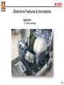
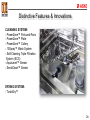
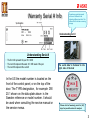
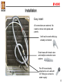
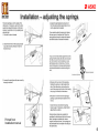
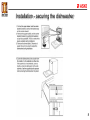
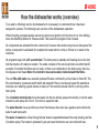
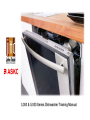
3,000 & 5,000 Series Dishwasher Training Manual Dishwasher Service Training Manual Each section contains: • • • • • • Access/Disassembly Installation/Reassembly Service Tips Access to the service menus Resistance readings Function of components This manual covers the 3,000 & 5,000 series dishwashers. There’s also helpful serial # label information. 1 Distinctive Features & Innovations QUALITY: - 18:9 Stainless Steel Tank, Filter & Spray Arms - Anti-Jam, Auto-Reversing Pump - Galvanized Steel Base Pan - Balanced Door - Check Valve - PEX Water Line (rated 90 year life span) WARRANTY: - Industry Leading - 2 Plus 1 Year - Parts & Labor Protection 2 Distinctive Features & Innovations FLEXIRACKS™: - Industry's Only 4 Level Rack System (High end 5,000 series) - Exclusive Upper Rack - Height Adjustable - Exclusive Middle Rack with 2 Removable Baskets - Exclusive Lower Rack - Adjustable Tines / Upper and Lower Racks - China Guard - 2 Adjustable Stemware Shelves - Wineglass Shelf - Lower Rack - Knife Rack - Cutlery Plus Basket - Knife Guard 2a Distinctive Features & Innovations CAPACITY: - 17 place settings 2b Distinctive Features & Innovations CLEANING SYSTEM: - PowerZone™ Pots-and-Pans - PowerZone™ Plate - PowerZone™ Cutlery - 10Spray™ Wash System - Self-Cleaning Triple Filtration System (SCS) - AquaLevel™ Sensor - SensiClean™ Sensor DRYING SYSTEM: - TurboDry™ 2c Warranty Serial # Info Sometimes a particular model will have 2 different Art #s indicating different part lists. The different Art # indicates a running change Understanding Art. # Understanding Serial # • The first 2 #s represent the year: 09 = 2009 • The next 2 #s represent the week: 25 = 25th week of the year • The next 8 #s represent the serial # In the US the model number is located on the front of the control panel, or on the top of the door. The TYPE designation, for example DW 20.1 shown on the data plate above is the Sweden reference or model number. It should be used when consulting the service manual or the service menus. The serial label is fastened to the right side of the tank Please hold all warranty parts for (60) days for possible return for analysis. 3 Table of Contents Installation…………………………………… 5 How the dishwasher works………………..9 Drain Pump………………………………….14 Fill Valve……………………………………..15 Pressure sensor……………………………21 Circulation Pump…………………………..22 Heater .……………………………………….25 Water Diverter………………………………26 Float Switch…………………………………27 Detergent dispenser……………………….28 Fan assisted dry……………………………29 Door latch/switch…………………………..30 Upper basket rail bearing & holder……..35 Water fill/air break assemblies…………..38 1st edition and is intended for service personnel. Service menus & fault codes…………….41 4 Installation Easy Install: All connections are external. No need to remove kick plates and panels. Unit has line cord with plug already connected Drain hose with check valve and multiple connection size options Pex fill hose already attached to unit, and with 3/8” fitting to connect to water supply 5 Installation – adjusting the springs Printed from Installation manual 6 Installation – adjusting the feet 7 Installation - securing the dishwasher 8 How the dishwasher works (overview) To be able to effectively service the dishwasher it is necessary to understand how it has been designed to operate. The following is an overview of the dishwashers operation: When checking a program always cancel any previous program by turning the unit on, then holding down the Start/Stop button for three seconds. Then select the program to be checked. All components are activated from the control unit, however other actions may have to take place first before a component is activated (for example the heater will not come on if there is no water in the machine). All programs begin with a 25 second drain. The drain pump is partially self-cleaning due to the fact that the direction of rotation is random. The entire contents of the tub should drain out within that 25 seconds. If not either the filters are not clean, or there is an obstruction in the drain pump, the hose, the disposal or air break. Note: It is normal to have some water visible beneath the filters. The unit fills with water via a solenoid operated fill valve controlled by a flow meter or timed fill. The fill is monitored by a pressure switch which will respond if there is not enough water (for example a bowl tips over retaining a good volume of water) or if the machine should overfill, by turning on the drain pump. The circulation motor/pump forces the water into the two (three) spray arms directly, or via the water diverter to each spray arm in turn. The motor is capacitor start. The water diverter has a synchronous motor that drives a disc valve via a gearbox and controls the water to each spray arm. The water is heated via a flow through tubular heater suspended between the sump housing and the Circulation pump. The heater is protected by an auto reset thermal cut-out, and a thermal fuse. 9 How the dishwasher works The temperature that the heated water reaches is controlled by a thermistor (attached to the inner door on 3,000 units and in the sump below the door on 5,00 units). The detergent is dispensed by a solenoid activated dispenser. The first activation dispenses the detergent, the second activation dispenses the rinse aid. Some units have a rinse aid level indicator wired to the control unit. The unit dries by heating the final rinse water to 160 degrees F then dispensing rinse aid into the water. The injection of the rinse aid gives the water a “sheeting action” off of the dishes and makes it easier for the water to evaporate. Drying is further aided by a fan assembly mounted to the inner door. A wax motor opens the vanes allowing moisture from the tank to pass into the condensation tube. A motor then drives a double sided fan blade which draws the moisture laden air out of the tank. 10 Outer Door Removal 1 2 Open the dishwasher door, there are 2 screws at the bottom of the inner door and 3 down each side. 5 or 6 if the unit is an FI model 4 Bracket 3 Remove the 2 bottom screws first 5 Ground wire Remove the screws down each side Lift the door up, and support the top of the outer door and ease the bottom of the door out towards you. Reach underneath, disconnect the ground wire from the bracket and lift up on the bracket slightly to clear the rim of the tank. Inside of outer door Lift door clear 11 Access to lower front components 3,000 series 2 1 3 Plate slide Protection plate After removing the outer door & toe kick, move the plate slide to the left to release the toe kick bracket The following components can be accessed from the front: Drain pump, line cord connector block (with radio interference suppression filter), turbidity sensor (not on all models), and water inlet valve. 4 Remove eight screws, four each side (2 are underneath), to release the protection plate Turbidity Sensor Drain pump Inlet valve Connector block with filter Samples the clarity of the water, will increase or decrease time, temperature and number of rinses 12 Access to lower front components 5,000 series Drain pump Terminal block with filter Turbitity sensor Thermistor 60K Ohms @ room temp. Float Access to drain pump, terminal block with filter, turbitity sensor (if applicable) and the thermistor. 13 Drain Pump 1 To remove the drain pump first disconnect the Molex connector. Grasp the motor and twist towards the front (clockwise) to release the motor/impellor from the housing. To replace, make sure the seal is in place around the pump face then firmly push the motor/impellor and seal into the housing in the vertical position then twist back counterclockwise until it locks in place 2 3 Seal Drain Pump Measures 25 Ohms & uses 32 watts of power. Self cleaning by virtue of the fact that when turned on it will rotate in either direction Connector block with filter 14 Water Fill Valve with flow meter (3,000 series) (front access) 1 Remove the Molex connector from valve 3 2 Unscrew supply hose fitting (turn off water first) 4 500 - 950 Ohms Set hose aside, don’t loose the washer. Slide the valve out of the bracket 15 Water Fill Valve with flow meter (3,000 series) 5 (front access) Connector Flow Meter Remove connector from flow meter 7 Bayonet fitting The flow meter is connected to the rear of the fill valve. The whole assembly can be replaced by removing the hose which goes up to the air break. A new hose clamp will then be needed to reconnect the new assembly. Or the flow meter can be disconnected from the fill valve via the retaining clip or with the bayonet fitting 6 Fill valve is connected to flow meter with a push/turn bayonet type fitting 8 Clip 16 Water level 3,000 series units If the control unit is changed from flow meter to timed fill or vise versa, always check the water level at the lower wash tower Always allow the machine to take in and pump out water a few times before checking the level. Overflow level = 6.5 litres Without Spray arm diverter = 3.1 litres (1.5 mm above the level) With Spray arm diverter = 2.7 litres (0.5 mm below the level) Check the level at the lower wash tower 17 Water Valve (5,000 series) removal (rear access) 1 2 Disconnect pex hose and Molex connector from valve 3 Bend tab at rear of air break Retaining clamp Cut through retaining clamp with cutters The fill valve on the 5,000 series is attached to the air break and is accessed from the rear of the unit. The only way to remove the valve from the air break is to cut through the retaining clamp (the new valve is a kit and will come with a new clamp). Bend the tab at the rear of the air break away from the valve, then pull on the valve to release from the housing 4 Pull valve from air break 18 Water Valve (5,000 series) installation 5 6 7 0.95K Ohms New valve is a kit consisting of a valve and a clamp Note: On the 5,000 series the flow meter is not attached to the fill valve it is located in the air break Attach the clamp to the valve as shown 8 Snap clamp into housing to lock in place Push the spigot of valve into housing making sure the seal is in place 19 Water level 5,000 series units If the control unit is changed from flow meter to timed fill or vise versa, always check the water level at the lower wash tower 20 Pressure sensor Sensor is a push fit into housing and is held with a tab fitting Pressure sensor The pressure sensor is connected to the pressure chamber in the sump. It measures the pressure corresponding to the water level in the machine. In the event of an excessively high water level in the machine the drain pump starts and other components are switched off. When the right level is reached, the program will continue. If the level is not reached within one minute, the program stops and the machine will show a fault indication. 21 Circulation Motor / Pump (3,000 series) The circulation pump & capacitor are accessed from the rear by removing the rear lower panel. Before beginning always drain all water from the sump and disconnect power to the unit Remove four T-15 Torx screws securing the lower rear panel. Carefully pull top of panel out first, then release the tab from the slot in the base of the unit. Screws Screws The circulation Motor has a resistance of 22 ohms and an attached 16 micro farad capacitor. The motor uses 95 watts of power when operating. 22 Circulation Motor / Pump (3,000 series) 1 4 2 Remove ground wire from motor. Remove the Molex connector. There are now two ways to remove the motor/pump assembly. (1) disengage the motor/pump from the pump housing by grasping the motor and turning it counter clockwise a tad so that the locking tab can be lifted up, then twist the motor clockwise to remove from the pump housing. (2) Remove the hose clamp (not reusable) which connects the pump to the water diverter valve assembly (or if no diverter the blank housing) then pull the whole unit from the heating element (it is a pressure fit, no clamp) 3 5 23 Circulation Motor / Pump (5,000 series) 32 Ohms Motor/pump Water Diverter Circulation motor/pump is removed in the same manor as the 3,000 series, however there is less room to maneuver due to the taller tank. It may be easier to remove and replace the motor/pump as a complete assembly. 24 Heating Element 1 2 Access to the heating element is achieved from the rear of the unit in the same manor as the circulation motor/pump. The heating element is suspended between the circulation pump housing and the sump housing and is secured with rubber seal inserts. It is a push fit and there are no clamps. The circulation motor will have to be removed first in order to pull the heating element off of the sump. Before removing the heating element disconnect the ground wire and the Molex connector. Caution Connection rods run from the heater to the Molex on the outside of the casing and are hot all the time so make sure the power is off before removal. Heating Element is 1200 Watts Resistance 12 Ohms 25 1 Water Diverter Valve Access to the water diverter valve is achieved from the rear of the unit in the same manner as the circulation motor/pump and heater. Ease the two tabs on both sides, out slightly and pull down on the assembly. Disconnect the three wire connector going to the terminal block of the diverter. 2 Before installing the new diverter be sure to install the “O” rings from the old one onto the new one (see illustration) or the new unit will leak. Resistance reading between terminal 2-3 is 2,600 Ohms 26 Float switch 1 The float switch is mounted in the sump housing. In the event of water overflowing into the base pan, a Styrofoam float rises up and activates a micro switch turning on the drain pump. Access to the switch is from the rear and other components may have to be removed to get to the switch. To remove the switch from the housing disconnect the three wires going to the switch. Push a screwdriver through the access hole and ease the switch off the support pegs. 2 3 27 Detergent/Rinse Aid Dispenser 1 2 3 Thermistor 25K Ohms Solenoid 300 Ohms Detergent & rinse aid dispensers are combined into one assembly & is fastened to the inner door with 2 clamps 4 Disconnect Molex to solenoid Remove thermistor from right side of lower clamp (3,000 series only) Disconnect Molex to rinse aid sensor (if applicable). 5 6 Remove the remaining screws holding the upper and lower clamps. Open the door and lift assembly from inner door 28 Fan Assisted Dry Assembly 1 Wax motor opens vanes to condensation tube 1.1 K Ohms 2 drives 2 sided 2Motor fan to remove moist air 3 from tank Some units have in addition, a Motor 180 Ohms humidity sensor which turns off the fan based on comparison of outside & inside humidity levels To remove assembly, disconnect Molex connector from wax motor and fan motor. From inside the door remove the two screws holding stainless assembly cover. Grasp the inner black cover and twist counterclockwise. Remove unit from door. 4 5 6 29 Door latch/switch assembly 1 2 3 After removing the outer door remove the 2 screws on top of the inner door. Ease the control panel from the tabs in the top of the inner door. Release wiring to door switch and lift latch from cradle. 4 5 6 To remove door micro switch, bend tab on switch assembly and slide switch up and out of the housing. 30 Control board removal and installation 1 2 3 After removing the wire connections and removing control panel from the unit, lay it down on a protected flat surface. Not all control boards can be removed from the panel intact, for example the FI unit shown above. In this case separate the casing by using a flat blade screwdriver and prying the tabs apart see (2) 4 5 6 The new control board will install into the control panel as a complete assembly. Insert the touch pad end into the control panel first then snap the unit into place. 31 Rewiring control board If wiring from a component to the control board or from the control board to a component, check with the wiring diagram for correct location of connectors. The wiring diagram mirrors the circuit board for easy reference. Note: When replacing a control board check the Wax motor, diverter motor and heater to make sure that a short in one of these components did not cause the control to fail. Otherwise the new board will also fail. 32 Control board wiring and component values Schematic for all 3,000 series units Dispenser 300 Ohms: Circulation pump 22 Ohms: Water diverter valve 2600 Ohms: Filter 1 mega Ohm: Heating element 12 Ohms: Fill valve 950 Ohms: Thermistor 25,000 Ohms: Wax actuator 1100 Ohms: Fan motor 180 Ohms: Drain pump 25 Ohms 33 Control board wiring and component values Schematic for all 5,000 series units Schematic for all Dispenser Ohms: units Circulation pump 32 Ohms: Water diverter valve 2600 Ohms: Filter 1 mega Ohm: Heating element 12 5,000300 series Ohms: Fill valve 950 Ohms: Thermistor 60,000 Ohms: Wax actuator 1100 Ohms: Fan motor 180 Ohms: Drain pump 25 Ohms. 34 Upper rack rail bearings and holders (removal) 11 43 2 To remove ball bearing holder for upper rack rail, use a flat blade screwdriver or needle nose pliers and remove the rear rail stop by easing the bottom of the stop out of the notch in the rail. Now slide the rail out of the track. Slide out the ball bearing plastic holder which should contain 4 bearings. Check the bottom of the tank for broken off plastic pieces or ball bearings which may have fallen out. 2 4 35 Upper rack rail bearings and holders (install) 6 7 8 The replacement bearing holders come in a kit with the ball bearings. The bearing holder comes flat, insert the ball bearings into the holder, then bend the holder to form the correct shape (see illustration). 9 Slide the newly assembled bearing holder into the track, then slide the rack rail into the bearing holder. Finish off by reinstalling the rear rail stop. 10 Rail stop 36 Filters and sump drain cap 1 2 Remove strainer basket 3 Rotate fine mesh filter counter clockwise . Lift out Strainer and filters must be kept clean to ensure good draining and clean dishes. 4 5 Cap removed Remove strainer: With cap removed from sump there is access to the impellor of the drain pump for clean out 6 Cap Sump drain cap sits down in the sump area inside the outlet to the drain pump This cap must be in place in order for the machine to drain correctly 37 Water fill/air break assembly (5,000 series) 3,000 series is the same but does not have the fill valve & flow meter Unit removed from dishwasher Cover Flow meter Front Fill valve The air break contains the fill valve and the flow meter, it is fastened to the side of the tank with the cover (from the inside of the tank) and a single screw on the outside. In addition it is held in place on the outside of the tank with the base side supports. There are two large screws which go through the tank wall and into these side supports effectively squeezing it in place. Flow meter Rear 38 Water fill/air break assembly (5,000 series) 3,000 series is the same but it does not have the fill valve & flow meter 1 Screw 2 3 Screw With a straight blade screwdriver rotate cover counter clockwise to remove. Remove single screw on outside and two from the inside of the tank. 4 55 66 Block side wall away from tank, and slide the air break out from its location. When reinstalling make sure the seal is in place and use a clamp to pull side support to tank so that screws will engage. 39 Service Tips – Replacing hose clamps 3 -1/4” 1 -3/4” 2 -1/4” 8063262 8063607 1 -1/2” 1 -1/4” 8052083 8052239 8056471 1” 7/8” ½” 8054196 8052730 8052731 Special Hose Clamp Pliers Part # 7281370 40 Although the controls for each model may be on the front of the machine or on the top of the door. The main power switch is always on the top of the door on the far left side Variant menu DW 20.1 Main power switch Variant ‘A’ with 2 program options shown as an example. For this control panel configuration choose L1 flashing, variant ‘A’. If the control is replaced the machine will automatically be in the variant setting menu when the power is turned on. Press the program button repeatedly, the display will alternate between pan symbol (L1) flashing(variant A), and the shower symbol (L4) flashing(Variant B). Choose the variant, then confirm this selection by pressing the start/stop button. The program will then revert automatically to the main menu. Once the control board variant has been set, it is still possible to return to the variant menu and change it again. (useful if it has been programmed incorrectly). To do so, turn off the main power switch. Wait at least 5 seconds, Press and hold the Program and Start buttons, turn on the main power switch, wait a second then release the Program and Start buttons, then within 5 seconds press the Start button 3 times in quick succession. Use the Program button to select a different variant. Confirm by pressing the Start button. Program returns to the main menu. 41 Before entering the service menu always cancel the currently selected program first, by pressing the power button to turn the unit on then holding down the start/stop button for three seconds. Main power switch Service menu DW 20.1 Although the controls for each model may be on the front of the machine or on the top of the door. The main power switch is always on the top of the door on the far left side The only thing that can be changed in the service menu of the 20.1 units is the water intake. It can be changed from flow meter fill, to timed fill. To activate the service menu – turn off the main power switch. Wait for at least 5 seconds, keep the program and start buttons depressed, then turn on the main switch, then release the program and start buttons. The program button, the start button and L7 flashes. The water intake can now be adjusted by pressing the program button once again. L7 will be flashing continuously during this operation. If L1 is extinguished the water is controlled by the flow meter, if it is lit the water is controlled by time. Confirm the choice by pressing the start button. The program will return to the main menu. 42 Variant menu DW 20.2 Although the controls for each model may be on the front of the machine or on the top of the door. The main power switch is always on the top of the door on the far left side Main power switch 3 Button option 5 Button option If the control is replaced the machine will automatically be in the variant setting menu when the power is switched on for the first time. Fill the machine with approx. 1 liter of water. Press the program button repeatedly until the desired variant is selected (there are only 2 options. Display shows 1(variant 1 Express option, also good for 3 button control) or display shows 2(variant 2 Super rinse option). Choose 1. Confirm choice by pressing the start button. The machine will now sense the presence of the turbidity and pressure sensors and the spray arm divider. The program then reverts back to the main menu. Once the control board variant has been set, it is still possible to return to the variant menu and change it again. (useful if it has been programmed incorrectly). To do so, turn off the main power switch. Wait at least 5 seconds, Press and hold the Program and Start buttons, turn on the main power switch, wait a second then release the Program and Start buttons, then within 5 seconds press the Start button 3 times in quick succession. Use the Program button to select a different variant. Confirm by pressing the Start button. Program returns to the main menu. 43 Service menu DW 20.2 Before entering the service menu always cancel the currently selected program first, by pressing the power button to turn the unit on then holding down the start/stop button for three seconds. Main power switch Turn off the main switch, wait for at least 5 seconds. Keep the program and start buttons depressed and turn on the main switch, release the program and start buttons at once. The display lights up after 5 seconds. The most recent fault will appear in the display F1, F2, etc. Press the program button and index through the following components: 1. Inlet valve, 2. Salt valve (not applicable), 3. Detergent dispenser, 4. Circulation pump, 5. Heating element & circulation pump (max 167 F), 6. Fan, 7. Drain pump. 44 Service menu DW 20.2 Before entering the service menu always cancel the currently selected program first, by pressing the power button to turn the unit on then holding down the start/stop button for three seconds. Main power switch Water intake adjusting (after week 16, 2005) Press the program button until “1” appears in the display. Press the program button and index through the following: Display shows 0: Normal water intake, 1: increase 5%, 2: increase 10%, 3: increase 15%, 4: Time controlled water intake, 5: Increase 5% on time control, 6: Increase 10% on time control, 7: 15% increase on time control. Confirm choice by pressing start. The program returns to the main menu. Prior to week 16, 2005) 0: Normal water intake, 1: water reduced 15%, 2: water reduced 10%, 3: water reduced 5%, 4: Time controlled water intake, 5: Water increased 5%, 6: Water increased 10%, 7: Water increased 15%. Confirm choice by pressing start. Program returns to the main menu. 45 Fault codes DW 20.2 (the consumer may see) See page 59 for fault codes that may appear in the service menu for the technician to view 46 Variant menu DW 20.3 5 Button design Main power button 3 Button design If the control is replaced the machine will automatically be in the variant setting menu when the power is switched on for the first time. Fill the machine with approx. 1 liter of water. Press the program button repeatedly until the desired variant is selected . L1 Lit: Express option and 3 button design. L2 Lit: Super rinse option (Choose L1), Confirm choice by pressing the Start button. The machine will now sense the presence of the turbidity and pressure sensors and the spray arm divider. The program then reverts back to the main menu. Once the control board variant has been set, it is still possible to return to the variant menu and change it again. (useful if it has been programmed incorrectly). To do so, turn off the main power switch. Wait at least 5 seconds, Press and hold the Program and Start buttons, turn on the main power switch, wait a second then release the Program and Start buttons, then within 5 seconds press the Start button 3 times in quick succession. Use the Program button to select a different variant. Confirm by pressing the Start button. Program returns to the main menu. 47 Service menu DW 20.3 Before entering the service menu always cancel the currently selected program first, by pressing the power button to turn the unit on then holding down the start/stop button for three seconds. Main power switch Turn off the main switch, wait for at least 5 seconds. Keep the program and start buttons depressed and turn on the main switch, release the program and start buttons. The most recent fault will be indicated as L1 – L6. Press the program button and index through the following components: 1. Inlet valve, 2. Salt valve (not applicable), 3. Detergent dispenser, 4. Circulation pump, 5. Heating element & circulation pump (max 167 F), 6. Fan, 7. Drain pump. 48 Before entering the service menu always cancel the currently selected program first, by pressing the power button to turn the unit on then holding down the start/stop button for three seconds. Service menu DW 20.3 Main power switch To adjust the water intake. Keep the program button depressed for three seconds to adjust the water intake. After week 16, 2005. Press the program button and index through the following: L1-L6 extinguished normal volume. L1 lit: water increased by 5%, L2 lit: water increased by 10%, L3 lit: Time controlled intake, L4 lit: Increase time control by 5%, L5 lit: Increase time control by 10%, L6 lit: Time control increase by 15%. Confirm choice by pressing Start button. The program returns to the main menu Before week 16, 2005. Press the program button and index through the following: L1-L6 extinguished: Normal volume. L1 lit: Water reduced by 10%, L2 lit: Water reduced by 5%, L3 lit: Time controlled intake, L4 lit: Water increased by 5%, L5 lit: Water increased by 10%, L6 lit: Water increased by 15%. Confirm choice by pressing start button. The program returns to the main menu. 49 Fault codes DW 20.3 (the consumer may see) See page 59 for fault codes that may appear in the service menu for the technician to view 50 Variant menu DW 20.4 Main power switch If the control is replaced the machine will automatically be in the variant setting menu when the power is switched on for the first time. Fill the machine with approx. 1 liter of water. Press the program button repeatedly until the desired variant is selected . Variant 1: Variant with Menu/Set. Variant 2: Variant with Temperature/Drying selection. Choose Variant 1: Confirm choice by pressing the start button or the menu button. The machine will now sense the presence of the turbidity and pressure sensors and the spray arm divider. The program then reverts back to the main menu. Access to Special settings menu Turn off the main switch, wait at least 5 seconds. Keep Set button depressed. Turn on the main switch, then release Set button. Select the status with Set button, proceed with menu button. Language can be changed, child lock, acoustic signal volume etc. Once the control board variant has been set, it is still possible to return to the variant menu and change it again. (useful if it has been programmed incorrectly). To do so, turn off the main power switch. Wait at least 5 seconds, Press and hold the Program and Start buttons, turn on the main power switch, wait a second then release the Program and Start buttons, then within 5 seconds press the Start button 3 times in quick succession. Use the Program button to select a different variant. Confirm by pressing the Start button. Program returns to the main menu. 51 Before entering the service menu always cancel the currently selected program first, by pressing the power button to turn the unit on then holding down the start/stop button for three seconds. Service menu DW 20.4 Main power switch Turn off the main switch, wait for at least 5 seconds. Keep the Set and Menu buttons depressed and turn on the main switch, release the Set and Menu buttons. Press Set for information about: Date code and serial number, control unit date code, software version, most recent fault, next most recent fault. Press Menu to access component diagnostics. Press Set to activate the following components: 1. Inlet valve (shows water intake volume), 2. Salt valve (not applicable), 3.Detergent dispenser, 4. Circulation pump ( displays turbidity in volts), 5. Heating element and circulation pump (max 167 F) shows temperature, 6. Fan. (display shows humidity sensor value), 7. Drain pump. (display shows pressure sensor reading, 0.5-3.5 VDC). Note: The door will have to be opened and closed for each component check. 52 Before entering the service menu always cancel the currently selected program first, by pressing the power button to turn the unit on then holding down the start/stop button for three seconds. Service menu DW 20.4 Main power switch To adjust the water intake: (machines manufactured week 16, 2005 and later) Press menu to access water intake setting, press set to adjust the water intake. Display 0: Normal water intake. Display + 5%: Water intake increased by 5%. Display + 10%: Water increased by 10%. Display + 15%: Water increased by 15%. Display time: Time controlled water intake. Display time + 5%: Time controlled water is increased by 5%. Display Time + 10%: Time controlled water is increased by 10%. Display Time + 15%: Time controlled water is increased by 15%. Press Start to store setting. The program returns to the main menu. Prior to week 16, 2005: Display 0: Normal. Display -15%. Display -10%. Display -5%. Display Time. Display + 5%. Display + 10%. Display + 15%. Press Start to store the selected setting. The program returns to the main menu 53 Fault codes DW 20.4 (the consumer may see) See page 59 for fault codes that may appear in the service menu for the technician to view 54 Variant menu DW 20.5 Main power switch If the control unit is replaced, the machine will automatically be in the variant setting menu when the power supply is switched on for the first time. Fill the machine with approx. 1 liter of water. Press the program button repeatedly until the desired variant is selected. There are two choices (1): Express option. (2): 3 in 1 option. Choose 1. Confirm choice by pressing Start. The machine senses the presence of the turbidity and pressure sensors and the spray arm divider, The program then reverts back to the main menu. Once the control board variant has been set, it is still possible to return to the variant menu and change it again. (useful if it has been programmed incorrectly). To do so, turn off the main power switch. Wait at least 5 seconds, Press and hold the Program and Start buttons, turn on the main power switch, wait a second then release the Program and Start buttons, then within 5 seconds press the Start button 3 times in quick succession. Use the Program button to select a different variant. Confirm by pressing the Start button. Program returns to the main menu. 55 Service menu DW 20.5 Before entering the service menu always cancel the currently selected program first, by pressing the power button to turn the unit on then holding down the start/stop button for three seconds. Main power switch Turn off the main switch, wait for at least 5 seconds. Keep the Program and Start buttons depressed and turn on the main switch, release the Program and Start buttons. Press Program button to index through the following components. 1. Inlet valve 2. Salt valve (not applicable) 3.Detergent dispenser 4. Circulation pump 5. Heating element and circulation pump (max 167 F) 6. Fan 7. Drain pump. 56 Service menu DW 20.5 Before entering the service menu always cancel the currently selected program first, by pressing the power button to turn the unit on then holding down the start/stop button for three seconds. Main power switch To adjust the water intake: Press program selector for 3 seconds to access water intake setting, press program button again to step through. Display 0: Normal water intake. Display shows 1: Water intake increased by 5%. Display shows 2: Water increased by 10%. Display shows 3: Water increased by 15%. Display shows 4: Time controlled water intake. Display shows 5: Time controlled water is increased by 5%. Display shows 6: Time controlled water is increased by 10%. Display shows 7: Time controlled water is increased by 15%. Press Start to store setting. The program returns to the main menu. 57 Fault codes DW 20.5 (the consumer may see) See page 59 for fault codes that may appear in the service menu for the technician to view 58 Fault codes DW 20.1, 2, 3, 4 & 5 (fault codes the service technician may see in the service menu) In the fault codes below, “L” denotes LED and “F” denotes fault code on the display. LED L1/Fault code F1, Temperature stop fault (no indication in DW20.1) The temperature rise is less than 5 degrees C in ten minutes. The program exits from the heating stage and continues in the process. This fault code will only show in the service menu. Check: Element, thermistor, water level, circulation pump, control unit and wiring. LED L2/Fault code F2, Overfilling Too much water in the machine (pressure sensor) or float activated. If the water has not been evacuated within 60 seconds, the program will be interrupted (the drain pump will be activated). Check: Drain pump (blockage in hoses), flow sensor, inlet valve, leakage, wiring. 59 Fault codes DW 20.1, 2, 3, 4 & 5 (fault codes the service technician may see in the service menu) LED L3/Fault code F3, Thermistor fault (no indication in DW20.1) Interruption in the heating or temperature more than 80 degrees C. The program exits from the heating stage and continues in the process. Indication only in the service menu. Check: Thernistor, control unit. LED L4/Fault code F4, Water intake fault (no indication in DW20.1) Less than 80 pulses received by flow sensor within 60 seconds, or the correct number of pulses is not achieved within 225 seconds. Program interrupted. Check: Water supply, flow sensor, inlet valve, wiring 60 Fault codes DW 20.1, 2, 3, 4 & 5 (fault codes the service technician may see in the service menu) LED L11/Fault code F5, Valve leakage (no indication in DW20.1) More than 80 pulses detected when the inlet valve is deactivated. Certain models attempt to remedy the leak first. Any program in progress is interrupted (drain pump activated). Check: Leakage through inlet valve, flow sensor. LED L12/Fault code F6, Pressure sensor fault Output signal more than 4.8 V. The program continues. Indication only in the service menu. Check: Pressure sensor, control unit and wiring 61 Fault codes DW 20.1, 2, 3, 4 & 5 (fault codes the service technician may see in the service menu) LED L1+ L2/Fault code F7, Pumping out fault (machines with pressure sensor) Water not evacuated after 120 seconds pumping out. Program interrupted. Check: Drain pump, hoses, installation of drain hose, control unit and wiring. LED L1 + L3/Fault code F8, Blocked filter The pressure sensor senses excessively low pressure during the final rinse. Indication after the end of the program. Check: Filter, sump (pressure chamber), pressure sensor. 62 Fault codes DW 20.1, 2, 3, 4 & 5 (fault codes the service technician may see in the service menu) LED L1 + L4/Fault code F9, Circulation fault The pressure sensor senses excessively low pressure (e.g. no water in the machine) or excessively high pressure (e.g. the circulation pump is defective). The program exits from the heating stage and continues in the process. Indication only in the service menu. Check: Circulation pump, filter water level, pressure chamber and pressure sensor. LED L1 + L11/Fault code FA, Turbidity sensor fault Indication only in the service menu. The machine assumes high turbidity for “choice of route” in the automatic program. Check: Water quality, filter, turbidity sensor, drain system. 63 Fault codes DW 20.1, 2, 3, 4 & 5 (fault codes the service technician may see in the service menu) LED L1 + L12/Fault code FB, Spray arm diverter fault Position contact is continuously closed or open. The program proceeds. Indication only in the service menu. Check: Spray arm diverter (function of gearbox, contacts and wiring). LED L6/Rinse aid indication (DW20.5) LED L7/Fault code, Door open LED L7/Fault code, Close door 64 Variant menu DW 70.1 Main power switch Variant 2 Variant 1 If the control is replaced the machine will automatically be in the variant setting menu when the power is turned on. Press the program button repeatedly, the display will alternate between pan symbol (L1) flashing, (variant 1) and the shower symbol (L4) flashing, (variant 2). Choose the variant, then confirm this selection by pressing the start/stop button. The program will then revert automatically to the main menu. Once the control board variant has been set, it is still possible to return to the variant menu and change it again. (useful if it has been programmed incorrectly). To do so, turn off the main power switch. Wait at least 5 seconds, Press and hold the Program and Start buttons, turn on the main power switch, wait a second then release the Program and Start buttons, then within 5 seconds press the Start button 3 times in quick succession. Use the Program button to select a different variant. Confirm by pressing the Start button. Program returns to the main menu. 65 Before entering the service menu always cancel the currently selected program first, by pressing the power button to turn the unit on then holding down the start/stop button for three seconds. Service menu DW 70.1 Main power switch To activate the service menu – turn off the main power switch. Wait for at least 5 seconds, keep the program and start buttons depressed, then turn on the main switch, then release the program and start buttons. L7 flashes. Press the program button to activate the component test. These are activated in order after each button press: 1. Inlet valve, 2. Salt valve (not applicable), 3. Dispenser, 4.Circulation motor, 5, Circulation motor and element (max 167 F), 6. Fan and wax motor, 7. Drain pump. Adjust water intake (done in service menu) Press and hold the program button for three seconds. L1 unlit: Fill controlled by flow meter. L1 lit: Time controlled fill. Confirm selection by pressing Start. The program returns to the main menu. 67 Fault codes DW 70.1 (the consumer may see) Indication Type of fault L2 flashing Too much water in the dishwasher: Pressure sensor or float activated If water not evacuated in 60 secs. The drain pump will be turned on. L5 flashing Leaking valve: water intake detected when the valve is deactivated. Any current program stopped and drain pump activated. Action Check drain pump (blockage in hoses), flow meter, inlet valve, leakage, wiring Check leak through inlet valve and flow meter. See page 81 for fault codes that may appear in the service menu for the technician to view 68 Variant menu DW 70.3 When the power is switched on for the first time after replacing the control unit, the variant settings menu is displayed. Press the program button until the desired variant is selected: L1 flashes: Variant 1 = Time saver L2 flashes: Variant 2 = Super rinse option L3 flashes: Variant 3 = Tab Confirm selection by pressing Start. The machine detects the presence of a turbidity sensor, a pressure sensor and a sprat arm divertor.The program returns to the main menu. Once the control board variant has been set, it is still possible to return to the variant menu and change it again. (useful if it has been programmed incorrectly). To do so, turn off the main power switch. Wait at least 5 seconds, Press and hold the Program and Start buttons, turn on the main power switch, wait a second then release the Program and Start buttons, then within 5 seconds press the Start button 3 times in quick succession. L1, L2, or L3 flashes on the display depending on the previous setting. Use the Program button to select a different variant. Confirm by pressing the Start button. Program returns to the main menu. 69 Before entering the service menu always cancel the currently selected program first, by pressing the power button to turn the unit on then holding down the start/stop button for three seconds. Service menu DW 70.3 Main power switch Turn off the main power switch. Wait at least 5 seconds. Press and hold the program and start buttons, turn on the main switch, wait for the teardrop symbol to light on the right side of control, release the program and start buttons. L10 AND L11 flash. Most recent fault if there are any is indicated by L1 – L6 Before activating the component test it is necessary to manually activate the door latch so that the door switch will be closed with the door open. Then follow the sequence below Press program button to activate the component test. These are activated in order after each button press. 1. Inlet valve L1 and L2 lit 2. Salt valve (not applicable). 3. Dispenser. L4 lit 4. Circulation pump. L5 lit 5. Circulation pump and element (max. 167 F) L6 lit 6. Fan and wax motor. L1 and L2 lit 7. Drain pump. L1, L2 and L3 lit 70 Before entering the service menu always cancel the currently selected program first, by pressing the power button to turn the unit on then holding down the start/stop button for three seconds. Service menu DW 70.3 Adjust water Intake (done in service menu) Press and hold the program button for three seconds. The water can now be adjusted as follows: Press the program button to step through: L1-L6 unlit: Normal water volume L1 lit: Water increase by 5%. L2 lit: Water increase by 10% L3 lit: Time controlled water intake L4 lit: Time controlled water increase by 5% L5 lit: Time controlled water increase by 10% L6 lit: Time controlled water increase by 15 Confirm selection by pressing Start. The program returns to the main menu. 71 Fault codes DW 70.3 (the consumer may see) See page 81 for fault codes that may appear in the service menu for the technician to view 72 Variant menu DW 70.4 Main power switch Total reset After replacing the control unit, the machine will automatically perform a total reset, which will detect the presence of the machine’s sensors and spray arm diverter. Special settings Turn on the main power switch, press the Menu button (S4) a few times until the special settings are displayed. The following settings are available: Language, child safety catch, program end signal, button tones, temperature (C or F), water hardness setting. Press S3 until the desired setting is shown. Confirm with S4. The program stores the settings and returns to the main menu. Display mode Press and hold S4 with the main power switch turned on. Scrolling text is displayed: Turbo Drying…Super Cleaning System…Auto Wash…Flexi Racks…Power Zone…8 Steel… Cancel by pressing the power switch. 73 Before entering the service menu always cancel the currently selected program first, by pressing the power button to turn the unit on then holding down the start/stop button for three seconds. Service menu DW 70.4 Main power switch Turn off the main power switch, wait at least 5 seconds. Press and hold the Program and Start buttons then turn on the main power switch. Release the Program and Start buttons. The service menu has four sub menus:1. Machine and fault information. 2. Component diagnostics. 3. Adjust water intake. 4. Adjust LCD contrast. Press S4 to browse between these menus. Press S3 to enter the selected sub menu and S4 to return. Machine and fault information displays: (browse with S3) 1. Date code (year/week) of control unit. 2. Software version. 3. Most recent fault. 4. Second most R, fault. Before activating the component test it is necessary to manually activate the door latch so that the door switch will be closed with the door open. Then follow the sequence below Activating component diagnostics: (browse with S3) 1. Inlet valve 2. Salt valve (not applicable) 3. Detergent dispenser 4. Circulation pump 5. Heating element and circulation pump (max 167 F) 6. Fan 7. Drain pump. 74 Before entering the service menu always cancel the currently selected program first, by pressing the power button to turn the unit on then holding down the start/stop button for three seconds. Service menu DW 70.4 Main power switch Adjust water intake (browse with S3) Display 0: Normal water intake volume. Display + 5%: Volume increases by 5%. Display + 10%: Volume increases by 10%. Press Start to store settings Display + 15%: Volume increases by 15%. Display Time: Time controlled water intake. Display + 5%: Time controlled intake increases by 5%. Display +10%: Time controlled intake increases by 10%. Display + 15%: Time controlled intake increases by 15% 75 Fault codes DW 70.4 (the consumer may see) See page 81 for fault codes that may appear in the service menu for the technician to view 76 Variant menu DW 70.5 Main power switch When the main power switch is turned on after replacing the control unit, the variant setting menu is displayed. Press the program button until the until the desired variant is selected. The display shows 1 and L1 flashes. Variant 1 = Time saver The display shows the number 2 and L2 flashes. Variant 2 = with Super rinse The display shows the number 3 and L3 flashes. Variant 3 = with Tab The display shows the number 4 and L4 flashes. Variant 4 = with Time program Choose variant 4. Confirm selection by pressing Start. The machine detects the presence of a turbidity sensor, a pressure sensor and a spray arm diverter. The program returns to the main menu. Once the control board variant has been set, it is still possible to return to the variant menu and change it again. (useful if it has been programmed incorrectly). To do so, turn off the main power switch. Wait at least 5 seconds, Press and hold the Program and Start buttons, turn on the main power switch, wait a second then release the Program and Start buttons, then within 5 seconds press the Start button 3 times in quick succession. L1, L2, L3 or L4 flashes on the display depending on the previous setting. Use the Program button to select a different variant. Confirm by pressing the Start button. Program returns to the main menu. 77 Before entering the service menu always cancel the currently selected program first, by pressing the power button to turn the unit on then holding down the start/stop button for three seconds. Service menu DW 70.5 Main power switch Turn off the main power switch, wait at least 5 seconds. Press and hold the Program and Start buttons. Turn on the main power switch, wait until the LEDs have lit, release the Program and Start buttons. The most recent fault code if there is one will be shown in display D2 AND D3. Press the Program button to activate the component test. These are activated in order after each button press and are shown in D3. 1. Fill valve and mixer valve 2. Fill valve only 3. Salt valve (not applicable) 4. Dispenser 5. Circulation pump 6. Circulation pump and element (max 167 F) 7. Fan and Wax motor 8. Drain pump 78 Before entering the service menu always cancel the currently selected program first, by pressing the power button to turn the unit on then holding down the start/stop button for three seconds. Service menu DW 70.5 Main power switch Adjusting the water intake (in service menu Press the Program button for three seconds to activate the menu for setting the water intake. Then use the Program button to step through. The display shows: P:0 = Normal water intake volume. P:5 = Water increases by 5%. P:10 = Water increases by 10%. P:15 = Water increases by 15%. T:0 = Normal water intake. T:5 = Water increases 5%. T:10 = Water increases 10%. T:15 = Water increase by 15%. P = water intake controlled by flow meter. T = water intake time controlled. Confirm selection by pressing Start. The program returns to the main menu. . 79 How the dishwasher works (Quick wash 5,000 series) If the component test in the service menu is not sufficient to identify a fault, you can run the “Quick Wash” program on any of the 5,000 series units. Compare the results with the flow description on the right, if they are in agreement this indicates a correctly functioning control unit 66 Fault codes DW 70.5 (the consumer may see) See page 81 for fault codes that may appear in the service menu for the technician to view Consumer may see 1 minute shown in display at the end of the cycle. No action is required. The program took longer than estimated. The next time the program is run the corrected time will be shown. 80 Fault codes DW 70.1, 3, 4 & 5 (fault codes the service technician may see in the service menu) 81 Fault codes DW 70.1, 3, 4 & 5 (fault codes the service technician may see in the service menu) 82 Fault codes DW 70.1, 3, 4 & 5 (fault codes the service technician may see in the service menu) 83 Fault codes DW 70.1, 3, 4 & 5 (fault codes the service technician may see in the service menu) 84 Fault codes DW 70.1, 3, 4 & 5 (fault codes the service technician may see in the service menu) 85