1
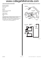
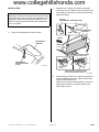
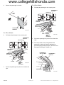
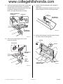
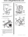
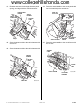
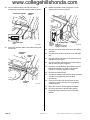
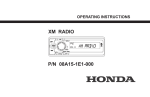
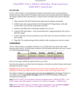
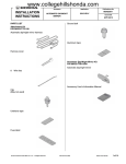
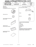
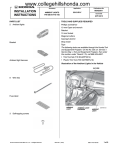
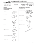
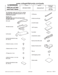
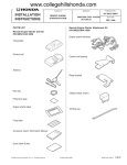
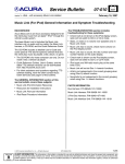
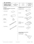
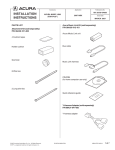
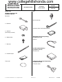
www.collegehillshonda.com
INSTALLATION
INSTRUCTIONS
PARTS LIST
Accessory
Application
XM RADIO SYSTEM
2014 CIVIC
2 AND 4-DOOR
Publications No.
AII 50687
Issue Date
NOV 2013
Clip
XM Radio Attachment Kit
P/N 08B15-TR0-100
Bus cable
Wire tie with clip
2
Brackets
Accessory User’s Information Manual
2 Spacers
(Some may not used)
6
Washer bolts
XM Antenna Kit (sold separately)
P/N 08A15-0J1-100
Antenna
7
Wire ties
Unit Kit (sold separately)
P/N 08A15-TR0-100
XM radio unit
8
Urethane tapes
Cover seal
2-Port bus cable Kit (sold separately)
P/N 08A31-0F1-000
2-Port bus cable
© 2013 American Honda Motor Co., Inc. – All Rights Reserved.
AII 50687 (1311)
08B15-TR0-1001-90
1 of 12
www.collegehillshonda.com
TOOLS AND SUPPLIES REQUIRED
Illustration of the XM Radio System in the Vehicle
Phillips screwdriver
Flat-tip screwdriver
ANTENNA
Shop towel
Scissors
Ratchet
BUS CABLE
8 mm and 10 mm Sockets
Isopropyl alcohol
Tape measure
Diagonal cutters
Tape
The following tool is available through the Honda Tool and
Equipment Program. On the iN, click on: Service >
Service Bay > Tool and Equipment Program, then enter
the number under “Search”. Or, call 888-424-6857.
XM RADIO
UNIT
• Plastic Trim Tool (T/N SILTRIMTL10)
2-PORT BUS
CABLE
Q081801AK
BUS CABLE
XM RADIO
UNIT
ANTENNA
AUDIO UNIT
2-PORT
BUS
CABLE
Q082009AK
2 of 12
AII 50687 (1311)
© 2013 American Honda Motor Co., Inc. – All Rights Reserved.
www.collegehillshonda.com
INSTALLATION
3.
Customer Information: The information in this
installation instruction is intended for use only by skilled
technicians who have the proper tools, equipment, and
training to correctly and safely add equipment to your
vehicle. These procedures should not be attempted by
“do-it-yourselfers.”
1.
Disconnect the negative cable from the battery.
2.
Remove the passenger’s sunvisor holder.
Wrap the end of a flat-tip screwdriver with tape.
Locate the slot in the bracket cover, and insert a flattip screwdriver into the slot. Push the hook with the
flat-tip screwdriver.
FLAT-TIP
SCREWDRIVER
BRACKET COVER
PASSENGER’S
SUNVISOR
TAPE
HOOK
FRONT
PASSENGER’S
SUNVISOR
Make sure the hook slides
into the bracket cover.
PASSENGER’S
SUNVISOR HOLDER
(Rotate.)
Q082007AK
Push the
hook.
While pushing in on the hook, rotate
the sunvisor backward about 45°. Q091503BK
4.
© 2013 American Honda Motor Co., Inc. – All Rights Reserved.
AII 50687 (1311)
While pushing in on the hook, rotate the passenger’s
sunvisor backward about 45°. Make sure the hook
slides into the bracket cover.
NOTE: If the hook did not stay pushed in, return the
passenger’s sunvisor to its original position and
repeat steps 3 and 4.
3 of 12
www.collegehillshonda.com
5.
For 4-Door Models
Remove the passenger’s sunvisor.
8.
Pull away the passenger’s door opening seal.
PASSENGER’S
A-PILLAR
Pull the clip.
FRONT
PASSENGER’S
A-PILLAR
CLIP
PASSENGER’S
A-PILLAR TRIM
PASSENGER’S
SUNVISOR
Q091504AK
For 2-Door Models
6.
DOOR
OPENING
SEAL
(Pull away.)
CLIP
Pull away the passenger’s door opening seal.
PASSENGER’S
A-PILLAR
9.
Pull the clip.
QA20101AK
Pull out the passenger’s A-pillar trim to release the
clips.
10. Put a shop towel in the opening between the
passenger’s A-pillar trim and the dashboard to
prevent dropping the A-pillar clips. Take care not to
damage the passenger’s A-pillar trim.
PASSENGER’S
A-PILLAR
CLIP
PASSENGER’S
A-PILLAR TRIM
PASSENGER’S
A-PILLAR TRIM
2 CLIPS
7.
DOOR
OPENING
SEAL
(Pull away.)
PASSENGER’S
A-PILLAR
Q082004AK
Pull out the passenger’s A-pillar trim to release the
clips.
DASHBOARD
SHOP TOWEL
4 of 12
AII 50687 (1311)
Q091502AK
© 2013 American Honda Motor Co., Inc. – All Rights Reserved.
www.collegehillshonda.com
11. Remove the passenger’s A-pillar trim from the upper
clip (unplug the vehicle connector, if equipped).
Carefully remove the shop towel and any clips that
fell from the passenger’s A-pillar trim.
NOTE: The upper clip will stay in the body.
VEHICLE CONNECTOR
(if equipped)
13. Install the new clip (supplied) to the passenger’s
A-pillar trim.
NOTE: When reinstalling the A-pillar trim, refer to the
service manual for the correct overlap procedure.
UPPER CLIP
CLIP
(supplied)
PASSENGER’S
A-PILLAR TRIM
PASSENGER’S
A-PILLAR TRIM
Q082309AK
Q0N0533AH
14. Remove the passenger’s front door sill trim (six clips,
two hooks, and four retaining tabs).
12. Remove the remaining upper clip from the
passenger’s A-pillar.
2 HOOKS
FRONT
Push two tabs.
6 CLIPS
PASSENGER’S
A-PILLAR
UPPER
CLIP
(Discard.)
PASSENGER’S FRONT
DOOR SILL TRIM
4 RETAINING
TABS
Q082003AK
Q082006AK
© 2013 American Honda Motor Co., Inc. – All Rights Reserved.
AII 50687 (1311)
5 of 12
www.collegehillshonda.com
15. Pull away the door opening seal, and remove the
passenger’s kick panel (two clips).
•
Open the glove box, push inward on the stops,
and remove the glove box.
STOPS
(Push inward.)
DOOR OPENING
SEAL
(Pull away.)
CLIP
GLOVE BOX
CLIP
PASSENGER’S
KICK PANEL
Q081901AK
17. To protect the vehicle, attach tape to the dashboard
in the areas shown. Move the shift lever to the N
(neutral) position, and wrap a shop towel around the
shift lever.
16. Remove the glove box:
•
Q072102AH
Remove two bolts.
GLOVE BOX
SHIFT LEVER
(N POSITION)
TAPE
2 BOLTS
Q072101BH
6 of 12
AII 50687 (1311)
CENTER LOWER
PANEL
SHOP
TOWEL
QB51501BK
© 2013 American Honda Motor Co., Inc. – All Rights Reserved.
www.collegehillshonda.com
18. Remove the center lower panel (two self-tapping
screws, four clips, and unplug the vehicle
connectors, if equipped).
VEHICLE
CONNECTORS
(if equipped)
20. To protect the vehicle, attach tape to the dashboard,
center panel, and wiper/washer switch in the areas
shown.
WIPER/WASHER
SWITCH
TAPE
4 CLIPS
DASHBOARD
TAPE
TAPE
CENTER
PANEL
2 SELF-TAPPING
SCREWS
CENTER LOWER
PANEL
QB41901AK
19. Remove two bolts and two self-tapping screws.
QB51701BK
21. Remove the center panel (six clips, aspirator hose,
and unplug the vehicle connectors).
6 CLIPS
ASPIRATOR
HOSE
VEHICLE
CONNECTORS
2 SELF-TAPPING
SCREWS
2 BOLTS
QB51704AK
CENTER PANEL
© 2013 American Honda Motor Co., Inc. – All Rights Reserved.
AII 50687 (1311)
QB41301BK
7 of 12
www.collegehillshonda.com
Installing the XM Radio Unit
22. Loosely install two brackets to the audio unit with two
washer bolts.
NOTE: There is the gap between the brackets and
XM radio unit. Use the spacer to adjust the gap.
25. Using isopropyl alcohol on a shop towel, clean the
area on the edge of the XM radio unit as shown.
Clean with
isopropyl alcohol.
2 CUT
URETHANE
TAPES
AUDIO UNIT
2 WASHER
BOLTS
(Loosely
install.)
XM RADIO
UNIT
2 BRACKETS
URETHANE
TAPE
(Cut.)
Q081807BK
26. Cut the urethane tape as shown.
27. Attach two halves of urethane tape to the XM radio
unit as shown.
BRACKET
28. Wrap two urethane tapes around two 2-port bus
cable connectors as shown.
QB51702AK
SPACER
(There is the gap
between the brackets
and XM radio unit.)
23. Install the XM radio unit to the brackets in the audio
unit with four washer bolts.
2 URETHANE
TAPES
2-PORT
BUS
CABLE
AUDIO UNIT
Align.
Align.
Q081808AK
2 BRACKETS
2 WASHER
BOLTS
4 WASHER
BOLTS
XM RADIO
UNIT
QB51703BK
24. Secure two washer bolts installed in step 22.
8 of 12
AII 50687 (1311)
© 2013 American Honda Motor Co., Inc. – All Rights Reserved.
www.collegehillshonda.com
29. Plug the bus cable connector into the XM radio unit.
Routing the Antenna Cable
31. Cut three urethane tapes in half as shown.
850 mm
(33.5 in.)
50 mm
(2.0 in.)
XM RADIO
UNIT
150 mm
(5.9 in.)
BUS
CABLE
ANTENNA
Q081702AK
30. Plug the 2-port bus cable into the audio unit
connector and the bus cable connector.
ANTENNA
CABLE
3 URETHANE TAPES
(Cut.)
Q0N1501AK
32. Wrap six halves of urethane tape around the
antenna cable at the measurements shown.
33. Using isopropyl alcohol on a shop towel, clean the
area shown on the inside of the windshield.
AUDIO UNIT
2-PORT
BUS
CABLE
INSIDE
Align.
BUS
CABLE
ANTENNA
Q081703AK
50 mm
(2.0 in.)
Clean with
isopropyl
alcohol.
ANTENNA
WINDSHIELD
4 ADHESIVE
BACKINGS
Q081705BK
34. Remove four adhesive backings from the antenna,
and attach the antenna in the location shown. Apply
firm pressure to securely attach the antenna.
© 2013 American Honda Motor Co., Inc. – All Rights Reserved.
AII 50687 (1311)
9 of 12
www.collegehillshonda.com
35. Using isopropyl alcohol on a shop towel, clean the
area shown on the outside of the windshield.
39. Route the antenna cable down. Loosely secure the
antenna cable to the vehicle harness with one wire
tie.
GLOVE BOX
OPENING
Align.
OUTSIDE
WIRE TIE
(Loosely
secure.)
VEHICLE
HARNESS
Clean with
isopropyl
alcohol.
ANTENNA CABLE
COVER
SEAL
Q081706BK
36. Remove the adhesive backing from the cover seal,
and attach it to the outside of the windshield,
positioned over the antenna.
40. Route the antenna cable to the center panel opening
as shown.
37. Cut one urethane tape as shown.
ANTENNA
CABLE
GLOVE BOX
OPENING
CENTER
PANEL
OPENING
ANTENNA
PASSENGER’S
A-PILLAR
(Clean with
isopropyl alcohol.)
Q081708BK
URETHANE
TAPE
(Cut.)
Q091550AK
URETHANE
TAPE
(Cut in step 26.)
Q081707BK
38. Route the antenna cable along the passenger’s Apillar. Using five pieces of urethane tape, secure the
antenna cable to the passenger’s A-pillar in the
areas shown after cleaning with isopropyl alcohol on
a shop towel.
NOTE: Do not attach the urethane tape over any
vehicle holes, pay attention to the orientation of the
urethane tape.
10 of 12
AII 50687 (1311)
© 2013 American Honda Motor Co., Inc. – All Rights Reserved.
www.collegehillshonda.com
41. Route the antenna cable through the center panel
opening, and align it with the vehicle connector.
44. Secure the antenna cable to the vehicle panel with
one wire tie with clip in the area shown.
CENTER PANEL
OPENING
VEHICLE
CONNECTOR
Align.
WIRE TIE
WITH CLIP
VEHICLE
HARNESS
ANTENNA
CABLE
WIRE TIE
VEHICLE PANEL
QB51801AK
42. Secure the antenna cable to the vehicle harness with
one wire tie.
ANTENNA
CABLE
GLOVE BOX
OPENING
Q081804BK
45. Secure the antenna cable to the vehicle frame with
two wire ties.
43. Secure the antenna cable to the vehicle harness with
two wire ties.
ANTENNA
CABLE
VEHICLE
HARNESS
ANTENNA
CABLE
2 WIRE
TIES
VEHICLE FRAME
GLOVE BOX
OPENING
2 WIRE TIES
© 2013 American Honda Motor Co., Inc. – All Rights Reserved.
Q081803BK
QB51802AK
AII 50687 (1311)
11 of 12
www.collegehillshonda.com
46. Cut one urethane tape, and wrap the piece of
urethane tape around the antenna cable as shown.
GLOVE BOX OPENING
48. Bundle the antenna cable, and secure it to the
vehicle harness with one wire tie.
ANTENNA
CABLE
30 mm
(1.2 in.)
URETHANE TAPE
(Cut.)
Do not
fold the
antenna
cable.
Q091551BK
47. Secure the antenna cable to the vehicle frame with
one wire tie.
GLOVE BOX
OPENING
ANTENNA CABLE
WIRE TIE
(Tighten one wire tie
secured in step 39.)
VEHICLE
HARNESS
Q091552BK
49. Plug the 2-port bus cable connector to the vehicle
connector.
50. Plug the antenna cable connector to the XM radio
unit.
VEHICLE
FRAME
51. Plug the vehicle connectors to the audio unit, and
reinstall the center panel.
WIRE
TIE
52. Check that all wire harnesses are routed properly
and all connectors are plugged in.
53. Check the overlap between the headliner and the
passenger’s A-pillar trim. Refer to the service
manual. If necessary, adjust the overlap.
54. Reinstall all removed parts.
55. Connect the negative cable to the battery and check
operation of all lights and other electrical
accessories.
ANTENNA
CABLE
Q091553AK
56. Press and hold the radio power button for two
seconds to restore radio and navi (if equipped)
system functions.
57. Reset the clock on vehicles without navigation.
58. Check the operation of the XM radio system
according to the Accessory User’s Information
Manual.
12 of 12
AII 50687 (1311)
© 2013 American Honda Motor Co., Inc. – All Rights Reserved.