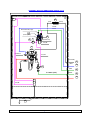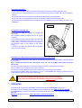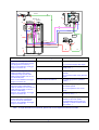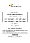
1
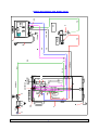
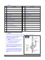
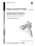
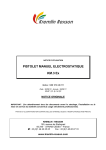
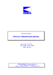
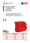
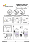
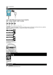
INSTRUCTION MANUAL ISO BUBBLE II Manual : 0805 573.173.112 Date : 19/05/08 - Supersede : 21/01/08 Modif : + § 8 (Breakdowns and solutions) KREMLIN REXSON : 150, avenue de Stalingrad 93 245 - STAINS CEDEX - FRANCE Téléphone : 33 (0)1 49 40 25 25 Fax : 33 (0)1 48 26 07 16 INSTRUCTION MANUAL ISO BUBBLE II SUMMARY 1. EC DECLARATION OF CONFORMITY ....................................................................................................2 2. GENERAL SAFETY INSTRUCTIONS .......................................................................................................2 3. DESCRIPTION ...........................................................................................................................................4 4. OPERATING PRINCIPLE .......................................................................................................................... 4 5. TECHNICAL FEATURES...........................................................................................................................4 6. INSTALLATION .........................................................................................................................................5 7. OPERATING ............................................................................................................................................10 8. BREAKDOWNS AND SOLUTIONS ........................................................................................................11 9. PNEUMATIC DIAGRAM .......................................................................................................................... 13 SPARE PARTS : KREMLIN REXSON Equipments for water-based material applications (doc. 573.304.050) Iso bubble II (doc. 573.305.050) Page 1 Manual : 573.173.112 Dear Customer, We thank you very much for purchasing your new water-based bubble designed for water-based product electrostatic applications. Special care has been taken during all designing and manufacturing process to make sure your investment will provide full satisfaction. However, to get the best result, safe and efficient operation of your equipment, we advice you to read and make yourself familiar with this instruction and service manual. 1. EC DECLARATION OF CONFORMITY The manufacturer : KREMLIN REXSON with assets of 6 720 000 euros Head office : 150, avenue de Stalingrad – 93 245 - STAINS CEDEX - FRANCE Tel. 33 (0)1 49 40 25 25 - Fax : 33 (0)1 48 26 07 16 Herewith declares that : water-based bubble, is in conformity with : - Machinery directive (Directive 98/37/EEC) and with na tional implementing legislation, - Certificate of conformity for non-flammable water-based paint electrostatic spreading installation. Test report : INERIS n° 90691/07 European Standard : EN 50059 : 1993 Established in Stains, on January 14th 2008, Daniel TRAGUS President 2. GENERAL SAFETY INSTRUCTIONS WARNING : Any misuse of the equipment or accessories can damage them, result in serious body injury, fire or explosion hazard and reduce the equipment working life. Read, understand and comply with the safety instructions hereafter. The personnel involved in operating and servicing this equipment must be aware of all safety requirements stated in this manual. The workshop supervisor must be certain that the personnel has perfectly understood the safety instructions and complies with them. Read all instruction manuals as well as the tags of the equipments before operating the equipment. Refer to local safety instructions and comply with them. INSTALLATION REQUIREMENTS A typical installation designed to spray non-flammable conductive material (waterbased paints) must not be used to handle flammable material (solvent-based paints). Never use flammable cleaning solvents. Using the water-based bubble for flammable materials (solvent-based paints) may create unsafe conditions such as : explosion, fire, electric shock hazard and serious body injury for the personnel. KREMLIN REXSON Page 2 Manual : 573.173.112 Use the equipment only in a properly ventilated area to maximize health care. Never stock paints and solvents in the spray area. Always close the pots and the tins. Always keep the spray area clean and free from debris (solvent, rags,…). Read paint and solvent manufacturer's technical instructions. Spraying of some materials may result in hazardous working conditions. To protect the operator, respirator mask and hand cream and glasses are required (Refer to chapter "Safety equipment" of KREMLIN selection guide). EQUIPMENT REQUIREMENTS The operating pressures of these equipments are particularly high. Consequently, some precautions must be taken in order to prevent from accidents and from unsafe working conditions. Never exceed the components maximum working pressure of the equipment. BUBBLE Ground the bubble. HOSES Do not use hoses with a maximum burst-proof pressure less than four times the maximum service pressure of the pump (see data sheet). Be certain the hoses are not crimped, leaking and not unrolled. Be certain hoses are in good conditions and showing no evidence of damage. Use only insulating air hoses to connect the equipments located inside the bubble. Use only a specific fluid hose to connect the pump to the gun. Use only a KREMLIN specific air hose to connect the STD9B box to the gun. All fittings must be tight and in good condition. PUMP Remove the earth-cable from the pump. Do not use any product or solvent incompatible with the pump components. Use the appropriate solvent for the material being sprayed to increase the equipment working life. GUN Never wipe the end of the tip with the fingers. Always depressurize air and hoses before carrying out any servicing on the gun. Never point the spray gun at anyone or at any part of the body. MAINTENANCE REQUIREMENTS Never modify these equipments. Check them daily, keep them in a good condition and replace the worn parts only with KREMLIN parts. Before cleaning or removing components of the equipment, it is compulsory : 1 - to switch off the equipment, 2 - to shut off the compressed air supply, 3 - to open the pump drain valve, 4 - to point the gun into an appropriate waste receptacle and press the gun trigger to depressurize the system. KREMLIN REXSON Page 3 Manual : 573.173.112 3. DESCRIPTION The bubble is designed to receive the coating material equipment for non-flammable water-based materials. This equipment may be composed of : either an airspray pneumatic pump, either an AIRMIX pump, either a pressure tank (30 liters / 8 US gal maxi). The gun may be : a manual gun, model K3H2O, or a standard automatic gun mounted on an insulating support. The voltage from 0 to 8 V given by the STD9B box is sent to the HV generator located inside the bubble. All parts located inside the bubble are negatively charged as is the voltage of the HV generator. The paint is then charged and sent to the gun. 4. OPERATING PRINCIPLE The water-based paints are highly conductive materials with very low resistivity. When operating the gun, all parts located inside the bubble are negatively charged. When the gun trigger is released or the bubble door opened, the electrical charge accumulated by the pump or the tank is automatically evacuated through the ground by means of the ground connection single acting cylinder. 5. TECHNICAL FEATURES Stickers on the Iso bubble II ENCEINTE ISOSTATIC CE Stains France DE PROTECTION POUR MODELE MODEL : ENCEINTE HYDRODILUABLE II REFERENCE : 148 260 100 TENSION D'ENTREE INPUT VOLTAGE : 8 V DC PUISSANCE POWER SUPPLY : 5.2 W INTENSITE DE SORTIE OUTPUT INTENSITY : 100 µA PEINTURES HYDROSOLUBLES WATER-BASED ISOSTATIC BUBBLE RECINTO ISOSTATICO DE PROTECCION PARA PINTURAS HIDROSOLUBLES NE PAS UTILISER DE PEINTURES SOLVANTEES DO NOT USE SOLVENT BASED MATERIALS NO UTILIZAR PINTURAS CON DISOLVENTES TENSION DE SORTIE MAXIMUM : 50 kV MAXIMUM OUTPUT VOLTAGE NE PAS UTILISER DE SOLVANTS PRESSION AIR AIR PRESSURE : 6 BAR : 87 PSI DO NOT USE FLAMMABLE SOLVENTS TO CLEAN THE ISO-BUBBLE CONFORME CONFORMITY : EN 50059 INERIS 90691/07 INFLAMABLES PARA LA LIMPIEZA KREMLIN REXSON INFLAMMABLES POUR LE NETTOYAGE Page 4 NO EMPEAR DISOLVENTES Manual : 573.173.112 Material White polyethylene Total height (mm) 1453 External diameter (upper part/lower part) (mm) 721 / 700 Internal height (mm) 1000 Internal diameter (mm) 680 Weight (kg) 30 The ISO BUBBLE II commercialized consists of : - the bubble with or without the generator barrel, - some fittings and hoses to supply air to the bubble and the STD9 B box. CAUTION : The pumping system, the STD9 B box, the gun and the insulating fluid hose are not included in the water-based bubble. 6. INSTALLATION TYPICAL INSTALLATION (EXAMPLE WITH MANUAL GUN) 4 1- Bubble 2- Pump 3- Fluid container 4- STD9B box 5- K3 H2O gun 18- Insulating specific fluid hose 2 1 3 5 18 A safe electrostatic system installation requires compliance with all applicable safety standards and requirements outlined in this manual. It must not be placed near an installation for water-based materials. Any improper installation or misuse of the electrostatic coating system can cause serious body injury, fire or explosion or electric shock hazard. The bubble must be inspected frequently and cleaned (inside and outside) to keep it free of coating material deposits. Install the coating material supply equipment (pump or pressure tank) inside bubble. Use only metallic container for supplying pump with material. Connect all the hoses. KREMLIN REXSON Page 5 Manual : 573.173.112 6 KREMLIN REXSON 1 7 23 24 8 16 30 12 17 ISO BUBBLE 9 2 21 HT 10 11 +8 V 26+27+33 29 generator 6 bar max Page 6 + 8 V max D. 8x10 D. 10 D. 4x6 20 15 13 25 19 18 K3 H2O 5 22 STD9 B + 8 V max 1,5 bar mini 4 28 14 32 BUBBLE WITH MANUAL GUN, MODEL K3H2O Manual : 573.173.112 18 ATX or A25 D.10 + 8V 30 21 HT g enerat or ISO BUBBL E 6 8 1 23 7 9 6 bar max 29 + 8 V max 20 D.4x6 D.8x10 15 13 25 19 4 1,5 bar m in i + 8 V m ax STD9B 14 ATX o r A25 32 5 BUBBLE WITH STANDARD AUTOMATIC GUN, MODEL ATX NOTA : The ATX guns must be mounted on an insulating support. KREMLIN REXSON Page 7 Manual : 573.173.112 Captions : Ind. Description Ind. Description 1 Bubble 18 Gun fluid supply hose (insulating specific hose) 2 Pump 19 Wire cable (230 V + earth) or (115V + earth) 4 STD9B box 20 Insulating air hose (pump), 10 / 3/8 dia , 3/8 NPS 5 Gun 21 Ground connection single acting cylinder 6 Main air supply 22 Safety warning sign 7 Air and water separator 23 Earth cable 8 Main air valve 24 Door switch 9 Main air regulator 25 Connecting air pilot line (4x6) 10 Air supply shut off valve 26 Cell 11 Air regulator (fluid pressure) 27 Air flow rate adjuster 12 Spraying air regulator 28 Flow switch 13 Flow switch air supply hose (8x10 / 5/16 x 3/8)) 29 Ex generator (with cable ind. 15) 14 Gun air supply hose (conductor) 8 / 5/16 dia , hoses 1/4 NPS 30 Air intake assembly 15 Low voltage cable of the BG Ex (+ 8 V max) 32 Air regulator with gauge (STD9B box air outlet) 16 Fluid filter 33 Air regulator (presetting carried out in the factory) 17 Drain valve ASSEMBLY Install the coating material supply equipment (pump or pressure tank) inside the bubble. Connect the "air intake" assembly (30) and all the hoses supplied with the bubble. 2 : pump air inlet connection 20 : Bubble air supply hose (insulating hose 10 / 3/8 dia) 26+27 : air hose (2,7x4) yellow fitting of the assembly (flow adjuster and cell) 35 : plug or fitting to be mounted Fix the 'air intake' assembly (30) to the pump air equipment. Screw the fitting (M 3/8 BSP) in the pump air supply valve (refer to diagram with pump, model 10-14 - following page) (*) : A plug and a fitting are supplied with the 'air intake' assembly. Screw the plug in the cross or install instead of it the fitting to get an additional air supply, if necessary (eg : supply a pneumatic agitator). Ind. 30 2 M 3/8 BSP 26+27 T 2,7x4 35 M 3/8 NPS M 1/4 NPS D. 10 mm 20 KREMLIN REXSON Page 8 Manual : 573.173.112 ASSEMBLY WITH AN AIRMIX PUMP, MODEL 10-14 T 2,7x4 24 1 29 (+ 8 V) (HT) T 8x10 T 4x6 Grossisseur 4x6 (rouge) 27 (raccord jaune) 26 33 (raccord vert) T 2,7x4 2 M1/4-T8x10 T 2,7x4 (+ 8 V max) T 8x10 30 D. 10mm (3/8") 15 13 T 4x6 25 P=6 bar 20 18 21 T 2,7x4 23 KREMLIN REXSON Page 9 Manual : 573.173.112 Connecting the hoses : - the air hose (20) between the wall mounting air regulator (9) and the air intake assembly (30). - the air hose ( 2,7x4) between the air intake assembly (30) and the yellow fitting of the assembly (26+27). - the specific fluid hose (18) between the pump fluid outlet and the gun (5) fluid inlet. - the air hose (13) ( 8x10) between the pump air regulator (12) and the STD9 B box inlet. - the air hose (25) ( 4x6) between the red fitting of the flow adjuster (27) and the piloting air outlet on the STD9B box. Ind. 32 Air regulator assembly (32) : An air regulator fiitted with a gauge is supplied with the bubble. The regulator enables to adjust the gun air supply pressure. The whole is mounted at the air outlet of the STD 9 B power supply (upstream of the hose, ind. 14). The hose (10 cm / 0.33 ft long) makes the assembly of the regulator easier at the bottom of the power supply. Connect the air hose (14) between the air regulator (32) and the gun air inlet. Assembly of the Ex generator barrel (29) and connection of the cables If the bubble is not equipped of origin with an Ex generator barrel, you must assemble it inside the bubble and connect it. Nota : The EX generator barrel is fitted with a 6 m / 19.7 ft low voltage cable which cannot be taken apart. Place the generator barrel (29) on the support designed for that purpose (upper cross-link). Fix it by means of the 2 flanges, the screws and the nuts. Connect the HV cable between the generator barrel (29) and the pump earth terminal. Connect the low voltage cable (15), length 6 m / 19.7 ft , to the STD9B power supply (4) inserting the end of that cable through one of the cups of the bubble. Ground the bubble earth cable to a real earth connection. The parts located inside the bubble must not be grounded. 7. OPERATING Compressed air supply to the electrostatic coating sys tem must be absolutely dry and clean. To ensure a proper operating of the equipment, an air supply pressure of 6 bar / 87 psi is required. It is compulsory to connect the manual or automatic electrostatic spray gun to a power supply model STD 9 B. Minimum piloting air pressure : from 1,5 to 2 bar / from 21.76 to 29 psi. KREMLIN REXSON Page 10 Manual : 573.173.112 If an automatic spray gun is used, locate an air repartition box between the STD 9 B power supply and the gun. The box manages the separated adjustment of the fan air and atomizing air. Adjust the fluid supply pressure (regulator 11) and the air supply pressure (regulator 32) of the gun to obtain the required fan. Close bubble door. The gun operating depends on the door-switch position. Switch off Installation in operation. Switch on Installation not in operation. Do not open the door of the bubble during the operating of the gun. Wait for 3 seconds between the stopping of the gun and the opening of the bubble door to evacuate the electrical charge of the parts located inside the bubble. An air regulator (33), located in the bubble, sends air to increase the single acting cylinder coming down and the evacuation of the charge during the stop of the installation. A preset of the regulator is carried out in the factory. If the regulator should happen to go wrong, unscrew completely the adjustment knob, screw by 3 or 4 turns and lock it. The pressure delivered by the regulator must be lower to the pressure applied during the ascent of the single acting cylinder. 8. BREAKDOWNS AND SOLUTIONS Diagnosis during the lack of electrostatic effect on a water-based paint application installation. No electrostatic effect : You can observe the loss of electrostatic effect when using the gun : The red led of the power supply is switched off or slightly switched on, The parts painted do not have by-pass effect, No electric field near the gun electrode. If you notice these troubles, the components of the installation (power supply, HV generator, bubble, hose, gun) installation constitutive components can be involved. If only the lack of by-pass is noticed, you must check the following elements : Grounding of the parts to be painted. Gun spraying air pressure. Previous checkings : Before checking if there is a breakdown : Check the fuse of the power supply Check the condition and the connection of the HV generator cables, Check there is no dirt and trace of damp outside and inside the bubble, Check there is no leak coming from the fluid hose, Make sure there is no leak coming from the gun cartridge and the inside of the aircap is perfectly clean. Find the defective component : If the previous checkings can not explain the cause of the breakdown, follow the instruction described in the chart hereafter : KREMLIN REXSON Page 11 Manual : 573.173.112 STD9 B 4 6 bar max 6 7 8 28 9 19 26+27+33 29 generator 24 20 ISO BUBBLE HT 12 30 2 +8V 32 11 25 10 13 1,5 bar mini + 8 V max 15 16 22 1 17 K3 H2O D. 10 D. 8x10 D. 4x6 5 + 8 V max 21 23 Operations 18 Checkings 14 Diagnosis / solutions Disconnect the HV generator supply cable (ind. 15) at STD power supply level (Plug DIN 3 connectors). Swich on the installation and trigger the gun to consume air. The red led switches on The power supply operates. The red led does not switch on Check the power supply (fuse, supply card,…). Disconnect the HV generator outlet cable (mounted on the pump). Install temporarily the end of the cable inside the bubble over 15 cm from the metal parts. Swich on the installation and trigger the gun to consume air. The red led switches on The power supply and the generator operate. The red led does not switch on Check the generator (oscillator, cabling,…). Disconnect the fluid hose (ind. 18) at pump level and fix it temporarily inside the bubble over 15 cm from the metal parts (be careful you do not make the bubble dirty). Switch on the installation and trigger the gun to consume air. The red led switches on The power supply, the generator and the bubble operate. The red led does not switch on Check the bubble (dampness, jack, grounding, timing,...). Disconnect the fluid hose (ind. 18) at the gun level and fix it temporarily over 15 cm from the metal parts. Switch on the installation and trigger the gun to consume air. The red led switches on The power supply, the generator, the bubble and the hose operate. Connect the supply cable again. Connect the cable of the generator again.. Connect again the hose on the pump. Disassemble and check the gun (cartridge, material inside the barrel air-conduits,…). Nota : To repair the different components, please refer to the respective instruction manuals. KREMLIN REXSON Page 12 Manual : 573.173.112 32 OUT 28 IN 4 D . 8 mm (5/16 " ) T 4x6 T 8x10 Page 13 25 18 13 1 2 P = 1,5/2 bar mini 12 23 21 11 27 2 26 D. 1 0 mm (3/8") 30 33 20 P = 6 bar AC T 2,7x4 KREMLIN REXSON 1 3 24 T 2,7x4 14 5 9. PNEUMATIC DIAGRAM Manual : 573.173.112