1
Fiat Group S.p.A.
TEACHING GUIDE
M40 ROBOTISED GEARBOX
Training Academy
ROBOTIZED GEARBOX
M40
1 / 47
© 2007 Fiat Group S.p.A. – All rights reserved
Fiat Group S.p.A
TEACHING GUIDE
M40 ROBOTISED GEARBOX
Training Academy
DOCUMENTATION AMENDMENTS/UPDATES
Date
Contact
Filename
Description of the amendment
© 2007 – Fiat Group S.p.A.
All rights reserved. The circulation and reproduction of all or part of this guide by any
means is prohibited.
Fiat cannot be held specifically liable for involuntary errors or omissions during
material processing.
The information in this guide is subject to continuous updating. Fiat Group S.p.A.
accepts no responsibility for consequences arising from the use of out-of-date
information.
This publication is for training purposes only.
For up-do-date and comprehensive technical information for service purposes refer to
the service manual and service information regarding the vehicle model in question.
© 2007 Fiat Group S.p.A. – All rights reserved
2 / 47
Fiat Group S.p.A.
TEACHING GUIDE
M40 ROBOTISED GEARBOX
Training Academy
CONTENTS
1. INTRODUCTION ........................................................................................................................................ 4
1.1 INTRODUCTION ....................................................................................................................................... 4
1.2 GENERAL OPERATING FEATURES........................................................................................................ 4
2. SPECIFICATIONS ................................................................................................................................... 10
2.1 GEARBOX LAYOUT................................................................................................................................ 10
2.2 ELECTROHYDRAULIC KIT COMPONENTS.......................................................................................... 11
3. OPERATING STRATEGIES .................................................................................................................... 23
3.1 OPERATION OF THE SYSTEM .............................................................................................................. 23
3.2 SELF-CALIBRATION .............................................................................................................................. 26
4. FUNCTIONAL INTERACTION WITH OTHER SYSTEMS........................................................................ 33
4.1 INTERACTION WITH ENGINE MANAGEMENT...................................................................................... 33
4.2 INTERACTION WITH CRUISE CONTROL .............................................................................................. 33
4.3 ABS INTERACTION ................................................................................................................................ 33
4.4 ESP-ASR-MSR INTERACTION............................................................................................................... 33
5. SAFETY FUNCTIONS IN THE CASE OF FAILURE................................................................................ 34
5.1 INCORRECT COMMANDS .................................................................................................................... 34
5.2 VISUAL/ACOUSTIC INFORMATION FOR THE DRIVER ........................................................................ 34
6. MULTISTABLE LEVER ........................................................................................................................... 36
6.1 DESCRIPTION........................................................................................................................................ 36
6.2 KEY ON (+15).......................................................................................................................................... 36
6.3 SYSTEM BEHAVIOUR WITH ENGINE STARTED AND/OR VEHICLE MOVING..................................... 37
6.4 GEAR CHANGE WITH VEHICLE MOVING ............................................................................................. 38
6.5 REQUEST FOR NEUTRAL WITH VEHICLE MOVING............................................................................ 40
6.6 REQUEST FOR REVERSE WITH VEHICLE MOVING ............................................................................ 40
6.7 SYSTEM SAFETY FEATURES ............................................................................................................... 41
7. SPECIFICATIONS ................................................................................................................................... 42
7.1 GEAR RATIOS ........................................................................................................................................ 42
7.2 CLUTCH.................................................................................................................................................. 43
7.3 FLUIDS AND LUBRICANTS .................................................................................................................... 43
7.4 ROBOTISED GEARBOX CONTROL UNIT.............................................................................................. 43
7.5 SENSOR/ACTUATOR ELECTRICAL SPECIFICATIONS........................................................................ 44
3 / 47
© 2007 Fiat Group S.p.A. – All rights reserved
Fiat Group S.p.A
TEACHING GUIDE
M40 ROBOTISED GEARBOX
Training Academy
1. INTRODUCTION
1.1 INTRODUCTION
The concept of a transmission system with robotised control (MTA: Mechanical Transmission
Automatized) for the M40 gearbox pursues the same aim as in previous versions, i.e. to improve the
performance of the manual transmission components. With this system, the driver need not control the
clutch pedal and the gear lever but is still able to enjoy the driving satisfaction arising out of direct control
of the transmission.
It also improves driving safety through direct control, which prevents driver errors and incorrect control of
the transmission system, offering the driver a more advanced vehicle interface.
The system basically consists of a manual transmission, with a dry, single plate clutch and manual
gearbox with synchromesh with hydraulic power assistance.
As before, neither the clutch or the gearbox are modified for installation of the hydraulic actuators used to
control clutch travel and gear engagement and selection manoeuvres.
1.2 GENERAL OPERATING FEATURES
The MAT system for the M40 offers the following features:
• Improves the performance of the manual mechanical transmission components.
• Saves the driver having to control the clutch pedal and the conventional gear lever.
• Improves safe driving by means of a control that prevents driver errors and the incorrect operation of
the transmission system.
• It is a hydraulic power assistance system for the gearbox and the clutch that makes it possible to
maintain all the advantages of a dry clutch and a manual gearbox (weight, strength and reliability, low
energy consumption).
• It is simple to use and makes driving less tiring, especially town driving.
• It ensures comfortable or sports gear changes due to advanced power assistance strategies.
• There is no clutch pedal in the passenger compartment and the gear lever has been replaced with
"Up/Down/Neutral/Reverse" controls on a joystick on the centre tunnel.
• Automatic management of the gearbox can be enabled (by the driver) in AUTO mode with two different
modes (ECO/NORMAL).
There are two system operating modes for the robotized gearbox:
• SEMIAUTOMATIC MODE (MANUAL): the driver engages the gears using the lever located on the
tunnel
• AUTOMATIC MODE (AUTO): the electronic system is responsible for shifting the gears in accordance
with two strategies, the first designed for driving comfort (NORMAL), the latter with the aim of shifting
gears at higher speeds to allow the vehicle to be driven up steep roads with ease, whatever the load
(UP).
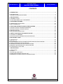
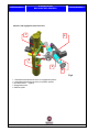
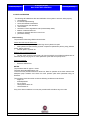
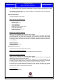
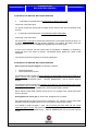
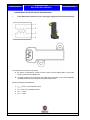
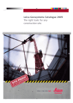
General diagram showing main robotized gearbox system components
© 2007 Fiat Group S.p.A. – All rights reserved
4 / 47
Fiat Group S.p.A.
TEACHING GUIDE
M40 ROBOTISED GEARBOX
Training Academy
1.TCU (Transmission Control
Unit)
2. Electrohydraulic unit with
electric pump
3. Gear display and panel
4. “UP” button
5. Brake pedal (with dual
switch)
6. Gear and Auto mode
selector lever
7. Accelerator pedal (Drive
by Wire)
8. Yaw sensor (Yaw Rate
node)
The power assisted system consists of an electrohydraulic unit (2) fitted directly on the gearbox casing
which manages the following gearbox movements by means of two actuators:
• gear selection and engagement manoeuvre
• Control of clutch opening.
The electrohydraulic unit is controlled by four solenoid valves (for which an electric pump and an
accumulator provide the required hydraulic power).
Having identified the driver's requests from the position of the lever, an electronic control unit (1) manages
the gear change independently, controlling the clutch, gearbox and engine torque directly.
The synergy between the gearbox and the engine improves the performance of the system considerably
and frees the driver from any need to synchronize clutch-accelerator movements during gear changes
which can be carried out with the accelerator fully depressed.
The system inhibits requests for incorrect gear changes and prevents the engine from cutting out.
In terms of driving assistance the system also ensures the immediate availability of first gear when the
vehicle stops and the automatic changing up through the gears in the case of strong deceleration.
The indication of the gear engaged is shown on a display in the instrument panel, in the same way as the
signalling of faults or critical driving conditions for the vehicle or the transmission components with a
series of warning or failure messages for the system together with the general failure or transmission
failure warning lights.
General system concepts
1. Position of gears in gearbox grille and solenoid activations
5 / 47
© 2007 Fiat Group S.p.A. – All rights reserved
TEACHING GUIDE
M40 ROBOTISED GEARBOX
Fiat Group S.p.A
2.
3.
4.
5.
6.
7.
Training Academy
Clutch closed, kiss point, transmissibility and transmissibility index
Wake up
Clutch shifts for overspeed and underspeed
Limphome
Retry
Power latch
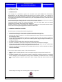
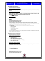
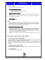
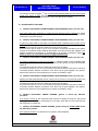
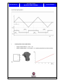
Position of gears in gearbox grille and solenoid activations:
Griglia DUCATO
800
700
innesto
600
500
400
300
200
200
300
400
500
600
selezione
© 2007 Fiat Group S.p.A. – All rights reserved
6 / 47
700
800
TEACHING GUIDE
M40 ROBOTISED GEARBOX
Fiat Group S.p.A.
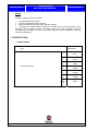
Gear disengagement for all
gear changes
N>1
Training Academy
EV1
EV2
ON
ON
ON
ON
ON
1>2
ON
2>3
ON
4>5
N>R
ON
1>R
ON
6>5
ON
ON
ON
4>3
ON
Note: return to stable neutral position is carried out by the
selection counterspring
2>1
ON
ON
ON
3>2
ON
ON
ON
5>4
ON
ON
ON
5>6
ON
ON
ON
3>4
EV3
ON
ON
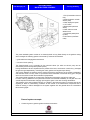
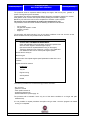
Closed clutch position :
The closed clutch position is calculated with the clutch closed and clutch solenoid off (with the
vehicle in motion). This value is used, together with the kiss point, to calculate the clutch position
reference when the clutch is open during a gearshift or when the vehicle is it a standstill with the
engine running and gear engaged (awaiting take-off with clutch open during regulation).
Its value varies according to clutch wear (the value increases as wear increases)
Closed clutch
Kiss Point
Opened clutch
0
Delta Kiss
Kiss point:
The Kiss Point is calculated after the engine has been started. During the calculation of the kiss
point the clutch is brought closer (the gearbox must be in neutral) and the clutch position where the
clutch begins to turn and therefore to transmit torque is recorded. The value of this position is
subtracted from the closed clutch position to give the Kiss Point value. Its value varies according to
clutch wear (the value decreases as the clutch increases)
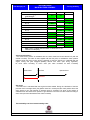
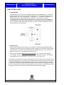
Transmissibility and clutch transmissibility index :
7 / 47
© 2007 Fiat Group S.p.A. – All rights reserved
Fiat Group S.p.A
TEACHING GUIDE
M40 ROBOTISED GEARBOX
Training Academy
This is an non-dimensional value linked to clutch wear that is calculated during take-off. It is used to
adjust the opening and closing of the clutch during gear changes and is also used to adjust clutch
closing during take off. . If this value is incorrect it leads to slipping or sudden closing of the clutch
during gear changes or during take off. Its calculation is influenced by the take off (take off using the
brake pedal should be avoided for example)
Clutch
Torque
[Nm]
Max engine
torque [Nm]
Transmissibility
margin
Maximum
Minimum
Closed
clutch
Kiss
point
Wake up
A system function that allows the pressure in the hydraulic circuit to be increased before the
instrument panel is switched on; it is activated when the door is opened When the door is opened, the
TCU wakes up and the pump is activated if hydraulic circuit pressure is insufficient.
Pump inactivation is associated with sufficient pressure level in the circuit (the pressure must be lower
than the pump activation pressure threshold for the pump to be activated) or may be due to a fault (e.g.
door switch operating failure, a relay or pump fuse fault etc.).
Gearshifts due to overspeed:
Overspeed gear shifts take place when the MTA system automatically upshifts in manual mode.
This occurs when the engine rpm reaches a given level (approximately 3800 rpm). At this point, the
gear shift takes place automatically.
Gearshifts due to overspeed:
Gearshifts taken place due to underspeed when the MTA automatically carries out one or more
downshifts (e.g. from 5th to 4th to 3rd) to prevent the engine running under speed and stalling. The
vehicle may be braked without requesting any downshift. The system shifts down through the gear so
that first is engaged when the vehicle stops.
Limp Home
Limp Home mode is a reduced driving mode that is imposed when there is a fault in the system. This
mode is only certain faults (for example a fault with the engagement position sensor) and it is only
possible to engage the 1st, 2nd and reverse gears. If the MTA system is in limp home mode, system
performance is obviously lower than when operating normally (gear shifts are slower).
© 2007 Fiat Group S.p.A. – All rights reserved
8 / 47
Fiat Group S.p.A.
TEACHING GUIDE
M40 ROBOTISED GEARBOX
Training Academy
Retry
Retry is a strategy that attempts to engage a gear that was requested previously but could not be
engaged, possibly due to a problem. During the retry manoeuvre, the system makes a second
engagement request (from neutral) once the impossibility of gear engagement has been established
and engages the requested gear + 1 if it cannot engage the gear at the second attempt (for example:
in a gear shift 2 > 3, if third gear is not engaged even after a retry, the system will engage 4th).
There are some specific cases:
if first gear is requested with the vehicle at a standstill, the gearbox will shift to neutral if the retry fails
if reverse is requested with the vehicle at a standstill, the gearbox will shift to neutral if the retry fails
Power latch
Power latch is the TCU deactivation procedure. This procedure is implemented when the panel is
turned off (+15 off) under certain conditions:
No gear change in course
Engine speed less than 400 rpm
Clutch speed 0
Clutch closed
Ignition signal +15 at 0
If these conditions are present, the deactivation procedure starts one second after K15 During this
procedure, the TCU is self-powered via the +30 power supply (see pinout) and saves a set of
parameters (adaptive clutch parameters, system counters such as gear shift counters etc.) in the flash
memory.
The parameters are saved only if the gear positions in the gearbox grille (learnt during gearbox grille
self-calibration) are plausible.
If the TCU power supply at +30 is not present, the power latch procedure cannot be run (with +15 off,
the TCU goes off permanently).
The power latch procedure lasts for approximately 5 seconds.
9 / 47
© 2007 Fiat Group S.p.A. – All rights reserved
Fiat Group S.p.A
TEACHING GUIDE
M40 ROBOTISED GEARBOX
Training Academy
2. SPECIFICATIONS
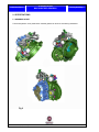
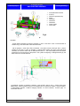
2.1 GEARBOX LAYOUT
The electrohydraulic unit is positioned on the M40 gearbox as shown in the following illustrations.
Fig 2
© 2007 Fiat Group S.p.A. – All rights reserved
10 / 47
Fiat Group S.p.A.
TEACHING GUIDE
M40 ROBOTISED GEARBOX
Training Academy
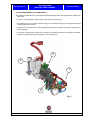
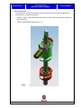
2.2 ELECTROHYDRAULIC KIT COMPONENTS
The hydraulic kit takes the form of a single part positioned directly on the manual gearbox. It contain three
main parts.
• a power unit comprising the electric pump, accumulator and reservoir (1);
• the solenoid valve unit converts hydraulic energy into mechanical energy by the engagement pistons
interfacing with drive shaft (2);
•
the gear control mechanical unit which interfaces directly with the gearbox through the opening in the
actual casing (3);
• A hydraulic unit made up of a CSC (clutch actuator), CS SPEED fluid reservoir (hydraulic transmission
actuator) and DOT 4 fluid reservoir (hydraulic clutch actuation)(4)
3
4
1
2
Fig. 3
11 / 47
© 2007 Fiat Group S.p.A. – All rights reserved
TEACHING GUIDE
M40 ROBOTISED GEARBOX
Fiat Group S.p.A
Training Academy
Power unit
The power unit supplies hydraulic energy to operate gear engagement/selection and also the clutch cylinder. The
unit includes electric pump (C) and fluid reservoir (B). A semi-rigid high pressure pipe also connects the
accumulator to the solenoid unit while a preformed low pressure rubber hose connects the valve unit to the reservoir.
b
a
c
Fig. 4
A. High pressure oil pump motor assembly
B. Pre-loaded nitrogen accumulator
C. System pressure sensor
The system operates at a line pressure that varies between 36.5 and 46 bar in normal conditions. In
Recovery condition, the system can work at maximum at a pressure of 75 bar.
The electric pump is activated when the pressure goes below 36.5 bar and is deactivated when the circuit
pressure reaches 46 bar.
Technical specifications:
• Line pressure between 36 and 46 bars
• Service temperature between -30° C and + 105 ° C
• Start-up possible up to a temperature of -30° C
• Pump capacity is >0,81 l/min at 45 bar, 3450 rpm and fluid at 60 °C
• The accumulator volume is 250 cm3, preloaded to 24 bars at 20 °C
© 2007 Fiat Group S.p.A. – All rights reserved
12 / 47
Fiat Group S.p.A.
TEACHING GUIDE
M40 ROBOTISED GEARBOX
Training Academy
Solenoid unit
This system performs the following functions:
• Controls and manages the position of the clutch
• Controls and manages gear selection and engagement.
5
3
1
Fig 5
2
4
The following components are used for these controls (Fig. 5).
1. Proportional flow solenoid for controlling the clutch (EV0)
2. Proportional pressure solenoid valve for even gear engagement (R - 2 - 4 - 6) (EV2)
3. Proportional pressure solenoid for odd gear engagement (1 - 3 - 5). (EV1)
4. Proportional flow solenoid for range selection (EV3)
5. Mechanical selection and engagement unit (Fig. 6).
13 / 47
© 2007 Fiat Group S.p.A. – All rights reserved
TEACHING GUIDE
M40 ROBOTISED GEARBOX
Fiat Group S.p.A
Training Academy
Selection and engagement mechanical unit
1
2
5
3
4
Fig 6
1. Linear differential transformer sensor for engagement position. .
2. Linear differential transformer sensor for selection position. .
3. Kit interface lever – gearbox
4. Engagement piston
5. Selection piston
© 2007 Fiat Group S.p.A. – All rights reserved
14 / 47
Fiat Group S.p.A.
TEACHING GUIDE
M40 ROBOTISED GEARBOX
Training Academy
Clutch actuator
1
fig 7
1. Master-slave unit
Master-slave system
The Master-Slave system (fig 7 and fig 8) is positioned under the CS SPEED fluid reservoir and is
made up of a cylinder inside which a piston moves to form three chambers: in the first chamber the
pressurised fluid arrives from the hydraulic unit via solenoid EV0; the second and third chambers
come into contact with the flow of fluid DOT4 which, depending on the thrust the fluid receives from
the first chamber, produces the thrust on the clutch CSC actuator (slave). The advantage of
adopting this solution is that the same CSC as fitted to the manual gearbox may used
15 / 47
© 2007 Fiat Group S.p.A. – All rights reserved
Fiat Group S.p.A
TEACHING GUIDE
M40 ROBOTISED GEARBOX
Training Academy
1.
2.
3.
4.
5.
6.
7.
8.
9.
Fluid inlet/outlet from EV0
In DOT4
Out DOT4 (towards CSC)
Piston
Chamber 1
Chamber 2
Chamber 3
Clutch closed
Clutch open
Fig 8
Operation:
- at rest (without pressure from EV0 in Chamber 1), INDOT4 and OUTDOT4 are in communication in
chamber 3 (7), so that chamber 3 fills with DOT4 fluid.
- with oil pressure > 0 bar due to EV0 in Chamber 1, the piston moves to the right: INDOT4 goes to
chamber 2 and OUTDOT4 goes to chamber 3; nothing further enters from INDOT4 while the thrust
necessary to move the clutch CSC is obtained from OUTDOT4 . The clutch displacement is therefore
proportional to the movement of the piston in the cylinder. Everything is managed directly by the
MTA control unit via solenoid EV0.
1.Crankshaft; 2.engine; 3.flywheel; 4.gearbox; 5.Csc; 6.DOT4 pipe to Csc; 7. DOT4 output from
Master-slave; 8.clutch position sensor; 9.CS speed fluid input from EV0 actuator; 10.EV0 actuator;
11.Intermediate chamber; 12.DOT4 charging chamber; 13. DOT4 reservoir; 14.DOT4 pipe; 15.
Connection with Csc.
© 2007 Fiat Group S.p.A. – All rights reserved
16 / 47
TEACHING GUIDE
M40 ROBOTISED GEARBOX
Fiat Group S.p.A.
Training Academy
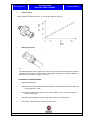
Gear selector shaft
The gear selector chooses the appropriate gearbox gear and then manages gear engagement and
range selection. It is made up as follows:
•
Selection - shifter – shaft with threaded hole in head for coupling and fastening with the hydraulic kit
(fig 9 and fig10:b)
•
Gearbox centring/fastening flange (fig 10: a,c)
Fig. 9
-{}-
17 / 47
© 2007 Fiat Group S.p.A. – All rights reserved
TEACHING GUIDE
M40 ROBOTISED GEARBOX
Fiat Group S.p.A
Training Academy
b
a
Fig. 10
-{}-
c
Gear selector operating principle
The engagement actuator, made up of a double-acting piston, is pushed one way or the other at the
required rate due to the balanced action of proportional pressure valves EV1 and EV2, which are
powered simultaneously.
The shaft’s rotatory motion (corresponding to gear shifts in the same range or shifting from even to
odd gears or viceversa) is implemented by two simple steps:
•
When EV1 is activated, the hydraulic piston moves linearly in a clockwise direction [odd gears
(R-1-3-5)]
•
When EV2 is activated, the hydraulic piston moves linearly in an anticlockwise direction [even
gears (2-4-6)]
The selector actuator may be described schematically as a single-acting piston. An internal return
spring positioned in the lower part of the selection piston locates it stably in a position corresponding
to the reverse range (top, fig. 11). When a flow from the accumulator towards the actuator is
requested from proportional solenoid EV3, the selection piston moves the gear control lever and shaft
along the shaft centre line towards the 5/6 range (bottom, fig. 11). The spring inside the actuator is
loaded. When a flow is required from the actuator towards the outlet, the spring extends to move the
actuator towards the reverse range.
© 2007 Fiat Group S.p.A. – All rights reserved
18 / 47
Fiat Group S.p.A.
TEACHING GUIDE
M40 ROBOTISED GEARBOX
4
1
Training Academy
1.Camera di carico da EV1
2.Camera di carico da EV2
3.Molla di ritorno del pistone di
selezione
4.Camera di carico da EV3
2
3
Fig. 11
The unit is equipped with a recirculation function for any leaks from the two lipped seals on the
engagement piston or the selection piston. Emerging oil collects at the base of the compartment (visible in
fig. 12) and is taken up into the reservoir by means of the vacuum created in the reservoir by the action of
the pump. At the end of each pump action, pressure inside the compartment is restored to atmospheric
level through a hole located under the engagement position sensor.
1
Fig. 12
1.Draining opening for possible leaks.
19 / 47
© 2007 Fiat Group S.p.A. – All rights reserved
TEACHING GUIDE
M40 ROBOTISED GEARBOX
Fiat Group S.p.A
Training Academy
Electronic control unit
The control unit is located in the passenger compartment, positioned horizontally on the right side
of the pedal unit (driver’s side).
pin
no.
15
N.c.
16
N.c.
Function
1
GND1_PWR-Ground
17
N.c.
2
GND2_PWR-Ground
18
N.c.
3
N.c.
19
4
N.c.
MPXCANH+_COM_OUT (daisy
chain)
5
N.c.
20
N.c.
6
N.c.
21
N.c.
22
N.c.
7
MPXCANL-_COM_OUT (daisy
chain)
23
N.c.
8
N.c.
24
Gear_POS_S1
9
N.c.
25
Gear_POS_P1
10
N.c.
26
Pos 1-GSL0 (A)
11
N.c.
27
KL30 Supply
12
Gear_POS_S2
28
KL15 Key Sense
13
Gear_POS_P2
29
SHIFT1+_OP
14
N.c.
30
N.c.
© 2007 Fiat Group S.p.A. – All rights reserved
20 / 47
Fiat Group S.p.A.
TEACHING GUIDE
M40 ROBOTISED GEARBOX
Training Academy
31
HYDPUMP+_OP-Pump relay
57
N.c.
32
GEAR1+_OP
58
N.c.
33
MPXCANL-_COM_IN
59
34
Shift_POS_P1
SNSGND3-Clutch Position/
Hyd_Press Sensor Gnd
35
Shift_POS_S1
60
N.c.
61
N.c.
36
N.c. (VSO Signal (VEHSPEED)
PREDISPOSIZIONE)
62
N.c.
37
N.c.
63
N.c.
38
CLTSPD+ (Freq)
64
N.c.
39
N.c.
65
SNSGND2
40
Hydraulic Pressure Sensor
(signal)-HYDPRES (A)
66
N.c.
67
Pos 2-GSL1 (A)
41
N.c.
68
Pos 4-GSL3 (A)
42
CRANKREL_OD-Crank
Command (D)
69
Brake Light Switch (A)
43
CLUTCH+_OP
70
N.c.
44
GEAR2+_OP
71
N.c.
45
MPXCANH+_COM_IN
72
N.c.
46
Shift_POS_P2
73
N.c.
47
Shift_POS_S2
74
Pos 3-GSL2 (A)
48
N.c. (RPM Signal (TACHIN)
(Freq) PREDISPOSITION)
75
N.c. (Steering wheel TAP
commands (up/ down)
PREDISPOSITION)
49
SERIAL K
76
(+50) Crank Request (D)
50
CLTSPD- (Freq)
77
UP Switch-AUTOGRPN_ID (D)
51
N.c.
78
Driver Door Status (A)
52
CLUTCHPOS (signal) (A)
53
N.c.
79
54
N.c.
SNSsPL2-Clutch Position
Sensor/ Hyd_Press Supply1
(+5V)
55
N.c.
80
N.c. (Buzzer (Digit)
PREDISPOSITION)
56
N.c.
21 / 47
© 2007 Fiat Group S.p.A. – All rights reserved
Fiat Group S.p.A
TEACHING GUIDE
M40 ROBOTISED GEARBOX
Training Academy
Input signals
The system uses the following signals arriving from other vehicle systems for the operating logics:
•
•
•
•
•
•
CAN)
•
•
specific sensors from the robotized gearbox
clutch rpm sensor (the reading is taken from the main gearbox shaft)
position sensor for: clutch, engagement and selection
Individual signals coming from other vehicle systems.
engine rpm (signal coming from the engine management control unit via the C-CAN)
brake pedal switch (two signals: one discrete - pin 9 vehicle connector, the other via the Cdriver's door open switch (discrete)
key-on (stable position and starting discrete
The following other signals arrive from other systems via the CAN:
•
•
Accelerator pedal position.
engine torque, vehicle speed, engine temperature, etc.
Output signals
The reversing light activation signal is managed by a switch on the gearbox.
User interface
The user interfaces with the system via the following controls:
- accelerator pedal via the CAN from the engine management node
- brake pedal, via two signals: one discrete, the other via the C-CAN
- Gear shift or mode selection request by means of a specific multistable electromechanical lever with
three stable positions (NEUTRAL, REVERSE and TIP) and three unstable positions (UP, DOWN,
AUTOMATIC/MANUAL) via 4 signals that convert the electric signals from 10 Hall effect sensors
located inside the lever (the signals must be read by the control unit as analogue inputs for safety
reasons).
- UP mode (the signal is given by a switch connected directly to the MTA control unit).
The system supports the driver in the following way via the multifunction display:
•
•
•
•
Display of gear engaged (via CAN)
"AUTO" mode selection (via CAN)
Mode in use: “UP" (through the display of the “UP" warning light)
system failures (through a dedicated warning light coming on via the CAN)
•
acoustic signal from the instrument panel buzzer: connected via the CAN, it warns the driver of
a critical vehicle/system situation.
© 2007 Fiat Group S.p.A. – All rights reserved
22 / 47
Fiat Group S.p.A.
TEACHING GUIDE
M40 ROBOTISED GEARBOX
Training Academy
3. OPERATING STRATEGIES
3.1 OPERATION OF THE SYSTEM
Hydraulic circuit pressurization
If the pressure is below the minimum operating level, the pressurization of the hydraulic circuit
takes place in two different ways:
•
- if the driver's door is opened the system automatically pressurizes the hydraulic circuit to
allow a gear change, if requested, without waiting for the circuit to be charged (fixed pump
activation time;
•
with the ignition key on marcia: the system control unit is supplied (and will be until the
ignition key is turned OFF and the vehicle and engine speed is 0).
The system electric pump also receives a power supply to pressurize the system when the
pressure reaches the minimum value of around 36.5 bar.
When the driver turns the ignition key to the unstable cranking position, the MTA control unit:
• allows starting, if the gearbox is in N.
• allows starting only with the brake pedal depressed and the gearbox on “N” if the gearbox is
not in “N”.
Ignition/vehicle starting
The ignition key must be turned: the engine is started with the starting relay controlled directly by
the engine management control unit after the go ahead from the MTA control unit.
There are emergency starting provisions if the battery is not capable of starting the engine, but
the system is correctly pressurized, the vehicle can be pushed (with the clutch open) and when a
sufficient speed is reached, a gear must be engaged using the selector lever; the system engages
the gear that is suitable for the speed of the vehicle in order to start the engine (it is up to the
driver to engage the gear and decide when the vehicle speed is fast enough to start the engine).
Operation with the engine switched off
For safety reasons, any gear change request from the lever (including neutral) is only accepted if
the driver keeps the brake pedal pressed.
Gears available with the engine off are “Reverse”, “1st” and ”N” .
Vehicle take off
The following gears can be engaged, with the engine started and the vehicle stationary, for take
off:
•
1st, 2nd and Reverse; these ratios in these conditions can only be requested through
moving the lever.
It is vital to keep the brake pedal pressed for safety reasons when requesting engagement.
To engage Reverse, in addition to the conditions mentioned above, the vehicle must also be
stationary (gearbox input revs equal to 0).
Vehicle take off is only possible if the driver operates the accelerator pedal (releasing the brake
pedal); at this point, the system gradually engages the clutch to start the vehicle. The driver is
capable of metering the torque transmitted from the clutch by modulating the position of the
accelerator pedal; when the accelerator is released, the clutch should gradually release when a
minimum engine rpm level is reached. When the system detects synchronism between the engine
23 / 47
© 2007 Fiat Group S.p.A. – All rights reserved
Fiat Group S.p.A
TEACHING GUIDE
M40 ROBOTISED GEARBOX
Training Academy
and clutch speeds, it closes the clutch completely. There is a specific clutch engagement map for
each of the three gears enabled during take off. During take off the driver can only request a gear
change when the clutch revs are the same as the engine revs (in other words at the end of the
take off stage); the system is capable of managing the request during this manoeuvre.
Automatic engagement of the clutch downhill with the accelerator pedal released
If the vehicle, with a gear engaged, the accelerator released and the engine, started picks up
speed because it is going downhill, when a pre-set speed is reached, it automatically closes the
clutch to provide the vehicle with engine braking. If the driver presses the accelerator pedal during
this stage, the control of the torque transmitted by the clutch returns to the direct control of the
driver. This automatic engagement of the clutch is interrupted if the vehicle is moving in the
opposite direction to the gear engaged.
Vehicle slowing down
In slowing down conditions, for example with a gear engaged and the accelerator pedal released,
the system automatically releases the clutch to prevent the engine from cutting out when it gets
close to the idle speed. This release takes place at an engine speed that depends on the level of
deceleration and the commands implemented by the driver (brake pressed or not). Whilst slowing
down, if the gear engaged is higher than 2nd, a downshift is controlled automatically. When the
vehicle stops, 1st gear is engaged automatically.
Gear change using lever (semiautomatic operating mode)
With the vehicle moving and the clutch fully engaged, Up or Down requests from the driver via the
gear lever result in a gear change. The requests are only accepted by the system if they are
compatible
with
the
engine
below
revs
and
outside
of
revs
limits.
As a rule, the command at the lever gives rise to an increase or decrease of one gear only,
however, in certain operating conditions the gear increase may be higher than one if requested by
the driver with a double fast command. The gear change manoeuvre carried out by the driver
without releasing the accelerator pedal for an up request, once accepted by the system, is carried
out with an automatic sequence of stages that comply with the driver's behaviour:
• engine torque reduction through a command sent by the system to the engine management
control unit and simultaneous clutch release.
• release, selection and engagement of the new gear, simultaneous to the gear change,
managing the engine control to try and reach the speed of the clutch after the engagement of the
new gear.
• modulated engagement of the clutch and simultaneous gradual return to the max torque that
can be supplied by the engine at the new speed, when the system detects synchronism between
the engine and clutch speeds, controlling the total engagement of the latter.
The management of the three previous phases takes place depending on:
•
estimated performance requested by the driver
•
estimate of the transmission temperature.
A gear change in progress can be interrupted at any time by another request from the driver as
long as it is acceptable (i.e. compatible with the engine below and beyond rev limits).
The actuator control sequences during the gear change are provided with a timeout; in other
words, if the gear change is not successful, it is repeated once starting from neutral, after which a
higher gear than the one requested is engaged.
Automatic gear change (auto mode)
The robotized gearbox is equipped with an automatic operating mode, very similar to the one on
traditional automatic transmissions. The selection of the ratio to be engaged is made on a
(double) mpa which correlates the position of the accelerator pedal and the vehicle speed. The
double map is connected to the fact that in AUTOMATIC mode it is possible (using a button on
© 2007 Fiat Group S.p.A. – All rights reserved
24 / 47
Fiat Group S.p.A.
TEACHING GUIDE
M40 ROBOTISED GEARBOX
Training Academy
the tunnel) to select the dual management of the modes defined preliminarily as SPORT and
NORMAL. If the accelerator pedal is released, the system does not lengthen the gear, in certain
conditions, in order to maintain engine braking. The gear change mode is identical to that of the
semiautomatic operation and uses the same control parameters for the gearbox and engine
actuators. Automatic engagement takes place through the lever only, placing it in an unstable
manner in a specific position results in disengagement by replicating the engagement manoeuvre.
N.B.: If the lever is faulty, the system works in AUTOMATIC mode.
Request to place gearbox in neutral
This request takes priority over all other requests and can only be carried out using the lever. The
brake pedal must be kept pressed with the engine switched off as described previously.
This request for neutral is always accepted with the vehicle moving.
Switching off the engine and system
When the ignition key is turned to the OFF position, the engine switches off and the system keeps
any gear engaged. The system is only deactivated after it sees three speeds at zero: engine, gear
input and vehicle speed and after the power latch stage. It switches off after a maximum of
around 5 seconds with the vehicle stationary and the engine switched off. If the ignition key is
turned to the OFF position when the gearbox is in neutral, the system warns the driver through a
buzzer.
Information for the driver (display and buzzer)
The system notifies the driver by means of:
•
display: manual operation and gear engaged, auto operation, UP mode and the gear
engaged, system failure
•
buzzer: inappropriate use of the vehicle, vehicle unsafe, system failure
Some examples of inappropriate use are listed below:
•
take off with the clutch overheated.
•
if the system is switched off with the vehicle in neutral, the buzzer should signal the danger
of leaving the vehicle switched off without the gear engaged.
25 / 47
© 2007 Fiat Group S.p.A. – All rights reserved
Fiat Group S.p.A
TEACHING GUIDE
M40 ROBOTISED GEARBOX
Training Academy
3.2 SELF-CALIBRATION
The following self-calibrations allow the initialization of the system to ensure it works properly:
• clutch bleeding
• accumulator depressurizing
• clutch self-calibration enablement
• end of line/service self-calibration
•
new actuators
• calculation of clutch degradation index (transmissibility index)
• deletion of statistical data unit
• rewriting of statistical data unit in control unit
• yaw sensor learning
Clutch bleeding
The procedure follows the guidelines shown below:
Cases when this must be carried out:
•
In the event of filling after complete draining due to hydraulic kit repair.
•
After hydraulic kit repair following hydraulic component replacement (valves, pump, pressure
sensor, delivery pipe etc.)
•
General repair to hydraulic kit
Reasons why it must be carried out:
•
The aim of the routine is to remove any air from the hydraulic circuit following replacement of
the above parts by carrying out 15 clutch open/close cycles with the oil pump left on.
Equipment required:
•
Examiner SMART/Plus
NOTES:
The procedure lasts for approx 1 minute.
The power latch stage lasts approx 15s.
To check that the procedure has been carried out, listen for operation of the clutch solenoid and
selespeed pump activation and check the clutch pressure plate travel parameter using an
Examiner.
The procedure should be carried out with the following conditions met at all times:
engine off
brake depressed
key on marcia
clutch position sensor ok
clutch actuator ok
If any of the above conditions is not met, the procedure will end without any error code.
© 2007 Fiat Group S.p.A. – All rights reserved
26 / 47
Fiat Group S.p.A.
TEACHING GUIDE
M40 ROBOTISED GEARBOX
Training Academy
Accumulator depressurisation
Procedure guidelines are as follows:
Cases when this must be carried out:
•
Before repairing the hydraulic component replacement kit (valves, pressure sensor, delivery
pipe etc.)
Reasons why it must be carried out:
•
The purpose of the routine is to drain the hydraulic circuit to the oil kit reservoir to allow the
above parts to be replaced, by carrying out 26 clutch open/close cycles with the oil pump
maintained off. This causes a pressure drop inside the hydraulic unit.
•
To check the fluid level
Equipment required:
•
Examiner SMART/Plus
NOTES:
The procedure lasts for approx 1 minute.
The power latch stage lasts approx 15s.
Listen for operation of the clutch solenoid to check that the procedure has been carried out.
Check (by reading the parameter using an Examiner) that pressure in the hydraulic circuit has
dropped below the accumulator preload threshold (approx. 2-3 bars).
The procedure should be carried out with the following conditions met at all times:
engine off
brake depressed
key on marcia
clutch position sensor ok
clutch actuator ok
If any of the above conditions is not met, the procedure will end with self-calibration stopped and
an error message on the Examiner.
Enablement of clutch self-calibration
Procedure guidelines are as follows:
Cases when this must be carried out:
•
•
•
•
•
Vehicle end of line
After replacing the MTA control unit
After replacing/removing the gearbox
After replacing/removing the kit (uncoupling)
After replacing the clutch
Reasons why it must be carried out:
•
The aim of the routine is to quickly recalculate the kiss point, i.e. the position at which the
clutch begins to transmit engine torque.
Equipment required:
•
Examiner SMART/Plus
NOTES:
The procedure lasts for approx 1 minute.
The power latch stage lasts approx 15s.
27 / 47
© 2007 Fiat Group S.p.A. – All rights reserved
Fiat Group S.p.A
TEACHING GUIDE
M40 ROBOTISED GEARBOX
Training Academy
The procedure must be requested before starting the engine, with the key ON, gearbox in
neutral. The engine may then be started.
The procedure may also be requested after starting the engine provided the gearbox is in neutral.
If the gearbox is not in neutral, the request remains pending until neutral is engaged
Before key-off, wait for the control unit to complete the 5 activation cycles required.
The 5 cycles are run automatically by sending the command once only.
The procedure should be carried out with the following conditions met at all times:
-
key on marcia
No gear shift request in course
gearbox in neutral
engine on
The procedure will remain pending if any of the above conditions is not met. As soon as the
above conditions are met, the procedure will be carried out.
Description
CLUTCH SELF-CALIBRATION ENABLEMENT
Clutch self-calibration (Fast recalculation of kiss point: position from
which the clutch begins to transmit engine torque)
(the service must be requested before turning on the engine)
Check the absence of one of the error s "Clutch", DTC P0900 and
DTC P0805 and DTC P0715 “Clutch plate angular speed+”
Send the service at key-on
Start the engine.
Check that the “Clutch plate angular speed” parameter is other than 0 on 5
occasions.
Request the routine outcome
Conditions:
Key ON
Engine running
Vehicle parked
Neutral
The following conditions are monitored during procedure execution:
- key on marcia
- gearbox in neutral
- clutch position sensor ok
- engagement actuators ok
- sensor/actuator/ECU power supply ok
The procedure will be aborted if even only one of the above conditions is no longer met (selfcalibration KO).
It is not possible to request procedure interruption using a tester. Once the program has started
running, it is completed.
© 2007 Fiat Group S.p.A. – All rights reserved
28 / 47
Fiat Group S.p.A.
TEACHING GUIDE
M40 ROBOTISED GEARBOX
Training Academy
During the kiss calibration procedure, no gear shift requests are carried out.
End of line-service self-calibration
Procedure guidelines are as follows:
Cases when this must be carried out:
•
•
•
•
•
At end of line (where necessary)
After replacing gearbox
After replacing/uncoupling the kit
After any selection or engagement upgrade replacement
After replacing the control unit
Reasons why it must be carried out:
•
The aim of the routine is to store the gear shift grid thresholds.
Equipment required:
•
Examiner SMART/Plus
NOTES:
The procedure lasts for 5 minutes.
The procedure must be requested with the engine OFF and the key ON.
Hydraulic pressure must be above the gear shift acceptability threshold (42-51 bars)
Battery voltage must be within preset limits (vehicle operating range)
To store the values in the control unit, carry out a key OFF and end power latch; the power latch
stage lasts approximately 15s.
The procedure involves automatic activation of the following functions:
- Clutch closed position fast self-calibration
- Clutch travel test.
- Clutch bleed
- Clutch current self-calibration, if necessary
- Grid self-calibration
At the end of the procedure, if the outcome is negative, the diagnostic program displays
messages as shown in the following table to help the operator understand the true cause.
Self-calibration error code description:
Value
Hex Comment
00 Self-calibration not yet carried out
01 Plausibility error in F/Rev selection
02 Plausibility error in 1st-2nd selection
03 Plausibility error in 3rd-4th selection
04 Plausibility error in 5th selection
05 Plausibility error in NEUTRAL engagement
06 Plausibility error in 1st engagement
07 Plausibility error in 2nd engagement
08 Plausibility error in 3rd engagement
th
09 Plausibility error in 4 engagement
0A Plausibility error in 5th engagement
0B Plausibility error in 6th engagement
0C Plausibility error in reverse engagement
0D Current selection solenoid calibration failed
0E Clutch travel too short
29 / 47
© 2007 Fiat Group S.p.A. – All rights reserved
Fiat Group S.p.A
0F
TEACHING GUIDE
M40 ROBOTISED GEARBOX
Training Academy
Self-calibration OK
The procedure should be carried out with the following conditions met at all times:
battery voltage within specified range
key on marcia
hydraulic pressure above threshold
If any of the above conditions is not met, the procedure will end self-calibration KO and the
associated reason.
The procedure may also be aborted for the following reasons:
error in engagement, selection, clutch sensors
error in engagement, selection, clutch actuators
error in actuator driver
error in sensor/actuator/ECU power supply
Description
END OF LINE/SERVICE SELF-CALIBRATION:
The procedure automatically runs the following routine:
- Clutch closed position fast self-calibration
- Clutch travel test.
- Clutch bleed
- Clutch IO current self-calibration, if necessary
- Selection IO current self-calibration, if necessary
- Grid self-calibration
Check the absence of one of the error s "Clutch", DTC P0900 and DTC P0805 and the
following DTCs
- P0914 P0915
- P0750 P0755
- P0904 P0905
Conditions:
Key ON
engine off
Vehicle parked
Absence of clutch error
Hydraulic pressure above gear shift acceptability threshold
Battery voltage within preset limits
Send service
End of service:
At end of EOL procedure
Display of outcome
New actuators
Procedure guidelines are as follows:
Cases when this must be carried out:
•
•
After replacing hydraulic kit
After replacing clutch selection and/or engagement solenoid
© 2007 Fiat Group S.p.A. – All rights reserved
30 / 47
Fiat Group S.p.A.
TEACHING GUIDE
M40 ROBOTISED GEARBOX
Training Academy
Reasons why it must be carried out:
•
The aim of the routine is to bypass solenoid leak levels to values corresponding to new solenoids.
Equipment required:
•
Examiner SMART/Plus
NOTES:
The procedure lasts for approx 5 s.
The power latch stage lasts approx 15s.
The procedure must be requested with the engine OFF and the key ON.
To store the values in the ECU, remove the key and end power-latch
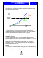
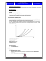
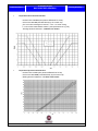
Calculating clutch degradation index
This procedure allows the MTA gearbox control unit to calculate the clutch transmissibility index
due to the contribution of the engine control unit, which can saturate the required accelerator
pedal percentage using the SW and deliver the corresponding engine torque.
The clutch degradation index calculation procedure is required by the MTA control unit because it
stores characteristic values for each specific clutch in its Eeprom, taking into account normal
clutch wear over time.
C. TRANSMITTED TORQUE
P. CLUTCH POSITION
A: NEW CLUTCH
B. DEGRADED CLUTCH
D: WORKING CURVE
Equipment required:
•
Examiner SMART/Plus
NOTES:
Procedure
1. Run statistical data deletion
2. Repeat the kiss point self-learning procedure in accordance with clutch self-calibration
enablement
3. Run the end of line/service self-calibration
31 / 47
© 2007 Fiat Group S.p.A. – All rights reserved
Fiat Group S.p.A
TEACHING GUIDE
M40 ROBOTISED GEARBOX
Training Academy
4. The degradation index is self-learnt automatically according to the procedure followed in the plant.
The dedicated procedure allows the clutch parameters to be selectively zeroed and promotes
more accurate, faster learning
Statistical data deletion
Procedure guidelines are as follows:
Cases when this must be carried out:
•
•
•
•
•
•
•
•
•
Clutch unit replacement
Kit replacement
Gearbox replacement
Lever replacement
Pump replacement
Replacement of accumulator alone
Pump relay replacement
Replacement of EVEREST key
Statistical data reset.
Reasons why it should be carried out:
Failure to run the procedure does not impair system operation.
The following counters describe the history of each component. This is the reason why the data
group associated with one of the above components must be zeroed or restored to default values
when the component is replaced. The information provided by the following counters is also used
to identify the number of manoeuvres and incorrect conditions affecting the system at the time an
error is validated.
Equipment required
•
Examiner SMART/Plus
Rewriting the control unit
The procedure follows the guidelines shown below:
Cases in which it should be carried out:
The procedure is only carried out following the replacement of the control unit.
Reasons why it should be carried out:
Failure to run the procedure does not impair system operation.
This procedure is carried out to allow the system (gearbox and kit) history to be preserved,
transferring the data from one TCU to another.
This operation may be carried out if the services required to run it are not affected, i.e. the
procedure cannot be carried out if the control unit to be replaced does not allow for the possibility
of reading the data. As stated previously, system operation is not affected in this case.
If the TCU and any other component subject to a data deletion procedure are replaced
simultaneously, the statistical data must be transcribed first and then the data relating to the
component to be replaced must be deleted afterwards.
Equipment required
•
Examiner SMART/Plus
© 2007 Fiat Group S.p.A. – All rights reserved
32 / 47
Fiat Group S.p.A.
TEACHING GUIDE
M40 ROBOTISED GEARBOX
Training Academy
Yaw sensor learning
The procedure follows the guidelines shown below:
Cases in which it should be carried out:
-
Replacing the gearbox control unit
Replacing longitudinal acceleration sensor (NYR)
Reasons why it should be carried out:
The following procedure is used to learn the longitudinal acceleration set-off value transmitted by
the NYR.
Failure to execute the procedure impairs system operation. This procedure must therefore be run
at the end of line and in service.
.
Equipment required
•
Examiner SMART/Plus
NOTES:
The yaw sensor is the same used by the ABS/ESP system, located at the vehicle centre of
gravity. Self-learning of this sensor (NYR) by the MTA control unit is necessary because the
gearbox control unit needs sensor calibration. Because the calibration signal is not added to the
network by the NFR, specific calibration by the MTA is required..
Longitudinal acceleration sensor operation
The longitudinal acceleration sensor is used to identify a gradient and find the optimum clutch
engagement management mode. In particular, with steep gradients, the MTA requires more
accurate clutch release during take-of to optimise drive torque delivery. If the UP function is
requested by using the appropriate key, the engine speed is increased during take-off to improve
vehicle take-off on gradients under difficult conditions.
This sensor also enables the MTA control unit to identify bends and inhibit gear shifts in AUTO
mode.
4. FUNCTIONAL INTERACTION WITH OTHER SYSTEMS
4.1 INTERACTION WITH ENGINE MANAGEMENT
Whilst driving, the two systems do not interact because the system does not carry out any work therefore
there is only an exchange of information and signals via the network.
When a gear change is in progress, the system must be master over the engine management, i.e. the
gearbox control system must ask the engine (via the CAN) how the engine torque should be (decreasing
whilst the clutch is opening and increasing when the gear change has been completed and the clutch is
closing).
4.2 INTERACTION WITH CRUISE CONTROL
The Cruise Control is a system that is not affected by the presence of the MTA system, but can only be
deactivated in MANUAL mode, whilst not in AUTO.
4.3 ABS INTERACTION
There is no system functional interaction logic.
33 / 47
© 2007 Fiat Group S.p.A. – All rights reserved
Fiat Group S.p.A
TEACHING GUIDE
M40 ROBOTISED GEARBOX
Training Academy
4.4 ESP-ASR-MSR INTERACTION
When the ASR is activated, the system should inhibit SPRINT departure
During the operation of the ASR or ESP, the system inhibits the AUTO UP SHIFT manoeuvre.
5. SAFETY FUNCTIONS IN THE CASE OF FAILURE
Strategies which manage incorrect commands creating potentially dangerous or critical operating conditions for
the transmission/vehicle
5.1 INCORRECT COMMANDS
•
Reverse engagement: should not be accepted with the vehicle moving (above 3.5 km/h).
•
Gear change with vehicle moving and clutch closed: the driver request should not be accepted if it
could cause engine over or under-revving.
•
Gear change with vehicle stationary and engine started: only gears enabled for take-of ( 1st, 2nd and
reverse ) are accepted
•
Switching off using the key with the vehicle moving: the system should manage the gearbox until all
the speeds monitored are zero (engine, gearbox input, gearbox output).
•
Engine starting: it should be disabled if the a gear is engaged in the gearbox and the brake pedal is
not pressed.
•
Engine starting with gear engaged: this should only be possible with the vehicle stationary, with the
accelerator pedal released, the brake pedal pressed and no faults present.
• The system should first of all place the gearbox in neutral automatically and then enable engine
starting.
• With the vehicle stationary (or almost stationary), gear change requests are only accepted if the brake
pedal is pressed.
This prevents dangerous situations in the case of commands on the lever from passengers in the
vehicle or persons outside the actual vehicle (e.g.: through the window !) or an undesired command
by the lever on the gear control lever when the vehicle is parked on a gradient.
This eliminates the risk of incorrect driver commands in critical situations (e.g.: downhill) or
inappropriate commands from passengers.
Automatic placement of the gearbox in neutral and acoustic warning for the driver (buzzer activated)
when:
•
the oil pressure is too low to manage the clutch.
•
with the engine started, if the driver opens their door to leave the vehicle (take off with the door open
is, however, allowed because the action of the driver on the brake or the accelerator is detected):
•
with engine started, gear engaged and vehicle parked if accelerator and brake commands are not
detected for at least 3 mins;
• with the engine started, gear engaged and accelerator released and brake pedal pressed for at least
10 minutes
In the presence of faults that reduce the system safety level, full operation of the vehicle is limited (e.g.:
speed limitation at 1st, 2nd, reverse, when a fault is present in the rpm or speed engagement position
sensors).
5.2
VISUAL/ACOUSTIC INFORMATION FOR THE DRIVER
The information concerns:
•
the operating state of the drive/vehicle system (gear display, fault warning light, buzzer)
•
the notification that the gear change requests made by the driver have been carried out (limited to the
situation where the vehicle is almost stationary: vehicle parking);
• acoustic signal by means of a buzzer and continuous visual signal by means of the fault warning light
(with a specific message) if a fault is detected in the system that reduces the safety level;
• the gear engaged in the gearbox is indicated to the driver on the display;
© 2007 Fiat Group S.p.A. – All rights reserved
34 / 47
Fiat Group S.p.A.
•
•
•
•
TEACHING GUIDE
M40 ROBOTISED GEARBOX
Training Academy
indication that the engine has been turned off by the driver (key off) with the gearbox in neutral (if the
vehicle could move on its own); in this case the signals are acoustic and visual (flashing “N” on
display) for 4s;
acoustic and visual signals (display) if the system intervenes to switch the gearbox automatically to
neutral;
clutch overheating signal (restricted to take-off manoeuvre); a specific notice appears on the
reprogrammable multifunction display and buzzer;
Acoustic and visual signals (display) if, after a "failed" engine starting manoeuvre, the gearbox is now
in neutral.
NOTE: The gear change request cannot always be accepted by the system (brake pedal not pressed,
Reverse request with vehicle above 3.5 km/h, etc.).
35 / 47
© 2007 Fiat Group S.p.A. – All rights reserved
Fiat Group S.p.A
TEACHING GUIDE
M40 ROBOTISED GEARBOX
Training Academy
6. MULTISTABLE LEVER
6.1 DESCRIPTION
The gear selector lever fitted on the robotized gearbox is the multistable type, i.e. with three
stable positions and three unstable positions. With reference to the diagram below, the three
stable positions are those corresponding to NEUTRAL (N = NEUTRAL) REVERSE (R =
REVERSE) and the TIP position [between the unstable UP (+) and DOWN (-) positions].
The unstable positions, positions that are abandoned by the lever as soon as it is released, are,
as stated earlier, the higher ratio request position [UP (+)], lower gear request position [DOWN (-)]
and the automatic mode request position (A/M); the return to manual mode takes place by
returning the lever to the A/M position.
6.2 KEY ON (+15)
With the vehicle stationary and the ignition in the ON position (ignition-operated electrical services
activated), the instrument panel should display the gear engaged, give an indication of the operating
mode (automatic = AUTO or manual = NO DISPLAY) and the logic (economy = E or normal - NO
DISPLAY): the letter "E" is only displayed in Automatic mode.
When the lever is operated with the brake pedal pressed only 1st, N and R can be engaged.
If the operator carries out a manoeuvre other than those described previously, the following
message appears on the control panel: “PRESS BRAKE PEDAL REPEAT MANOEUVRE”.
The repetition of the manoeuvre consists of returning the lever to the position that is consistent with the
actual gear engaged (the lever can simply be removed and returned to the position before the request)
and the request repeated with the brake pressed. the gear change request is accepted by the system.
In addition, the tip position (middle stable position between UP and DOWN) corresponds to the first
gear if the request was made with the brake pressed coming with the lever from NEUTRAL and with
the gearbox in neutral or from the lever in REVERSE and with reverse gear engaged.
© 2007 Fiat Group S.p.A. – All rights reserved
36 / 47
Fiat Group S.p.A.
TEACHING GUIDE
M40 ROBOTISED GEARBOX
Training Academy
Engine started
The vehicle starts to move (take off) using the accelerator pedal only.
Only the following gears can be engaged with the engine started: “1st”, “2nd or “R”. The gears can only be
engaged by pressing the brake pedal.
NOTE: When R is engaged there should NOT be any ACOUSTIC WARNING.
NOTE: Coming from "N" or "R" the TIP position corresponds to 1st gear. Every TIP - request is not
considered by the system because it is not a plausible request.
Any gear request with the vehicle stationary, made by the user without having pressed the brake pedal,
will be refused by the system, which will warn the driver with the message "PRESS BRAKE AND
REPEAT MANOEUVRE" in the display and an acoustic signal (the acoustic signal is deactivated the
moment consistency is restored between the lever position and the gear engaged). If a gear is requested
by means of the UP/DOWN lever position, only the message is controlled, without any acoustic signal.
Any 3rd gear request with the vehicle at a standstill, made by the user by pressing the brake pedal, will be
denied by the system, which will warn the user by showing the following message on the display
“MANOEUVRE NOT PERMITTED” (throughout the specified control time-out (8.7 seconds)) and an
acoustic signal (the acoustic signal will be deactivated when an additional gear shift request is made).
6.3 SYSTEM BEHAVIOUR WITH ENGINE STARTED AND/OR VEHICLE MOVING
Start-up (+50)
If the vehicle has been switched off previously with "N" engaged:
the vehicle can be started either with the brake pedal not pressed or with the brake pedal
pressed;
the instrument panel, in addition to displaying the operating mode and the logic already available
with the key +15, should show neutral N in the context of the starting request.
If the vehicle has been switched off previously with GEAR OTHER THAN "N" engaged:
Without the brake pedal pressed:
• the system warns the driver through the message "PRESS BRAKE" in the display and
does not allow starting; in order to start the vehicle, simply repeat the manoeuvre
pressing the brake pedal or, keeping the key in the AVV (starting) position, press the
brake pedal;
With the brake pedal pressed:
• the engine starts and the system automatically engages "N".
The instrument panel, in addition to displaying the operating mode and the logic already available
at the key on +15, displays neutral [N].
After starting, until the lever is placed in position "N", when the brake pedal is pressed, the system
will warn the driver of the inconsistency between the gear engaged in the gearbox (neutral = "N")
and the position of the lever through an acoustic signal.
37 / 47
© 2007 Fiat Group S.p.A. – All rights reserved
Fiat Group S.p.A
TEACHING GUIDE
M40 ROBOTISED GEARBOX
Training Academy
Starting the vehicle from stationary
Once the starting procedure is over, the vehicle is running, at a speed V = 0 km/h, gearbox in neutral (N)
and selector lever in N or in TIP/R.
The user can chose to set off in a forward or reverse gear.
The instrument panel, in addition to displaying the operating mode and the logic, displays neutral N.
Irrespective of the mode (Auto/Manual) or operating strategy (Eco/Normal) chosen for first or second
gear engagement, the brake pedal must be depressed and:
- place the lever in TIP if you wish to set off in 1st or, still pressing the brake pedal, request 1st by
moving the lever towards TIP+ if the user has not repositioned the lever as set out in the previous
paragraph; it should be remembered that coming from N, the TIP position corresponds to 1st gear;
- place the lever in TIP and move the lever towards TIP+ (still pressing the brake pedal) if you decide to
set off in 2nd for departures in poor grip conditions.
Gear change with vehicle moving
Two gear shift options are available depending on the system operating mode: MANUAL = No message
on display, or in AUTOMATICA = AUTO.
Engine started
The vehicle starts to move (take off) using the accelerator pedal only.
Only the following gears can be engaged with the engine started: “1st”, “2nd or “R”.
The gears can only be engaged by pressing the brake pedal.
NOTE: When R is engaged there should NOT be any ACOUSTIC WARNING.
NOTE: Coming from "N" or "R" the TIP position corresponds to 1st gear. Every TIP - request is
not considered by the system because it is not a plausible request.
Any gear request with the vehicle stationary, made by the user without having pressed the brake
pedal, will be refused by the system, which will warn the driver with the message "PRESS BRAKE
AND REPEAT MANOEUVRE" in the display and an acoustic signal (the acoustic signal is
deactivated the moment consistency is restored between the lever position and the gear
engaged).
6.4 GEAR CHANGE WITH VEHICLE MOVING
Gear change in manual mode
Every gear change request for a higher ratio takes place by moving the lever to the UP position
(+).
The requests are only accepted if the gear change is over and the engine revs are such that the
engine will not stall.
If the request is accepted by the system:
when the gear change is over, the display will show the new current gear.
NOTE: the system shows the gear actually engaged on the display and not the gear requested by
the user.
If the request is not accepted by the system:
the gear engaged before the request will remain on the display and the message "MANOEUVRE
NOT ALLOWED" will also be shown on the display accompanied by an acoustic signal.
© 2007 Fiat Group S.p.A. – All rights reserved
38 / 47
Fiat Group S.p.A.
TEACHING GUIDE
M40 ROBOTISED GEARBOX
Training Academy
In a similar way, the user can proceed and request lower ratios using the lever, placing it in the
DOWN (-) position. In this case the system will only accept the request if the engine speed, after
the gear change, does not exceed the maximum rotation speed permitted for the engine.
The system also automatically selects the lower ratio if the user keeps the current ratio at the
engine stall speed limit (AUTODOWN manoeuvre).
The lever is in the TIP position during the manoeuvres described above.
Gear change in automatic mode
The word AUTO appears on the display above the indication of the gear engaged.
To cause the vehicle to move (forward or backwards) irrespective of whether the mode is
automatic, the driver must request both possible take-off gears (1st or 2nd) or Reverse with the
brake depressed (the system will maintain automatic mode).
The system also accepts requests from the lever in this mode (both requests for higher ratios
using the TIP + and lower ratios using the TIP -) which maintain it in automatic mode
(AUTOMATIC GEAR SUGGESTION) in effect after the request made by the driver has been
accepted, the system continues to work in a completely independent way
The Kick Down function is also available: following a brisk action on the accelerator towards the
end of travel position, the system recognizes the request for maximum torque and changes down
by one, two or three gears if conditions allow.
UP/NORMAL strategy
It controls the “UP function” (heavy duty road function): a mode that allows gear shifts at
higher engine speeds in order to tackle steep roads with any kind of load.
If the system is working in automatic mode, when the UP button is pressed the letter E/UP
warning light is shown on the display. Pressing the E/UP button a second time deactivates the UP
mode (the letter E/UP warning light is no longer shown on the display (Normal logic)).
If the system is working in manual mode, pressing the UP button has no effect (nothing
shown on the display).
If the system is working in automatic mode (UP or Normal), placing the lever in A/M engages
the Manual mode and AUTO and UP are no longer shown on the display.
- If the system is in manual mode, placing the lever in A/M engages the automatic mode and the
display shows AUTO (the system also suggests the last mode (ECO or NORMAL) memorized
before the manual mode was engaged).
39 / 47
© 2007 Fiat Group S.p.A. – All rights reserved
Fiat Group S.p.A
TEACHING GUIDE
M40 ROBOTISED GEARBOX
Training Academy
6.5 REQUEST FOR NEUTRAL WITH VEHICLE MOVING
•
- If NEUTRAL is requested with the ACCELERATOR PEDAL RELEASED:
irrespective of the brake status
the system accepts the request and the display shows neutral N and also the operating mode
and logic
•
If neutral N is requested with the ACCELERATOR PEDAL RELEASED:
irrespective of the brake status
the system does not accept the request and maintains the current speed. Because the lever is in
a position inconsistent with the gear actually engaged in the gearbox, the display shows the
message “MANOEUVRE NOT PERMITTED” together with an acoustic signal.
A return from N (neutral), with the system either in AUTOMATIC or MANUAL, is achieved by
placing the lever in the stable TIP position: THE BRAKE PEDAL DOES NOT HAVE TO BE
PRESSED.
The manoeuvre restores the gearbox to the most suitable gear.
6.6 REQUEST FOR REVERSE WITH VEHICLE MOVING
Reverse gear can only be engaged in the following conditions:
brake pedal pressed
vehicle speed close to 0 km/h.
If an attempt is made to engage (R) without pressing the brake pedal and with vehicle speed up to
approx 10 km/h, the system automatically engages neutral (N) and the display shows the
message "DEPRESS BRAKE PEDAL – REPEAT MANOEUVRE"; and an acoustic signal is
emitted.
If an attempt is made to engage (R) irrespective of the action on the brake pedal and with vehicle
speed greater than 10 km/h, the system does not perform any action and the display shows the
message "MANOEUVRE NOT PERMITTED"; and an acoustic signal is emitted.
NOTE: With the brake pedal pressed, reverse gear is only engaged if the vehicle stops within
around 3 seconds.
Disengagement of reverse gear (in other words, engagement of 1st speed):
the system engages 1st gear when the lever is positioned in TIP, therefore, with the brake pedal
pressed and the vehicle speed close to 0 km/h, the system accepts the gear change.
If an attempt is made to engage 1ST gear without pressing the brake pedal and with vehicle
speed up to approx 10 km/h, the system automatically engages neutral (N) and the display shows
the message "DEPRESS BRAKE PEDAL – REPEAT MANOEUVRE"; and an acoustic signal is
emitted.
© 2007 Fiat Group S.p.A. – All rights reserved
40 / 47
Fiat Group S.p.A.
TEACHING GUIDE
M40 ROBOTISED GEARBOX
Training Academy
If an attempt is made to engage 1ST gear with the brake pedal depressed and with vehicle speed
greater than approx 10 km/h, the system does not change gear and the display shows the
message "MANOEUVRE NOT PERMITTED"; and an acoustic signal is emitted
6.7 SYSTEM SAFETY FEATURES
A)
VEHICLE STATIONARY, ENGINE RUNNING, GEAR ENGAGED (usually 1st, 2nd or R):
If the brake pedal and/or accelerator is pressed and then the driver’s door is opened, the system
maintains the current gear. The instrument panel continues to display the mode, the logic and the
current gear; no acoustic warning.
B)
VEHICLE STATIONARY, ENGINE RUNNING, GEAR ENGAGED (usually 1st, 2nd or R):
If neither the brake pedal nor the brake or accelerator pedal is pressed and the driver’s door is
opened, the system engages N after about 1.5 s.
The instrument panel will continue to display the mode, the logic and N.
Since the lever may be either in TIP or in R, the shift to N (neutral) controlled by the system
involves an inconsistent situation between the position of the lever and the gear engaged in the
gearbox, therefore the manoeuvre is accompanied by an acoustic inconsistency signal (the
buzzer is used in all cases where neutral is engaged automatically).
C)
VEHICLE STATIONARY, ENGINE RUNNING, GEAR ENGAGED (usually 1st, 2nd or R):
if no action is performed for longer than 3 minutes (i.e. neither the brake nor the accelerator pedal
is pressed and the lever is not moved (e.g. stationary at traffic lights)), the system automatically
selects N.
The instrument panel will continue to display the mode, the logic and N.
Since the lever may be in TIP or in R, the shift to N (neutral) controlled by the system involves an
inconsistent situation between the position of the lever and the gear engaged in the gearbox,
therefore the manoeuvre is accompanied by an acoustic inconsistency signal.
D) VEHICLE STATIONARY, ENGINE RUNNING, GEAR ENGAGED (usually 1st, 2nd or R):
Keeping the brake pedal pressed and not carrying out any action for more than 10 minutes, the
system automatically selects N.
The instrument panel will continue to display the mode, the logic and N.
Since the lever may be in TIP or in R, the shift to N (neutral) controlled by the system involves an
inconsistent situation between the position of the lever and the gear engaged in the gearbox,
therefore the manoeuvre is accompanied by an acoustic inconsistency signal.
E) VEHICLE STATIONARY, ENGINE RUNNING, gearbox in neutral (N), KEY-OFF
procedure:
If the engine is turned off, the instrument panel continues to display the mode, the logic and N
flashing for about 4 seconds, accompanied by an acoustic signal that the vehicle has been left
with the gearbox in neutral (N).
F) VEHICLE STATIONARY, ENGINE RUNNING, gearbox with gear OTHER THAN neutral
(N), KEY-OFF procedure:
If the engine is turned off, no information on the gearbox will be displayed.
41 / 47
© 2007 Fiat Group S.p.A. – All rights reserved
Fiat Group S.p.A
TEACHING GUIDE
M40 ROBOTISED GEARBOX
Training Academy
NOTES:
changes compared to previous systems:
No general failure warning light
Lever UP and DOWN positions reversed
Neutral accepted at any speed with accelerator released
The stable and unstable position contacts are no longer served by ordinary switches but are
Hall effect sensor magnetic contacts. This means that correct contact continuity cannot be
checked using a multimeter but only by instrumental diagnosis using an EXAMINER, analysing
the relevant parameters.
7. SPECIFICATIONS
7.1 GEAR RATIOS
Type
C546 (M40)
Transmission ratios
I
4.167
II
2.350
III
1.462
IV
1.047
0.955(*)
V
0.786
0.659(*)
VI
0.652
0.552(*)
Rev
ers
e
(*) Different conversions
© 2007 Fiat Group S.p.A. – All rights reserved
42 / 47
4.083
TEACHING GUIDE
M40 ROBOTISED GEARBOX
Fiat Group S.p.A.
Training Academy
7.2 CLUTCH
Type
Single dry plate and pressure plate with automatic
wear take-up device
Operation
Thrust
Driven plate outer
diameter (mm)
258±1
Driven plate inner
diameter (mm)
160±5
7.3 FLUIDS AND LUBRICANTS
Recommended product specifications
Hydraulic unit
fluid
Type
Selenia CS Speed
quantity
maintenance
(ATF DEXRON III)
viscosity 1800 cPs at 40 ° C;
6.5 cPs at 100 ° C
0.505 litres
Check every
30000 Km
Clutch cylinder
fluid
Check every
30000 Km
DOT4
50 cc (0.05 Litres)
Replace every 2 years
or 60000 Km
7.4 ROBOTISED GEARBOX CONTROL UNIT
Type CFC348F
80 pin connector
Temperature of working environment T:
•
From -40°C to +110° C (when active)
Operating voltage:
•
Minimum operating voltage VBAT_min:
6.0 V
•
Maximum operating voltage VBAT_max:
16.0 V
•
Typical operating voltage VBAT_typ:
12.0 V
•
Typical voltage test VBAT_test:
•
Voltage surge range
13.5 V +/- 0.2 V
26.0 V < VBAT_ovld < 40.0 V
Communication network:
•
C- CAN (500 kbytes/sec)
Special hardware functions
•
Power latch relay (internal)
•
control unit – wake up from driver’s door opening switch
43 / 47
© 2007 Fiat Group S.p.A. – All rights reserved
Fiat Group S.p.A
TEACHING GUIDE
M40 ROBOTISED GEARBOX
Training Academy
7.5 SENSOR/ACTUATOR ELECTRICAL SPECIFICATIONS
•
Linear differential transformer sensor (LVDT type- engagement and selection position)
1
2
3
4
The operation of the sensors is as follows
f the sensor is controlled by current from the control unit final stage (Faster), on the main
circuit by means of a triangular wave
f A voltage square wave is induced at the output of the secondary circuit, whose amplitude
corresponds with the effective position of the associated sensor.
Passive component characteristics:
•
•
•
•
R(2-3): 57.5 Ω ± 10% measured at 25°C
R(1-4): 26 Ω ± 10% measured at 25°C
R(1-2): > 10 kΩ
R(3-4): > 10 kΩ
© 2007 Fiat Group S.p.A. – All rights reserved
44 / 47
Fiat Group S.p.A.
TEACHING GUIDE
M40 ROBOTISED GEARBOX
Training Academy
Input-output signal graphics
•
Clutch position sensor (Hall effect)
-
Supply voltage between “+” and “–“: 5V
Output voltage between “S” and earth: 0 - 5V (directly proportional to pushrod position)
-{}-
45 / 47
© 2007 Fiat Group S.p.A. – All rights reserved
Fiat Group S.p.A
•
TEACHING GUIDE
M40 ROBOTISED GEARBOX
Training Academy
Proportional flow rate solenoid valve
- maximum flow: 10 l/min (with pressure differential of 10 bar).
- drive current: 0 to 2A (controlled directly by the control unit).
[0 to 0.9A valve discharged to reservoir; 0.9 to 1.1A valve closing;
1.1 to 2nd valve loaded toward actuator; (see specifications in Fig. XX]
- Winding electrical resistance: 2.5 Ohms ± 6% at 20°C.
•
Proportional pressure solenoid valve
- maximum flow: 7 l/min (with pressure differential of 10 bar).
- drive current: 0 to 2.5A (controlled directly by the control unit).
- Winding electrical resistance: 2.5 Ohms ± 6% at 20°C.
© 2007 Fiat Group S.p.A. – All rights reserved
46 / 47
Fiat Group S.p.A.
•
TEACHING GUIDE
M40 ROBOTISED GEARBOX
Training Academy
Pressure sensor
- Supply voltage from MTA control unit: +5 ± 0.5V (with uptake of ca10 mA).
•
Gearbox rpm sensor
-{}This electromagnetic sensor supplies the control unit with a sinusoidal signal with a frequency
proportional to the speed of a pinion fitted to the gearbox mainshaft. The winding resistance is
1200 Ohm ± 10% at 20°C. The gap is 0.2-1 mm.
7.6 GENERAL SYSTEM FEATURES
Technical specifications:
•
Operating pressure under normal conditions: between 36.5 and 46 bars. Pressure relief valve
set to approx 82 ± 10 bar.
•
Pump output >0.69 l/min at 40 bar and 12 V; current uptake < 14,4 A; control with external
relay (vehicle wiring)
•
Gear pump: Pump capacity is >0,81 l/min at 45 bar, 3450 rpm and fluid at 60 °C
•
Accumulator: volume 250 cm3, preload of 24 bar at 20 °C
47 / 47
© 2007 Fiat Group S.p.A. – All rights reserved