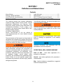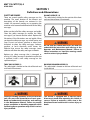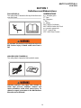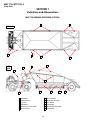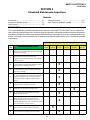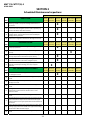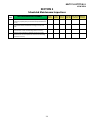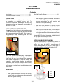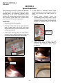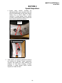
1
MHT175-CAT777-INSP-RSP-5
SPECIALTY HAULAGE SOLUTIONS FOR CONSTRUCTION AND MINING
SCHEDULED/SPECIAL
INSPECTIONS & RECOMMENDED
SUPPORT PARTS
MEGA CORP.®
700 Osuna Rd. N.E. • Albuquerque, NM 87113 • 1-800-345-8889 • 505-345-2661 • Fax 505-345-6190
www.megacorpinc.com
® MEGA Corp., Inc. All Rights Reserved
MHT175-CAT777(G)-5
4 Feb 2014
TABLE OF CONTENTS
Section 1 Definitions and Abbreviations . . . . . . . . . . . . . . . . . . . . . . . . . . . . . . . . . . . . . . . . . . . . . . . . .1-1
Section 2 Scheduled Maintenance Inspections . . . . . . . . . . . . . . . . . . . . . . . . . . . . . . . . . . . . . . . . . . .2-1
Section 3 Special Inspections . . . . . . . . . . . . . . . . . . . . . . . . . . . . . . . . . . . . . . . . . . . . . . . . . . . . . . . . . . . .3-1
Section 4 Recommended Support Parts. . . . . . . . . . . . . . . . . . . . . . . . . . . . . . . . . . . . . . . . . . . . . . . . . .4-1
A
MHT175-CAT777(G)-5
4 Feb 2014
TABLE OF CONTENTS
B (Blank)
MHT175-CAT777(G)-5
4 Feb 2014
SECTION 1
Definitions and Abbreviations
Contents
Manual Usage....................................................................1-1
Warning, Caution And Notes .......................................1-1
Use Of Shall, Will, Should And May............................1-1
Safety Messages ...............................................................1-2
Abbreviations....................................................................1-3
MHT 175 General Overview (Typical) .......................1-4
MANUAL USAGE
WARNING, CAUTION AND NOTES
This technical manual only contains information
required to safely install or service an MTT. See the
appropriate Maintenance and Operators Safety
Manual for specific vehicle system information and
maintenance procedures. If your system is not
covered in this manual please contact MEGA Corp.
Product Support Group at:
US toll free: 1-800-345-8889
Direct: 1-505-345-2661 or visit our website at
www.megacorpinc.com for more detailed contact
information.
The following definitions are found throughout the
manual and apply as follows:
Operating procedures and techniques, which could
result in personal injury and/or loss of life if not
carefully followed.
Operating procedures and techniques, which could
result in damage to equipment if not carefully
followed.
The exact location of the hazards and description of
the hazards are reviewed in this section. All personnel
working on or operating the MAC/MAT must become
familiarized with all the safety messages.
Operating procedures and techniques that are
considered essential to emphasize.
Due to the nature of these processes, ensure that all
safety information, warnings and instructions are
read and understood before any operation or any
maintenance procedures are performed. Some
procedures take place with heavy components and
at moderate heights, ensure proper safety
procedures are maintained when performing these
actions. Failure to use and maintain proper safety
equipment and procedures will cause injury, death or
damage to equipment.
USE OF SHALL, WILL, SHOULD AND MAY
Shall and Will – Used when application of a
procedure is mandatory.
Should – Used when application of a procedure is
recommended.
May - Used to indicate an acceptable or suggested
means of accomplishment.
1-1
MHT175-CAT777(G)-5
4 Feb 2014
SECTION 1
Definitions and Abbreviations
SAFETY MESSAGES
DO NOT OPERATE (2)
This safety label is located on the outside of the front
and rear control boxes (if equipped).
There are several specific safety messages on this
machine. The exact location of the hazards and
description of the hazards are reviewed in this
section. All personnel working on or operating the
machine must become familiarized with all the safety
messages.
Make sure that all of the safety messages are legible.
Clean the safety messages or replace the safety
messages if you cannot read the words. Replace the
illustrations if the illustrations are not legible. When
you clean the safety messages, use a cloth, water, and
soap. Do not use solvent, gasoline, or other harsh
chemicals to clean the safety messages. Solvents,
gasoline, or harsh chemicals could loosen the
adhesive that secures the safety messages. Loose
adhesive will allow the safety messages to detach.
Do not open this control box unless you read and
understand the instructions and warnings in the
Operator and Maintenance Manual. Failure to
follow instructions or heed the warnings could
result in serious injury or death.
Replace any safety message that is damaged or
missing. If a safety message is attached to a part that
is replaced, install a new safety message on the
replacement part.
TOXIC GAS HAZARD (1)
This safety label is located on the side of the tank and
at all water fill entrances.
BACKING RUNOVER HAZARD (3)
This safety label is located on the rear of the tank and
inside the cab.
Cutting or welding operation on the inside of the
tank can cause the accumulation of toxic gases.
Read and understand instructions and warnings
in the Maintenance Manual. Failure to provide
proper ventilation or breathing apparatus while
conducting these operations may result in serious
injury or death.
The vehicle is equipped with a back-up alarm.
Alarm must sound when operating this vehicle in
reverse. Failure to maintain a clear view in the
direction of travel could result in serious injury or
death.
1-2
MHT175-CAT777(G)-5
4 Feb 2014
SECTION 1
Definitions and Abbreviations
ABBREVIATIONS
FALL HAZARD (4)
This safety label is located at the top of the front and
rear of the tank.
e.g. - example given
FT - Feet
Kg - kilograms
l - liters
m - meters
MHT - MEGA Coal Hauler
MHT - MEGA Hauler with Truck
psi - pounds square inch
SQ FT - Square Feet
VDC - Volts Direct Current
Do not walk on the top of tank without fall arrest
PPE. Serious injury or death could occur from a
fall.
HIGH PRESSURE CYLINDER (5)
This safety label is located on the hydraulic motor.
Hydraulic cylinders and supply lines contain oil
under high pressure. Improper removal and
repair procedures could cause severe injury. To
remove or repair, instructions in the Maintenance
Manual must be followed.
1-3
MHT175-CAT777(G)-5
4 Feb 2014
SECTION 1
Definitions and Abbreviations
MHT 175 GENERAL OVERVIEW (TYPICAL)
4
3
TOP VIEW
7
2
SIDE
VIEW
1
3
4
10
9
8
11
1
2
3
4
5
6
2
12
6
GOOSENECK
LOWER HOPPER
SIDE WALL
REAR BOGIE
REAR AXLE & WHEEL GROUP
HITCH & SADDLE
7
8
9
10
11
12
1-4
12
DECK & FENDER
TURN LIMIT INDICATOR
SPILL GUARD
SIDE BOARDS
END-OF-LOAD INDICATOR
JACKING PADS
5
MHT175-CAT777(G)-5
4 Feb 2014
SECTION 2
Scheduled Maintenance Inspections
Contents
Description .........................................................................2-1
Suspension & Brake System .........................................2-1
Door System.......................................................................2-2
Electrical System ..............................................................2-2
MHT Structure & Hitch Assembly...............................2-2
DESCRIPTION
This section establishes scheduled maintenance inspections of the MHT175 trailer (MHT) and associated systems at the designated frequencies. Performing these inspections will identify potential system discrepancies
and allow preventative maintenance to be performed before a component or system is rendered totally inoperative. Once again, these inspections are in addition to and do not replace existing CAT scheduled inspection
requirements.
FREQUENCY
STEP
SUSPENSION & BRAKE SYSTEM
WEEKLY (150 HRS)
BI‐WEEKLY (250 HRS)
MONTHLY (500 HRS)
1
Check trailer axle and wheel group components as defined in CAT 777F Service Manual. Service individual components as required. 2
After initial installation or and system component replacement, follow chassis required initial maintenance schedule for that component or system. Service as required.
3
Check trailer axle struts, a‐frame and pan‐hard rod for security, damage and evidence of lubrication. Inspect lubrication lines for damage and security.
X
4
Check rear axle housing and access plate for damage security and leaks. Inspect axle sump breathers for evidence of oil leakage. X
5
Inspect axle final drives for proper fluid level. If more than 3 Quarts (2.84 liters) are added at any inspection, remove axle inspection cover to check spindle vent cover plates security and signs of leakage. Repair as required.
X
6
MHT rear bogie brake cooling filter assemblies and manifolds for leaks, damage and security. X
7
Replace MHT rear axle brake cooling oil filters.
8
MHT rear bogie brake accumulators and relay for damage, security and leaks.
X
9
All brake system cooling and activation hoses for damage, security and leaks. Ensure the tractor integration points are also inspected (e.g. junction manifolds, scavenge pump, tank, E‐brake, proportional group, accumulators, oil cooler union…).
X
10
MHT bolster (side wall tunnels containing hydraulic hoses) cavity drain holes for evidence of leaking.
11
Tractor brake relay for damage, security and leaks.
QUARTERLY (1000 HRS)
SEMI‐ANNUAL (2500 HRS)
X
X
X
2-1
ANNUALLY (5000 HRS)
MHT175-CAT777(G)-5
4 Feb 2014
SECTION 2
Scheduled Maintenance Inspections
FREQUENCY
STEP
1
2
3
4
STEP
WEEKLY BI‐WEEKLY MONTHLY QUARTERLY SEMI‐ANNUAL ANNUALLY (150 HRS) (250 HRS) (500 HRS) (1000 HRS)
(2500 HRS)
(5000 HRS)
DOOR SYSTEM
Check all door cylinders for damage, security and leaks. Attaching hardware and pins for damage and evidence of lubrication.
Check all door activation hoses for damage, security and leaks. Ensure the tractor integration points are also inspected (e.g. junction manifolds, hoist valve and tank). Check gooseneck components (flow divider, pressure regulator valves, counter balance valve and manifolds) for damage security and leaks.
WEEKLY BI‐WEEKLY MONTHLY QUARTERLY SEMI‐ANNUAL ANNUALLY (150 HRS) (250 HRS) (500 HRS) (1000 HRS)
(2500 HRS)
(5000 HRS)
ELECTRICAL SYSTEM
2
Check door indicator switch and cabling for damage and security. 3
Check MHT rear bogie electrical junction box for damage and security. Inspect all wire terminals strips for security.
4
Check gooseneck electrical cabling for damage and security from the boom collar to the tractor integration point.
5
Check electric turn stop indicator, lights, backup alarms, cab light/alarm assembly for damage, security and proper operation.
X
X
WEEKLY BI‐WEEKLY MONTHLY QUARTERLY SEMI‐ANNUAL ANNUALLY (150 HRS) (250 HRS) (500 HRS) (1000 HRS)
(2500 HRS)
(5000 HRS)
MHT STRUCTURE & HITCH ASSEMBLY
Check MHT rear axle mounting structure and upper rear deck for damage and cracks.
2
Check MHT rear bumper assembly for damage, security and cracks.
3
Check lower hopper assembly and dump doors for security, damage and cracks.
4
Check all MHT interior and exterior walls for damage and cracks.
5
Check gooseneck assembly for damage and cracks. Inspect gooseneck turn limit cheeks for evidence of turn limit indicator contact. 6
Check ball hitch skirt assembly for damage, security and cracks.
9
X
X
X
1
8
X
X
Check all MHT tail and clearance lights for damage, security and proper operation.
7
X
Check tractor integration manifolds for damage and security.
1
STEP
X
Remove ball skirt and inspect upper retention plate for broken bolts and evidence of spherical ball contact with the upper retention plate. Ensure upper spherical ball shows evidence of lubrication.
Check clearance between hitch spherical ball and upper brass bushing. If gap is more than 0.010” shim upper brass bushing as described in MHT175‐CAT777(G)‐4.
Check tractor fender assemblies for damage, security and cracks 2-2
X
MHT175-CAT777(G)-5
4 Feb 2014
SECTION 2
Scheduled Maintenance Inspections
STEP
WEEKLY BI‐WEEKLY MONTHLY QUARTERLY SEMI‐ANNUAL ANNUALLY (150 HRS) (250 HRS) (500 HRS) (1000 HRS)
(2500 HRS)
(5000 HRS)
MHT STRUCTURE & HITCH ASSEMBLY
Check hitch receiver and saddle assembly mounts for damage and security. Inspect pivot pins and hitch clamp assemblies for security.
Check tractor fender assemblies for damage, security and cracks Check deck assembly for damage, security and cracks. Inspect deck mounts for cracks and mounting bolts for security.
Check turn stop indicator for damage, security and cracks. Inspect chassis rail mount plates for cracks and all mounting hardware for security.
2-3
MHT175-CAT777(G)-5
4 Feb 2014
SECTION 2
Scheduled Maintenance Inspections
2-4 (Blank)
MHT175-CAT777(G)-5
4 Feb 2014
SECTION 3
Special Inspections
Contents
Description .........................................................................3-1
Turn Limit Indicator Contact ........................................3-1
Hitch Ball Over Oscillation ............................................3-1
DESCRIPTION
3. Check adjoining gooseneck interior and exterior
structure for damage. Inspect gooseneck
structure and plating for weld cracking and
evidence of steel plate buckling.
This section contains special inspection requirements
for exceeding an establish system limit. The
established inspections are designed to reveal any
damage sustained and determine serviceability of
the MHT175 system.
4. Check turn limit indicator for damage. Inspect
plates and welds for cracks and deformities.
TURN LIMIT INDICATOR CONTACT
5. Check turn limit indicator deck and horse collar
mounts for damage. Inspect rail mounting plates
and angle brackets for cracks and loose hardware.
The metal turn limit indicator is designed to provide
a visual indication to the operator they have reached
the maximum rotation of the MHT. This is noted by
the gooseneck cheek contacting the turn limit
indicator as shown below.
Contact MEGA Product Support at: 1-800- 345-8889
for any major structural repair issues.
Gooseneck
Cheek
HITCH BALL OVER OSCILLATION
The hitch ball assembly is designed to oscillate 12
degrees within the lower socket assembly as shown
below. This allows the MHT175 a large range of
motion when operating in the pit, on haul road, on
coal piles and when unloading the trailer (MHT).
Retention
Plates
Metal Turn Limit
Indicator
Ball Hitch
When the system experiences high impact loads
damage may occur to both the gooseneck cheek
plates and the turn limit indicator. The gooseneck
cheek plates may buckle or begin to weaken and
eventually cause further damage to adjoining
gooseneck plate structure. The turn limit indicator
may experience excessive bending moments and
begin to tear or weaken lower mount plate and horse
collar welds.
12
Retention
Plates
INSPECTION
1. Remove a gooseneck access cover.
Ball to
Retention
Plate
Contact
2. Check gooseneck cheek structure for damage.
Inspect welds for evidence of cracking and metal
plates for signs of buckling.
3-1
MHT175-CAT777(G)-5
4 Feb 2014
SECTION 3
Special Inspections
4. If hard contact is confirmed, remove upper
retention plates and inspect the upper retention
plates, brass bushings and lower receiver as
follows:
a. Inspect upper retention plates for
mushrooming of flat mating ends. Lay the
retention plate on a flat surface and check for
warpage. If retention plate is mushroomed or
warped the retention plate set must be
replaced.
When operating the MHT175 beyond the allowable
12 degree limit, the ball will contact the upper
retention plate and potentially damage several
components of the system. Repeated and hard
contacts will damage upper retaining plates, upper
brass bushings, mount bolts and in severe cases
cause structural damage to the gooseneck.
INSPECTION
1. Remove hitch ball skirt assembly.
2. Check for broken bolts on the upper retaining
plate. If mount bolts are missing, have been
sheared off or laying on the lower receiver, severe
contact has occurred.
Mushrooming
Joint
3. Check upper retaining plates and hitch ball for
damage. Inspect retaining plates and hitch ball
for evidence of hard contacts as shown below.
b. Check upper brass bushings for over
oscillation ball contact as shown below. If
contacted and deformed replace upper
bushing set.
Ball Contact
Retention
Plate Contact
3-2
MHT175-CAT777(G)-5
4 Feb 2014
SECTION 3
Special Inspections
c. Inspect lower receiver assembly for
elongated/pulled upper retention plate bolt
holes and deformation of the lower receiver
mount ring as shown below. If either
condition is noted replace lower receiver
assembly. Contact MEGA Product Support for
lower receiver replacement options.
Deformed
Mount Ring
Elongated/Pulled Threads
5. Check interior and exterior gooseneck structure
and plating for damage. Inspect gooseneck
structure and plating for weld cracking and
evidence of steel plate buckling. If either
condition is noted contact MEGA Product
Support at: 1-800-345-8889.
3-3
MHT175-CAT777(G)-5
4 Feb 2014
SECTION 3
Special Inspections
3-4 (Blank)
MHT175-CAT777(G)-5
4 Feb 2014
SECTION 4
Recommended Support Parts
Contents
Description .........................................................................4-1
Door System Parts Group..............................................4-1
Brake System Parts Group.............................................4-1
Hitch Assembly Parts Group ........................................4-1
Miscellaneous Parts Group...........................................4-2
DESCRIPTION
This section contains a listing of recommended support parts that should be available in the supply
warehouse. The tables are categorized by specific sub system of the MHT. DO NOT FORGET that all MHTs are
not configured the same and there are several variations of hydraulic systems, door cylinder configurations and
turn limit indicators. Ensure MHT serial numbers and actual component part numbers are checked before
ordering any parts. Once parts are issued from warehouse stock ensure depleted quantities are replenished to
keep the recommended support parts package at 100%.
A. DOOR SYSTEM PARTS GROUP
PART DESCRIPTION
1.
2.
3.
4.
Cylinder, Hyd. *MHT Serial No. Specific Part (4 Cylinder Config)
Valve, Counterbalance (Door Close Circuit)
Switch, Limit
Bushing, Rexnord (Door Pivot)
PART NO.
QTY
302829
305323
305927
354368
1
1
1
12
PART NO.
QTY
303191
303189
303192
2
1
1
PART NO.
QTY
038904
350433
350009
350400
350008
1
4
4
4
4
B. BRAKE SYSTEM PARTS GROUP
PART DESCRIPTION
1. Filter, (7G-5000)
2. Temp Sensor (7N-7854)
3. O-Ring, 115 (Temperature Sensor)
C. HITCH ASSEMBLY PARTS GROUP
PART DESCRIPTION
1.
2.
3.
4.
5.
Shim Set 18” Ball (Ball Hitch)
Screw, Cap 1” x 5.5”
Washer, Flat 1”
Screw, Cap 7/8” x 5.5”
Washer, Flat 7/8”
4-1
MHT175-CAT777(G)-5
4 Feb 2014
SECTION 4
Recommended Support Parts
D. MISCELLANEOUS PARTS GROUP
PART DESCRIPTION
1.
2.
3.
4.
5.
6.
7.
Seal, O-ring -20
Seal, O-ring -24
Seal, O-ring -32
Seal, O-ring -40
Light, Work, 24 VDC
Light, LED, Clearance, Red
Light, LED, Clearance, Amber
PART NO.
QTY
354815
354816
354817
354818
300777
355374
355375
8
6
6
2
1
1
1
If your system is not covered in this manual or are having difficulties locating the necessary components please
contact MEGA Corp. Product Support Group at:
US Toll Free: 1-800-345-8889 or
Direct: 1-505-345-2661 or visit our website at www.megacorpinc.com for more detailed contact information.
4-2