1
DISHWASHER
RANGE
and COMPACTOR
STUDYCOURSE
UNDERSTANDING RANGE:
• GAS COMPONENTS and
FLAME ADJUSTMENTS
Module 2
LIT 4314425 Rev. C
WHIRLPOOL CORPORATION does not assume any responsibility
or any liability in connection with the use of this manual.
© 1991, 1993, 1994, 2000 WHIRLPOOL CORPORATION
All rights reserved. No portion of this book may be reproduced in any form without
written permission from WHIRLPOOL CORPORATION.
® The trademarks WHIRLPOOL ,
trademarks of Whirlpool Corporation.
,
, and FSP are registered
INTRODUCTION
The material presented in this module is intended to provide you with an understanding of the
fundamentals of range servicing.
Major appliances have become more sophisticated, taking them out of the screwdriver and pliers category.
Their electrical circuits include several different types of automatic controls, switches, heaters, valves, etc..
Semiconductors, solid-state controls, and other components usually associated with radio and television
electronic circuits, are being engineered into automatic washers, dryers, dishwashers and refrigerators.
The appliance technician is emerging into a professional status of his own. He must prepare himself now
to be able to perform his duties today as well as to retain his professionalism in the future.
No longer is on-the-job training sufficient to prepare technicians for the complicated procedures required
for todays sophisticated appliances. This training can best be obtained through organized classroom study
and application. However, much of the knowledge necessary to service todays appliances can be obtained
through study courses. Completion of this and other courses will provide you with sufficient understanding of
appliances and their operation to enable you to do minor service. It will also serve as a valuable stepping
stone to more advanced study and on-the-job training to improve your servicing skills.
Information contained in this module is used on WHIRLPOOL® appliances.
1
TABLE of CONTENTS
PAGE
CHAPTER 1 - GAS DESCRIPTIONS and BASICS........................................................... 3
Gas Description ................................................................................................................ 3
Gas Basics .......................................................................................................................... 3
Heat Energy .................................................................................................................... 3
Fuel Types ....................................................................................................................... 3
Characteristics of Gas Fuels ....................................................................................... 3
Boiling Point of Gas ...................................................................................................... 4
Combustion Triangle .................................................................................................... 4
Ignition Temperature ................................................................................................... 4
Flammability Range ..................................................................................................... 4
Flame Characteristics .................................................................................................. 4
CHAPTER 2 - BASIC PRINCIPLES of GAS COMPONENTS ........................................ 5
Burners ............................................................................................................................ 5
Gas Valves ....................................................................................................................... 6
Top Burner Valves ........................................................................................................ 6
Orifice Selection ............................................................................................................ 6
Pressure Regulators ..................................................................................................... 6
Gas Distribution ............................................................................................................ 7
Gas Pressure Testing .................................................................................................... 7
Thermostat (Gas Ovens) .............................................................................................. 8
CHAPTER 3 - STANDING PILOT IGNITION SYSTEMS ............................................... 9
Burner Assembly ........................................................................................................... 9
Oven System .................................................................................................................. 10
Lighting the Range ...................................................................................................... 10
CHAPTER 4 - SPARK IGNITION SYSTEMS ................................................................... 11
Ignitors ........................................................................................................................... 11
Spark Module ................................................................................................................ 11
Top Burner Ignitors ..................................................................................................... 12
Oven Ignitors ................................................................................................................. 12
Re-Ignition ..................................................................................................................... 12
CHAPTER 5 - GLO IGNITION SYSTEMS ......................................................................... 13
Top Burner Ignition ..................................................................................................... 13
Oven Burner Ignition .................................................................................................. 13
Safety Valve ................................................................................................................... 14
Broiler Burner .............................................................................................................. 14
CHAPTER 6 - GAS CONVERSION ..................................................................................... 15
Natural to LP Gas Conversion .................................................................................. 15
Pressure Regulator Change ....................................................................................... 15
Burner Orifice Hood Adjustment ................................................................................ 16
Top Burners ................................................................................................................... 16
Oven Burner .................................................................................................................. 16
Select-A-Gas Screw ...................................................................................................... 16
Broil Burner Orifice Spud .......................................................................................... 16
TEST ............................................................................................ See Test Book LIT4314428
*NOTE:
2
We recommend taking the TEST for MODULE 2, right after studying it.
CHAPTER 1
GAS DESCRIPTIONS and BASICS
GAS DESCRIPTION
A simplified description of a gas range would be: an
insulated metal cabinet containing four gas burners
on its top and gas-heated oven cavity inside. Gas is
piped to each of the burners where it is mixed with air
and allowed to escape from a series of small holes. It
is ignited as it flows out the burner holes. The rate of
its flow is regulated so that it burns completely and
cleanly with flames that can vary from match-head
size up to 3/4 inches in length, depending on the
application. Some adjustments necessary for proper
operation are: gas input, gas pressures, air mixtures,
pilot regulation and temperature control adjustments.
GAS BASICS
HEAT ENERGY
The heat energy produced when burning a gas fuel is
commonly expressed in British Thermal Units, or
B.T.U.'s.
1 B.T.U. = the amount of heat needed to raise one
pound of water 1 degree F.
(A wooden kitchen match produces about 1 B.T.U. of
heat.)
Gas suppliers remove the heavier hydrocarbons and
leave only methane and ethane. In some areas, natural
gas contains hydrogen sulfide and is called “sour” gas.
Sour gas corrodes copper and brass parts and
aluminum orifices must be used in these supply
areas.
Natural gas is lighter than air. It has a heat value
between 900 and 1200 B.T.U. per cubic foot.
No. 2 MIXED GAS: Made from a mixture of natural
and manufactured gas. Lighter than air, it has a heat
value between 700 and 900 B.T.U. per cubic foot.
No. 3 MANUFACTURED GAS: Made from coal and
petroleum and has a heat value of 500 to 700 B.T.U.
per cubic foot. It is also lighter than air.
No. 4 LIQUEFIED PETROLEUM GAS (LP): Mainly
propane with a heat value of 2500 B.T.U. per cubic
foot or butane with a heat value of 3200 B.T.U. per
cubic foot. LP gas is converted to liquid under moderate
pressure and is easily transported in pressurized
tanks. When released to normal atmospheric pressure
and temperature the liquid returns to its gaseous
form. LP gas is heavier than air and will lay in the
lowest spot it can find if it is released into a room.
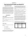
CHARACTERISTICS of GAS FUELS
GAS FUELS
FUEL TYPES
There are four types of gas fuels and are referred to by
a number.
No. 1 = natural gas
No. 2 = mixed gas
BTU VALUE/CU. FT. SPECIFIC GRAVITY
NATURAL
1075 (MAY VARY FROM
900 TO 1200)
.65 TO .70
MIXED
800 (MAY VARY FROM
700 TO 900)
.50
MANUFACTURED
535 (MAY VARY FROM
500 TO 700)
.38 TO .40
PROPANE
2500
1.53
BUTANE
3200
2.0
No. 3 = manufactured gas
No. 4 = liquefied petroleum gas (LP)
No. 1 NATURAL GAS: Found underground and is
called “wet gas” since it contains heavy hydrocarbons
such as propane, butane, and other substances.
3
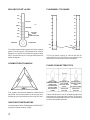
BOILING POINT of GAS
FLAMMABILITY RANGE
200°
100
100
90
90
80
80
70
70
60
60
50
50
40
40
30
30
20
20
100°
32°
BUTANE
LP
ZERO
-44°
PROPANE
-100°
NATURAL
MIXED
MANUFACTURED
-200°
-300°
DEGREES
FAHRENHEIT
14%
10
4%
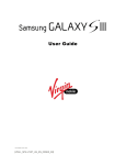
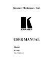
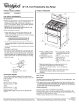
This chart shows the boiling point of the four types of
gases. The boiling point is the temperature at which
gas will turn from its liquid state to its gaseous state.
NOTE: Butane will not turn into gas at temperatures
below 32 degrees.
FUEL
0
10%
10
2%
0
This is the proper mixture, or ratio of gas and air
required for burning. Too little or too much gas in the
mixture will not allow burning to take place.
COMBUSTION TRIANGLE
FLAME CHARACTERISTICS
EN
FU
YG
EL
OX
HEAT
Fuel, oxygen, and heat are needed for combustion to
take place. All must be present for burning to start.
Remove any of the three and the burning will stop.
IGNITION TEMPERATURE
It takes between 900 to 1200 degrees FAHRENHEIT
to ignite the gases used by ranges.
4
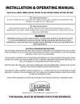
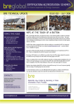
IDEAL FLAME
EXCESSIVE GAS
SHARP,BLUE/WHITE
SOFT FLAME
INNER CONE
YELLOW COLOR
ROUNDED,BLUE
SOOTY
OUTER FLAME
ADJUST AIR
NO YELLOW IN
SHUTTER
FLAME
EXCESSIVE AIR
NARROW FLAME
NOISY
AIR GAP (LIFTING)
ADJUST AIR
SHUTTER
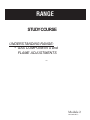
Flame characteristics can be changed by adjusting
the primary air intake at the air shutter. On burners
that do not have adjustable shutters, kits are available
to make adjustments possible.
CHAPTER 2
BASIC PRINCIPLES of GAS
COMPONENETS
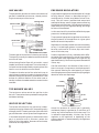
BURNERS
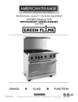
Gas ranges make use of the fact that gas fuel, if
burned in the proper mixture with air, provides a hot
flame that is odorless and entirely free of dangerous
gases. Air mixed with the gas as it enters the burner
assembly, is called “primary air.” This air may be
adjusted by the air shutter to give the flame the
proper characteristics. Gas is injected into the burner
through an orifice, which raises the velocity of the
gas. The high velocity for the stream of gas causes a
drop in pressure around the stream. Air from outside
the burner flows into this region of low pressure
through the air shutters or mixing shield.
PRIMARY
AIR
ORIFICE
AIR
SHUTTER
GAS-AIR
MIXTURE
VENTURI
BURNER HEAD
Too little primary air will produce a soft yellow flame.
The air that is surrounding the burner head is called
“secondary air.” The design of the burner head and
the aeration pans provides for an adequate supply of
secondary air, which makes it unnecessary for the
technician to be further concerned with it.
The air and gas together pass through a narrow
passageway (known as a throat) into the venturi or
mixing chamber. The sides of the venturi slope outward increasing the volume of the gas and air. As the
gas and air expand into the increased volume, their
velocity is reduced and they become thoroughly mixed.
OPEN
CLOSED
The burner throat and venturi must be in line with
the gas stream leaving the orifice. If they are not in
line, the velocity of the gas flow to the burner will be
reduced. The gas stream will hit the sides of the
venturi, bounce from side to side, slowing the flow.
Without the proper gas velocity, the aspiration or
suction effect needed to pull in air through the air
shutter will not be sufficient. The burner will have a
yellow flame that shutter adjustments may not affect
or eliminate.
MISALIGNED
VENTURI
Incorrectly aligned venturi and orifice can be due to
valve installation, poorly drilled orifice or burner
installation. Dirt or cobwebs in the venturi can cause
the same effect.
From the venturi, the mixture passes into the base of
the burner, which is a hollow chamber from which the
gas-air mixture flows to the burner ports. These ports
are designed with sufficient depth and cross-section
to further reduce the velocity of the mixture and
provide a stream of gas of the proper size to combine
with the secondary air and provide complete combustion. The head of the burner is shaped to provide
unrestricted flow of secondary air to the flames.
5
GAS VALVES
PRESSURE REGULATORS
The purpose of a gas valve is to control the amount of
gas that is admitted to the burner, thereby controlling the heat output of the burner.
A gas pressure regulator should be used on all ranges
burning Natural, Mixed, or Manufactured gas. It
would be set for 4 inches, wcp (Water Column Pressure). This will insure a constant heat output and
stable pilot flames, even if the gas pressure entering
the house should fluctuate. If the gas supply pressure
drops below the 4-inch regulator setting, the range
burners will be affected.
ORIFICE HOOD
VALVE CLOSED
VALVE PLUG
PASSAGEWAY
(CLOSED)
VALVE OPEN
PASSAGEWAY IN PLUG
ALIGNED WITH
PASSAGEWAY IN HOUSING
The basic gas valve consists of a housing and a plug.
The housing is usually threaded on one end to receive
an orifice or hood.
Valves having fixed orifices will not contain a spud
(needle) and cannot be adjusted. The valve shown is
universal and can be adjusted by screwing the orifice
hood in or out to attain the correct flame.
Threads on the other end of the valve hold a cap to
retain the spring and plug in place. A stem on the plug
extends through the cap and is provided with a flat
surface for positive location of the valve knob or
handle. A bottom-threaded extension screws into the
manifold.
In this case, the utility should be notified that proper
pressure is not being maintained.
The purpose of a gas pressure regulator is to maintain
the gas pressure to the appliance at a given point
below the house inlet pressure.
Regulators are already located at the tank assembly
on any LP or bottle gas systems. Its pressure should
be set at a minimum of 11 inches, wcp. and a maximum of 14 inches, wcp.
Pressure regulators will vary somewhat with different design and manufacturing, but all have a basic
function. Most small regulators of this type will not
operate efficiently if the inlet line pressure exceeds 18
inches, wcp.
Gas flow should be in the direction of the arrow. If
there is a surge in line pressure, the diaphragm will
flex upward, reducing the valve opening to a point
where the gas pressure counteracts the spring weight
above the valve and diaphragm.
SCREW
SPRING
DIAPHRAGM
TOP BURNER VALVES
The top burner valves control the gas flow to the
burners. These valves have a predetermined gas flow
and detent settings.
VALVE
INLET
OUTLET
ORIFICE SELECTION
The correct orifice size for any gas burner is determined by the rating of the burner, the specific gravity
of the gas, the BTU heating value per cubic foot of the
gas, and the water-column pressure of the gas source.
In the event the specific gravity or heat content of the
gas in a particular area is unknown, contact the
utility for this information. Be aware of local codes,
ordinances and regulations.
6
House line pressure for natural gas is generally
considered properly regulated at a minimum of 6
inches, wcp. and a maximum of 14 inches, wcp. This
is reduced to approximately 4 inches, wcp. by the
regulator on the appliance, or depending on the
pressure desired or recommended by the appliance
manufacturer.
GAS DISTRIBUTION
GAS PRESSURE TESTING
Gas in the street mains may be under one of three
pressure systems: low, medium, or high.
How do we test gas flow pressure in an appliance?
Low-pressure systems were used in the early days of
the gas industry, when gas was used mainly for
lighting. These mains carried pressures up to 10
inches, wcp.
As loads on low-pressure mains reached the capacity
of the mains, and were still increasing, the only way
of increasing the capacity was to increase the pressure.
To test gas pressures, you can use a water-tube
manometer which reads in inches wcp. It is sometimes called a “U” gauge. This essential tool is a
simple, clear plastic tube with a scale marked off in
inches and tenths. If used correctly, the operation is
simple and the reading accurate. However, misuse
can vary the reading enough to render it useless.
6
5
Medium-pressure distribution systems carry from 10
inches, wcp. to 50 psi {Pounds Per Square Inch} in the
street mains. Many utilities maintain an average of
15 lbs. pressure in their medium-pressure lines.
High-pressure mains carry 50 psi to 100 psi. It is
obvious that high pressure must be reduced; therefore there is a need for pressure regulators. On high
or medium-pressure mains the gas utility has a
regulator, usually near the meter, which reduces the
main pressure from psi to 6 inches wcp as it enters the
house.
We have mentioned gas pressures in inches water
column pressure and also in pounds per square inch.
For the purposes of conversion, 27.74 inches wcp
equals 1 psi. You can see that when we say the gas
pressure at the range should be 4 inches wcp, this is
less than .144 or a fraction over 1/8 psi in pressure.
You can hardly hear it. When you are checking pipe
joints with soap suds for possible leaks, you must
work carefully and thoroughly.
OUTLET
VENT
4
3
2
READ
TOTAL
DIFFERENCE
TO ORIFICE
1
0
1
2
WATER
COLUMN
3
4
5
6
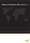
To use this manometer correctly, the following procedures are recommended:
1. Fill the tube with clear water to about the ZERO
marking on the scale. Volume of water is not critical
since the reading is the difference between the two
sides.
2. Connect the hose to one of the top gas valve
orifices. The other end is connected to the manometer.
3. Light one of the other burners - turn to full flame.
This will allow you to read “flow” pressure. Failure to
do this will only give you “static” pressure.
4. Turn on the valve leading to the manometer.
5. Hold the “U” gauge vertically and take reading.
Read each side to the tenth.
DIAPHRAGM
MERCURY CUP
VALVE
INLET
This is a cut-away view of a regulator which will
reduce pressures from psi to inches wcp. It is larger
than the regulator we use on an appliance and has a
somewhat different action, although the principle is
the same.
6. The top of the water column in each side of the
tube is not flat, but curved upward at the edges. This
is called a meniscus. Always read the lower edge of
the meniscus, keeping the eyes level with the bottom
of the curve for accurate readings. Add the readings
of the two sides for the gas pressure.
What reading do you get on this manometer?
You should read it as 4.5 inches wcp. Add the 2.4
inches above the “0” to the 2.1 inches below the “0” to
find a total of 4.5 inches wcp.
7
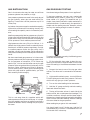
THERMOSTAT (Gas Ovens)
The purpose of gas thermostats is to maintain as
nearly even temperatures as possible in the oven so
that the cooking can be accurately controlled.
Gas thermostats are basically the same for almost all
models. When a thermostat is turned on, it allows gas
from the manifold to flow to the safety pilot and then
to the burner. When the thermostats sensing element
in the oven cavity is heated by the ovens temperature,
it signals the thermostat to restrict or shut off the gas.
The thermostats response to this signal is controlled
by the degree of heat selected on the thermostat dial.
This signal is accomplished by temperature-sensitive
fluid in the sensing element connected by a capillary
tube to the thermostat. When the signal becomes
stronger than the dial setting, the thermostat reacts
to limit the gas flow. The fluid expands against a
“bellows” in the thermostat which then mechanically
restricts the gas supply. If the thermostat capillary is
broken or has lost its fluid, the thermostat will act as
if it was cold and will not shut the gas off.
HEAT SENSING
CAPILLARY TUBE
BYPASS
ADJUSTMENT
OVEN
THERMOSTAT
HEATER PILOT
ADJUSTMENT
OVEN
BURNER
HEATER PILOT
LINE from
THERMOSTAT
GAS SUPPLY
from MANIFOLD
PILOT
VENTURI
AIR
SHUTTER
CONSTANT BURNING
PILOT SUPPLY from
FILTER on MANIFOLD
TEMPERATURE ELEMENT
GAS SUPPLY LINE
for OVEN BURNER
ORIFICE
SAFETY PILOT
VALVE
The safety pilot is considered part of the oven control
and must be studied to understand how the thermostat works. The constant-burning pilot, at the burner,
is supplied gas from the manifold, not from the
thermostat. This pilot does not ignite the main burner.
When the thermostat is turned on, it immediately
8
supplies gas to another, larger heater pilot. This large
heater pilot is ignited by the constant pilot. The
thermostat may cycle the burner flame but this large
pilot is on whenever the thermostat is on. When the
thermostat is turned off, the lack of the large pilot
flame causes the safety pilot to shut off the gas
supply. Thus, the gas is turned off at two points; at the
thermostat and at the safety pilot
Some ranges are equipped with a Lo-Temperature
thermostat. This new system gives precise control of
gas oven temperatures down to 140°F, instead of the
minimum of 200°F, which usually is the lower limit of
standard controls.
At temperatures above 325°F, the oven thermostat
operates in the same way as the standard oven
control. Below 325°F, the operation is somewhat
different. At these lower temperatures, the bypass
flame tends to override the temperature setting so
the oven burner shuts off completely. When the temperature drops to a point where more heat is called
for, the oven burner automatically relights. It then
stays on until the oven reaches the desired temperature, then shuts off again. To accomplish this on-off
cycling, which is necessary for low-temperature control, the thermostat shuts off the gas to the large
heater pilot. This, in turn, shuts off the gas flow to the
oven burner. When oven temperature drops below
the set point, gas again flows to the burner pilot,
which is promptly relighted by the stand-by pilot. The
flame of the burner pilot actuates the temperatureresponsive element, opening the automatic pilot valve
and allowing gas to flow again to the burner.
In this way, low oven temperatures are controlled as
accurately as high temperatures, there are no wide
temperature swings.
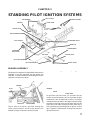
CHAPTER 3
STANDING PILOT IGNITION SYSTEMS
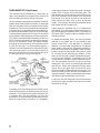
PILOT COVER
TOP BURNERS
CONTROL KNOBS
FLASH TUBE
VENTURI
AIR
SHUTTER
ORIFICE HOOD
OVEN THERMOSTAT
PILOT TUBING
TOP BURNER VALVE
MANIFOLD
OVEN BURNER
PRESSURE
REGULATOR
ORIFICE HOOD
SHUTTER
PILOT ADJUSTMENT
SAFETY VALVE
PILOT/HEATER PILOT
BURNER ASSEMBLY
Gas enters the range and is regulated by the pressure
regulator. From the regulator the gas enters the
manifold. The manifold then distributes gas from the
regulator to the burner valves.
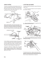
BURNER
PILOT
BURNER
HOLES
FLASH TUBE
VENTURI
ORIFICE HOOD
Once a valve is turned on, gas flows through the
orifice into the venturi and on to the burner, this
assembly simply slides over the orifice hood.
As gas flows into the burner, air is drawn into the
shutter to provide primary air for the proper air/gas
combustion ratio as explained in basics. As the gas
reaches the burner head, it will begin to flow through
the holes in the side of the burner head and into the
flash tube. Gas flows through the flash tube and is
then ignited by the standing pilot or ignitor. As this
gas is ignited, it flashes back through the tube and
ignites the burner.
9
OVEN SYSTEM
LIGHTING the RANGE
The oven is controlled by the thermostat valve. The
valve is mounted to the manifold. From the valve are
gas lines to the oven burner and one line to the pilot.
A small amount of gas flows through this valve
constantly for the oven standing pilot.
To light and adjust standing pilot ranges, follow these
simple steps.
1. Be sure all control knobs are in the OFF position
and raise the cooktop.
AIR SHUTTER
ORIFICE
OVEN
BURNER
MERCURY SENSING
BULB
PILOT
GAS SAFETY
VALVE
OVEN THERMOSTAT
VALVE
MANIFOLD
When the thermostat is set two things happen. First,
gas flows through the thermostat to the safety valve
at the burner. Secondly, whenever the thermostat is
set and the thermostat bulb is calling for heat, the gas
flow will increase to the pilot, causing a heater pilot.
2. Place a lighted match near the opening of the
pilot between the two burners.
ADJUSTMENT
SCREW
PILOT
GAS LINE
CONSTANT PILOT FLAME
HEATER PILOT
FLAME
FLAME
DEFLECTOR
MERCURY-FILLED
BULB
3. Adjust the pilot adjustment screw so the pilot
flame tip is 1/4" to 3/8" high and centered in the hole
in the pilot housing.
A flame deflector spreads the heater pilot flame over
a mercury-filled bulb. After this bulb is heated, it will
cause the safety valve to open. The safety valve will
then open and allow gas to flow to the oven burner.
The burner is then ignited by the heater pilot.
The burner continues to operate until the preset
temperature in the oven is reached. Once temperature is reached the heater pilot is reduced to the
regular standing pilot flame until the thermostat
again calls for heat.
To light the oven burner, make sure the oven is OFF.
Remove the oven racks. Hold a lighted match to the
opening in the top of the pilot at the rear of the oven
burner. No pilot adjustments are required.
10
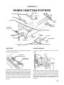
CHAPTER 4
SPARK IGNITION SYSTEMS
FLASH TUBE
TOP BURNERS
AIR SHUTTER
VENTURI
ORIFICE HOOD
CONTROL
KNOBS
IGNITOR
SWITCHES
PRESSURE
REGULATOR
TOP BURNER VALVE
OVEN
IGNITOR
SPARK
MODULE
IGNITOR
SHUTTER
MANIFOLD
OVEN
THERMOSTAT
PILOT/HEATER
PILOT
OVEN BURNER
SAFETY VALVE
ORIFICE HOOD
IGNITORS
SPARK MODULE
Instead of standing pilots to ignite the top and oven
burners you have ignitors.
The Spark module is mounted on the rear of the
range.
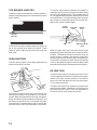
TOP BURNER
IGNITOR SWITCHES
THERMOSTAT
IGNITOR SWITCH
SPARK
MODULE
These ignitors are controlled by switches that are on
each burner valve and the thermostat valve. These
switches are rotary actuated and simply slide over
the valve stem and snap on the valve. Turning on a
burner valve to lite or setting the thermostat closes
the switch, making a circuit to the spark module.
They are normally open switches and are wired in
parallel.
IGNITOR
CABLE
Whenever the spark module is energized by one
of the switches through an ignitor cable, a solid-state
circuit and pulse transformer within the module
electronically sends pulses to “ALL” of the ignitor
electrodes at the same time. No adjustments can be
made to the module and it is serviced only as an
assembly.
11
TOP BURNER IGNITORS
The burner ignitors are basically a metal rod with a
ceramic insulating body which is wired directly to the
spark module.
The ignitor stops sparking because the module is
sending a sensing current through the ignitor along
with the high-voltage pulses. There is about 1/10" of
an inch gap between the ignitor electrode and the tab
on the pilot flame. The high-voltage pulses "jump the
gap" to ground, creating the spark, but the low voltage current cannot bridge the gap.
SPARK
IGNITOR
CONSTANT
PILOT
HEATER
PILOT
BURNER
BURNER
SUPPORT
IGNITOR
Pulses from the spark module cause the ignitors to
arc to the ground strap above the ignitor. These
pulses or sparks light the top burners through the
flash tube.
OVEN IGNITORS
The oven burner ignitor has a larger electrode and
sparks to the tab on the pilot.
TAB
MERCURY-FILLED
BULB
When the pilot does light, the flame fills the gap
between the ignitor electrode and the ground tab on
the pilot. The flame is actually a conductor due to its
carbon content. Therefore, the sensing current will
pass through the pilot flame to ground, completing a
circuit back to the spark module. When this sensing
circuit is completed, the ignitor module is deactivated
and stops sending high-voltage pulses to the ignitors.
RE-IGNITION
OVEN
IGNITOR
Unlike the surface burners which are manual, the
oven ignition system is an automatic or a re-ignition
system. When the thermostat knob is set, the ignitor
switch activates the spark module and ignitors, and
gas flows to the pilot burner. The ignitor will spark
until the pilot is ignited and then stop. The pilot will
continue to burn until the thermostat is turned off.
12
If the pilot should go out, the sensing current circuit
is interrupted by the loss of the flame, and the spark
module will begin sending pulses to the ignitors
which will continue sparking until the pilot lights.
This is called re-ignition.
The rest of the oven burner system is the same as the
standing pilot models. Remember in this system, the
pilot will continue to burn until the thermostat is
turned off, which shuts off gas to the pilot.
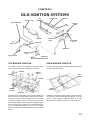
CHAPTER 5
GLO IGNITION SYSTEMS
ORIFICE SPUD
FLASH TUBE
TOP
BURNERS
VENTURI
ORIFICE BURNER
CONTROL
KNOB
AIR
SHUTTER
BROILER
AIR
SHUTTER
ORIFICE
HOOD
TOP BURNER
VALVE
GAS VALVE
MANIFOLD
SHUT-OFF
VALVE
ORIFICE HOOD
PRESSURE
REGULATOR
TOP BURNER IGNITION
OVEN BURNER IGNITION
The ignition switch is connected to a cam bar which
sits on top of the burner valves and manifold.
The oven burner system is slightly different than the
previous oven discussed.
CAM BAR
CAMS
IGNITOR
SWITCH
OVEN
BURNER
BURNER
OVEN
IGNITOR
BURNER
VALVES
MANIFOLD
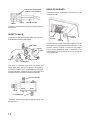
On each burner valve shaft, there is a cam. When the
control knob is turned the cam rotates with the shaft
of the burner valve. Once the control knob is turned
to the lite position, the cam will slide the cam bar
actuating the ignitor switch and then completing the
circuit to the ignitor module. This system functions
just like most gas ranges with top burner spark
ignition, except it only has one ignitor switch instead
of four.
Instead of a standing pilot or spark ignition system
this system uses a carbide glo type ignitor. This glo
ignitor, when voltage is applied, heats to a high
temperature to ignite the gas in the main burner.
13
IGNITOR MUST BE INSERTED
AGAINST STOPS IN SHIELD
BROILER BURNER
The broiler burner or blanket-of-flame burner is an
infrared burner.
IGNITOR
SHIELD
CERAMIC HOLDER
The ignitor is quite brittle so care must be used when
servicing it.
SAFETY VALVE
In series with the ignitor is the safety valve which is
located behind the storage drawer.
AMP-CLAMP
IGNITOR
MIN. 3.2 AMPS
FUSE
SAFETY VALVE
THERMOSTAT
The valve is a bimetal type valve that opens and
closes electrically. When the ignitor is energized it
will draw 3.2 amps. This 3.2 amperage draw is enough
to cause a bimetal, inside the valve, to warp open and
allow gas to flow to the burner being operated.
TO BROIL BURNER
BROIL
BAKE
BROIL
BAKE
GAS IN
TO OVEN BURNER
The safety valve supplies gas to both the broil and
bake burners.
14
OVEN
IGNITOR
BROIL
BURNER
BROIL
IGNITOR
This burner has no gas input adjustment since the
infrared burner is equipped with a fixed orifice. There
is no air shutter to adjust. The burner may have a
hazy or fuzzy appearance when in operation. This
haze may be 3/8" thick, maximum and is normal for
this type burner.
CHAPTER 6
GAS CONVERSION
NATURAL to LP GAS CONVERSION
Input ratings shown on the rating plate (serial tag)
are for elevations up to 2,000 feet. For elevations
above 2,000 feet, ratings should be reduced at a rate
of 4% for each 1,000 feet above sea level.
Most all ranges are pre-adjusted from the factory for
operation on “NATURAL” gas. To use the appliance
on “LIQUEFIED PETROLEUM” (LP)gas, the following four things must be done.
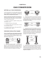
1. Change the pressure regulator setting from
“NATURAL” to “LP”.
CAP
SPRING
NAT. GAS
LP GAS
2. Remove the cap with the screwdriver slot and
turn it upside down. This cap will have the marking
“LPG10” shown. Be sure not to disturb or remove the
spring beneath this cap. Insert the cap in the body of
the regulator and tighten.
CAP
2. Readjust the burner orifice hoods.
INSERT
3. Change the select-a-gas screw which is on the
oven thermostat control.
4. Change the broil burner orifice spud (SELFCLEANING MODELS ONLY).
PRESSURE REGULATOR CHANGE
There are five different types of pressure regulators
that are used on ranges. Use the following as a guide
to convert your pressure regulator over to “LP” gas.
IN ANY CONVERSIONS, DO NOT REMOVE THE
PRESSURE REGULATOR.
SPRING
NAT. GAS
LP GAS
3. Remove the cap with the screwdriver slot. Now
remove the black insert marked “NAT.” from the cap.
Reverse this insert and carefully push it firmly into
the hole in the cap. The marking “LP” will now be
showing on the insert. Also, be sure not to disturb the
spring in the body of the regulator. Insert the cap in
the body of the regulator and tighten.
CAP
SPRING
CAP
WASHER
WASHER
SPRING
SPRING
NAT. GAS
LP GAS
1. Remove the cap marked “NAT.” and reverse it to
read “LP.” Be sure not to disturb or remove the spring
beneath the cap. Also make sure the fiber washer is
between the cap and the body of the regulator. Insert
the cap in the body of the regulator and tighten.
NAT. GAS
LP GAS
4. Remove the cap with the screwdriver slot. Now
remove the spring and washer (washer will be at
bottom of spring). Reverse these so that the washer is
now at the top of the spring, then reinstall. Insert the
cap over the washer and spring in the body of the
regulator and tighten.
15
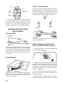
SELECT-A-GAS SCREW
CAP
SPRING
COVER
REGULATOR
SPRING
Remove the oven thermostat knob to be sure select-agas adjusting screw is in the proper position for the
type of gas being used. The select-a-gas screw is
located on the left side of the Robertshaw thermostat
and on the right side of the Harper thermostat.
LP
5. Use a wrench to unscrew the aluminum cap by
turning counterclockwise. Turn the cap over so the
hole end is up. Place the gasket between the cap and
regulator. Then place the cap and gasket on the
regulator and tighten. DO NOT OVERTIGHTEN.
BURNER ORIFICE HOOD
ADJUSTMENT
TOP BURNERS
NAT.
OFF
NAT.
LP
OFF
OFF
KNOB SHAFT
SELECTOR KEY
TOP BURNER
VALVE
AIR SHUTTER
ORIFICE HOOD
Remove the four top burner mounting screws, then
lift the burners off the brackets. Then screw the four
burner orifice hoods down till snug, approximately 2
to 2-1/2 turns. DO NOT OVERTIGHTEN. Burner
flames cannot be properly adjusted if this conversion
is not made.
Turn the screw clockwise to stop, for LP, and counterclockwise to stop, for NAT.
BROIL BURNER ORIFICE SPUD
(SELF-CLEANING MODELS ONLY)
1. Be sure the proper burner spud is selected for the
type of gas being used.
SCREWS
OVEN BURNER
2. Remove the two screws fastening the broil burner
assembly to the oven. Carefully pull the burner towards you, then downward to access the burner
orifice spud in the rear wall. Extra care is needed to
avoid breaking the ignitor coil. Place burner, screenside up, in a safe area.
OVEN ORIFICE
Screw the oven orifice hood down till snug, approximately 2 to 2 1/2 turns. DO NOT OVERTIGHTEN.
Burner flames cannot be properly adjusted if this
conversion is not made.
16
3. Use a nutdriver or wrench to remove the “NAT”
gas burner orifice spud. Install the selected “LP”
burner orifice spud.
4. Replace the burner assembly cover, making sure
the louvers are facing toward the rear of the range.
blank
blank