1
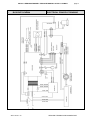
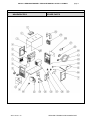
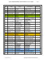
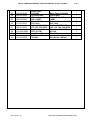
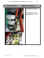
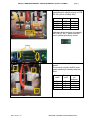
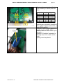
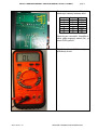
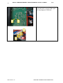
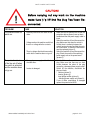
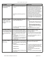
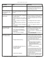
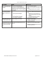
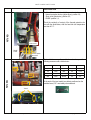
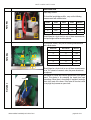
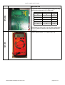
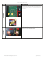
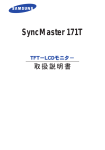
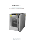
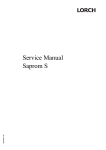
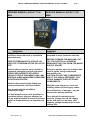
MG122-1 SERVISNÍ MANUÁL / SERVICE MANUAL ALFIN 171 W MAX
SERVISNÍ MANUÁL ALFIN 171 W
MAX
1.
VAROVÁNÍ
UPOZORNĚNÍ – Pouze osoba splňující
kvalifikaci danou zákonem je oprávněna
opravovat stroj.
PŘED OTEVŘENÍM KRYTU STROJE JEJ
ODPOJTE VYTAŽENÍM SÍŤOVÉ VIDLICE ZE
SÍTĚ.
Každé 4 měsíce otevřete stroj a jemně ho
vyfoukejte stlačeným suchým vzduchem
POZOR, NEPOUŽÍVEJTE STLAČENÝ
VZDUCH O PŘÍLIŠ VYSOKÉM TLAKU, ABY
NEDOŠLO K MECHANICKÉMU POŠKOZENÍ
ELEKTROSOUČÁSTEK.
Každé 4 měsíce zkontrolujte řádný stav
svařovacích kabelů a síťových kabelů.
Není povolena žádná modifikace
svařovacího stroje.
Pro Vaši bezpečnost je nutné posečkat se
sundáním krytu ze stroje po odpojení ze
sítě po dobu minimálně 5 minut, kdy klesne
napětí na kondenzátorech na hodnotu pod
36 V.
ALFA IN a. s. ©
page 1
SERVICE MANUAL ALFIN 171 W
MAX
WARNING
NOTE Only trained personnel are
permitted to work inside the machine.
BEFORE OPENING THE MACHINE, CUT
OFF ITS ELECTRICAL POWER BY
REMOVING THE PLUG FROM THE MAINS
SUPPLY SOCKET.
Every six months, open the machine and
clean it inside, using compressed
dehumidified air.
CAUTION. DO NOT USE COMPRESSED
AIR AT TOO HIGH A PRESSURE. YOU
COULD DAMAGE THE ELECTRONIC
COMPONENTS.
With the same frequency, check the
welding cables and the supply cables.
No modification, of any type, may be
made to the welding machine.
For safety while maintaining the
machine, please shut off the supply
power and wait for 5 minutes, until
capacity voltage already drops to safe
voltage 36V.
SERVISNÍ TECHNICKÁ DOKUMENTACE
MG122-1 SERVISNÍ MANUÁL / SERVICE MANUAL ALFIN 171 W MAX
2.
BLOKOVÉ SCHÉMA
ALFA IN a. s. ©
page 2
ELECTRICAL PRINCIPLE DRAWING
SERVISNÍ TECHNICKÁ DOKUMENTACE
MG122-1 SERVISNÍ MANUÁL / SERVICE MANUAL ALFIN 171 W MAX
3.
NÁHRADNÍ DÍLY
ALFA IN a. s. ©
page 3
SPARE PARTS
SERVISNÍ TECHNICKÁ DOKUMENTACE
MG122-1 SERVISNÍ MANUÁL / SERVICE MANUAL ALFIN 171 W MAX
Pos.
Code
1
2
3
011.0006.0031
011.0000.0115
041.004.0300
4
5
012.003.0000
050.001.0008
5
050.R01.0008
6
044.003.0002
7
011.0003.0003
8
012.003.0150
9
711P001204
10
3475
11
011.003.0001
12
13
2379-B
050.5026.9900
13
050.5R26.9900
14
050.001.0013
15
16
17
044.004.0001
042.003.0005
015.0001.0005
18
032.002.0255
19
050.001.0012
20
040.003.1070
21
050.001.0009
21
050.R01.0009
22
032.001.3506
ALFA IN a. s. ©
Popis
Držák - madlo
A171W
Kryt horní A171W
Hallova sonda Alfin
Držák vnitřní
160/200
PCB silová A160E
PCB silová A160E
REPAS
Cívka start HF
A160/200
Description
page 4
Quantity
Holder A171W
Upper cover A171W
Hall Sensor Alfin
1
1
1
Inner Support 160/200
PCB Power A160E
PCB Power A160E
REPAIR
2
1
Coil Start HF A160/200
Power Board
Deska ochranná
Protection Plate
A171W
A171W
Panel přední
Front Panel
Alfin160/200T
Alfin160/200T
Rychlosp. TEB 35Quick Connector 35-70
70 panel samice
Panel Socket
Sada kon. ALFIN
Connector Set ALFIN
G1/4 komple
G1/4 komple
Kryt spodní
Cover Lower
Alfin160/200
Alfin160/200
Knoflík21N6+modrá Knob21N6+Blue
krytka,podl.
Cover,Washer
PCB řídící A171W
PCB Kontrol A171W
PCB řídící A171W
PCB Kontrol A171W
REPAS
REPAIR
PCB odrušovací
A160T/200T
PCB Filter A160T/200T
Tlumivka
Alfin160/200
Choke Alfin160/200
Trafo Alfin160
Transformer Alfin160
Chladič A171W
Heat Sink A171W
Usměr. výstupní
Alfin
Rectifier Outlet Alfin
PCB RC-člen
PCB RC Circuit
A160E/200E
A160E/200E
Termostat
Thermostat
Alfin160/200
Alfin160/200
PCB HF Start
PCB HF Start
A160T/200T
A160T/200T
PCB HF Start
PCB HF Start
A160T/200T REPAS A160T/200T REPAIR
Usměr. vstupní
Alfin160
Rectifier Inlet Alfin160
1
1
1
1
2
1
1
1
1
1
1
1
1
1
2
1
1
1
1
1
SERVISNÍ TECHNICKÁ DOKUMENTACE
MG122-1 SERVISNÍ MANUÁL / SERVICE MANUAL ALFIN 171 W MAX
23
24
012.003.0100
045.000.0001
25
045.002.0001
26
017.001.5512
27
040.001.0010
28
29
013.0005.0000
003.002.0001
30
011.003.0002
ALFA IN a. s. ©
Panel zadní
A160/200
Vývodka Alfin
Kabel přívodní
Alfin 140ET
Ventil 24V DC
D=2,7mm
Vypínač Alfin 160,
170, 180, 200 HF25
Panel zadní ONOFF A171W
Ventilátor Alfin
Držák ventilátoru
160/200
page 5
Back Panel A160/200
Outlet Alfin
Mains Cable Alfin
140ET
Solenoid Valve 24V DC
D=2,7mm
Switch ON/OFF Alfin
160, 170, 180, 200 HF25
Rear Panel ON-OFF
A171W
Fan Alfin
1
1
Fan Holder 160/200
1
1
1
1
1
1
SERVISNÍ TECHNICKÁ DOKUMENTACE
MG122-1 SERVISNÍ MANUÁL / SERVICE MANUAL ALFIN 171 W MAX
4.
KONTROLA SILOVÉ PCB
page 6
CHECKING THE POWER PCB
Pozice kontaktů v konektoru
• teplotní čidlo (žluté dráty): pozice
3,6
Zkontrolujte spojení kontaktů
tepelné ochrany pomocí testeru
diod, teplota chladiče nesmí být
vyšší než 40° C.
ALFA IN a. s. ©
SERVISNÍ TECHNICKÁ DOKUMENTACE
MG122-1 SERVISNÍ MANUÁL / SERVICE MANUAL ALFIN 171 W MAX
page 7
Před kontrolou výstupních
usměrňovačů odpojte vývody k PCB
RC filtr (černé a hnědý drát)
červený
černý
hodnota
UP
MID
MID
DOWN
MID
UP
DOWN
MID
OL
>.150
>.150
OL
Nakonec zkontrolujeme dva transily
na PCB RC filtr. V obou směrech
musí vykázat přerušený obvod
Vstupní usměrňovač na silové
desce
Pro kontrolu můstku změřte tento
podle následující tabulky testerem
diod
ALFA IN a. s. ©
Červený
vodič
Černý
vodič
F+
D
D
F-
D
F+
FD
Naměře
ná
hodnota
OL
>0.450
OL
>0.450
SERVISNÍ TECHNICKÁ DOKUMENTACE
MG122-1 SERVISNÍ MANUÁL / SERVICE MANUAL ALFIN 171 W MAX
page 8
Pro kontrolu tranzistorů změřte tyto
podle následující tabulky testerem
diod
červený
D
S
G
S
G
D
černý
S
D
S
G
D
G
hodnota
OL
>.350
>1.5
>1.5
OL
OL
Hodnoty jsou orientační. Naměříte-li
zkrat, nebo rozpojený obvod (OL), je
nutné PCB vyměnit
Varistor je blízko vstupu napájecího
napětí na silovou PCB. Toto
zařízení slouží k ochraně PCB před
vstupním
přepětím. Při přepětí "exploduje" a
zkratuje vstup. Je-li rozsah zkratu
velmi
vysoký, obvod se přeruší
ALFA IN a. s. ©
SERVISNÍ TECHNICKÁ DOKUMENTACE
MG122-1 SERVISNÍ MANUÁL / SERVICE MANUAL ALFIN 171 W MAX
page 9
Pro kontrolu tranzistor změřte podle
následující tabulky testerem diod
červený
D
S
G
S
G
D
černý
S
D
S
G
D
G
hodnota
OL
>.350
OL
>0.5
OL
OL
Hodnoty jsou orientační. Naměříte-li
zkrat, nebo rozpojený obvod (OL), je
nutné PCB vyměnit
Digitální multimetr. "OL" označuje
přerušený obvod
ALFA IN a. s. ©
SERVISNÍ TECHNICKÁ DOKUMENTACE
MG122-1 SERVISNÍ MANUÁL / SERVICE MANUAL ALFIN 171 W MAX
page
10
Zkontrolujte testerem diod průchodnost
mezi body A/B na silové PCB a pinů
X/Y na propojce k PCB řídící.
ALFA IN a. s. ©
SERVISNÍ TECHNICKÁ DOKUMENTACE
170 T / 170 W / 171T / 171W
!"#$%&'(
)*+,-*( ./--0123( ,45( /20( 6,-7( ,2( 58*( 9/.812*(
'(
PROBLEM
The machine does not
switch on.
9/7*( :4-*( 15( 1:( ,++( /2;( 58*( <=43( 8/:( >**2( ;1:?
.,22*.5*;@(
CASE
!
Electrical power does not reach the machine.
SOLUTION
"!
"!
!
!
The protection devices
of the line set off when
the switch is activated
and the machine does
not go on.
!
!
Voltage reaches the machine switch but
there is no voltage after the contacts.
There is voltage after the disconnecting
switch but the machine does not go on.
Damaged power supply cable with shortcircuited wires.
Inverter is damaged.
Ultima modifica/ Last Modify: 03/11/2010 Rev1
"!
"!
"!
Make sure the line switches are closed, the
protection devices (fuses) have not been
enabled and that the power supply cable is
intact.
Switch the machine off and disconnect the
plug. Make sure that when the switch is
closed, there is continuity between the
contact input and output and that the varistor is not broken. In case the Power Board
must be replaced (picture 5).
Switch the machine off and disconnect the
plug. Check the mosfet of the switching
power supply unit on the power board
(picture 6).
Switch off the machine and disconnect the
plug. Make sure that there are no short
circuits between the poles of the plug
caused by a damaged power supply cable.
Switch off the machine, disconnect the
plug and check:
- varistors (picture 5);
- inverter (picture 4);
! Input bridge rectifier (picture 3);
!
switching power supply unit (picture 6).
If one of these components is damaged
replace the power board 0008.
pagina 11 di 19
170 T / 170 W / 171T / 171W
PROBLEM
The front panel does
not switch on.
CASE
!
!
The MMA/TIG output
voltage is about 14V
and the machine does
not weld.
!
!
The fan works but the front panel does
not go on.
Both the fan and the front panel do not
work.
The output voltage wiring of the front
panel is interrupted (picture 1).
The primary current alarm on the power
board is activated.
SOLUTION
"!
"!
"!
"!
Switch off the machine and disconnect the
plug. Make sure the flat cable that connects the front panel to the power board is
inserted correctly. If correctly inserted, replace the front panel. If the front panel
does not go on, one of the switching power
supply unit outputs is broken. Therefore
the power board must be replaced.
Switch off the machine, disconnect the
plug and check the mosfet of the switching
power supply unit on the power board. IF
it’s damaged it must be replaced (picture
6).
Switch off the machine and disconnect the
plug:
! Make sure that the wiring contact is correctly inserted in the connector (picture
1);
! Check for continuity between the +/output outlets and that the 6-path connector is connected to the front panel
(picture 1);
The power board must be replaced.
The output voltage in
each procedure is about
14V and enabling of the
thermal protection device.
Wait a few minutes keeping the machine on
to favour cooling of the inverter. If the machine continues running with the protection
devices on, switch the machine off and disconnect the plug. Remove the hood and
make sure:
! the temperature of the heat sink tool is
less than 40°C;
! If it is less than 40°C, check whether the
thermal protective device contacts are
normally closed.
The output voltage in
MMA is zero.
Switch the machine off and disconnect the Switch off the machine and disconnect the
plug. Check for a short circuit at the DINSE plug. Remove the snubber board:
plug with a diode tester. A short circuit may
be caused by :
! damaged transil on the snubber board;
"!
check with a diode tester the status of the
transil on the snubber board (picture 2);
! damaged diodes;
"!
check with a diode tester the status of the
diodes (picture 2);
"!
check the status of the power board
! damaged inverter;
(picture 4);
The Power Transformer must be replace.
! The inductive value of the Power Trans- "!
former is null.
Ultima modifica/ Last Modify: 03/11/2010 Rev1
- If one of the protection devices is always
opened it is defective, it must be
accordingly replaced.
- If it is closed, make sure the two terminals
are well inserted in the connector (picture
1).
- Power board feed problems, it must be
accordingly replaced.
pagina 12 di 19
170 T / 170 W / 171T / 171W
PROBLEM
CASE
The welding is non opti- Spattering occurs during welding.
mal.
SOLUTION
Make sure welding polarity is correct, the
earth clamp is fixed correctly and check the
hot-start and arc-force values that have to be
decreased if they are too high.
When welding the pro- Make sure the welding current does not Decrease the welding current.
require greater power than the one supplied
tection devices of the
by the line.
line set off.
The remote control
doesn’t work.
"!
"!
"!
"!
"!
The machine does not
strike in HF mode.
!
The front panel could be damaged.
"!
The damaged cable must be replaced.
"!
The potentiometer must be replaced.
"!
"!
!
!
Excessive gas pressure.
"!
!
Damage solenoid valve wiring.
"!
!
!
The solenoid valve control relay on the
front panel is damaged.
Feeding is missing.
!
Solenoid valve is damaged.
!
Ultima modifica/ Last Modify: 03/11/2010 Rev1
Insert the wires into the connectors correctly and insert the connectors into their
housings. Should this not be sufficient, replace the front panel board or the power
board.
"!
The HF board could be damaged.
HF board cable could be damaged or
disconnected.
The HF transformer is damaged.
!
Gas does not come out
from solenoid valve.
Make sure the wiring which goes to the
front panel board 0010 is connected to
the 6-pin connector.
Make sure that the 2-pin connector is
correctly connected to the power board
0008.
Check the continuity of the remote control cable.
The torch potentiometer could be damaged.
The amphenol connector is damaged or
disconnected.
"!
"!
"!
"!
"!
"!
Connect the amphenol connector or replace it.
Replace the front panel board; first verify
that the spare part has the right software.
The HF board must be replaced.
Connect the cables or, if damaged, replace
them.
The HF transformer could be damaged, in
case it must be replaced.
Remove the gas connection. Carry out a
gas test on the front panel in the TIG procedure and check opening of the solenoid
valve. Reduce gas pressure. Restore connections and carry out a gas test.
Switch off the machine and disconnect the
plug:
! Check the continuity of the solenoid
valve cable .If there’s no continuity, try
to repair the damaged cables;
! Check that the connectors are correctly
inserted.
The front panel must be replaced.
Check continuity between points A/B of the
power board and x/y poles of the connector that goes to the front panel. After that
the solenoid valve or the front panel must
be replaced (picture 8).
Should the operations carried out not have
a positive outcome, replace the solenoid
valve.
pagina 13 di 19
170 T / 170 W / 171T / 171W
PROBLEM
The torch button doesn’t work.
CASE
!
!
!
The machine always
welds at maximum current.
The torch could be damaged.
There is no continuity between the
amphenol connector and the front panel.
The front panel or the HF board are
damaged.
SOLUTION
"!
"!
"!
"!
!
!
!
The front panel is damaged.
The Power Board is damaged.
The Hall Effect is damaged.
Gas comes out but the Pre-gas settings are not correct.
machine doesn’t weld.
The machine can’t stop The slope up and slope down are not corwelding or the welding rectly set.
current is not the one
set.
Ultima modifica/ Last Modify: 03/11/2010 Rev1
"!
The Torch must be replaced.
Single out the interruption and replace the
wiring.
The damaged boards must be replaced.
Switch off the machine and disconnect the
plug:
!
Replace the front panel board; first
verify that the spare part has the right
software.
!
The Power Board must be replace.
The Hall Effect must be replace.
"!
Regulate pre-gas settings.
Otherwise, reset the parameters and reset
the machine (picture 9).
"!
Regulate in the correct way the slopes.
"!
"!
Otherwise, reset the parameters and reset
the machine (picture 9).
pagina 14 di 19
170 T / 170 W / 171T / 171W
EXPLANATION
Position of the connector in which they are inserted:
"!
thermal protection device (yellow wires): position 3,6;
"!
Short circuit (black wire): position 2,5;
"!
DINSE: position 1,4;
PICTURE 1
Check the continuity of contact of the thermal protection device with the diode tester, with the heat sink tool temperature
less than 40° C.
Short-circuit
DINSE
socket
Thermal protection device
To check diodes remove the snubber board and carry out the
following measures with a diode tester:
UP
PICTURE 2
MID
DOWN
Copper bar
Probe
Copper bar
Probe
Measure
UP
red
MID
black
“OL”
UP
black
MID
red
>.150
MID
red
DOWN
black
>.150
MID
black
DOWN
red
“OL”
At the ends of the two transils (see below) positioned on the
snubber board, “OL” must always be measured.
Transil
Ultima modifica/ Last Modify: 03/11/2010 Rev1
pagina 15 di 19
170 T / 170 W / 171T / 171W
EXPLANATION
Input bridge rectifier .
To check the Input bridge rectifier , carry out the following
measurements with a diode tester:
FPICTURE 3
D
D
F+
Faston
Probe
Faston
Probe
Measure
F+
red
D
black
“OL”
F
red
D
black
>.450
F+
black
D
red
“OL”
F-
black
D
red
>.450
Should there be a short circuit on one of these measurements,
the input bridge rectifier must be replaced.
PICTURE 4
To check the inverter, carry out the following measurements
with a diode tester:
GDS
GDS
GDS
Red Probe
Black Probe
Measure
D
S
“OL”
S
D
>.350
G
S
>1.5
S
G
>1.5
G
D
“OL”
D
G
“OL”
GDS
Should there be a short-circuit on one of these measurements
or an “OL” instead of a numeric value, the power board must
be replaced.
PICTURE 5
Varistor
Ultima modifica/ Last Modify: 03/11/2010 Rev1
The varistor is a blue disc near the ground wire of the power
board. This device is for protecting the board from input
overvoltage. When there is overvoltage it “explodes” causing a
short circuit most of the times. If the extent of the short circuit
is very high they become an open circuit.
pagina 16 di 19
170 T / 170 W / 171T / 171W
EXPLANATION
To check the mosfet of the switching power supply unit, carry
the following measurements with a diode tester:
PICTURE 6
G
D
S
Red Probe
Black Probe
Measure
D
S
“OL”
S
D
>.350
G
S
“OL”
S
G
>0.5
G
D
“OL”
D
G
“OL”
Should there be a short-circuit on one of these measurements
or an “OL” instead of a numeric value, the power board must
be replaced.
PICTURE 7
Tester or digital millimetre. “OL” means Open Loop.
Ultima modifica/ Last Modify: 03/11/2010 Rev1
pagina 17 di 19
170 T / 170 W / 171T / 171W
EXPLANATION
PICTURE 8
Check continuity, with a diode tester, between points A/B of
the power board and x/y poles of the connector that goes to
the front panel.
A
B
X
Y
PICTURE 9
In order to reset the parameters, switch the machine on while
the S3 and S5 buttons are being pressed.
S3
S5
Ultima modifica/ Last Modify: 03/11/2010 Rev1
pagina 18 di 19
MG122-1
SERVISNÍ MANUÁL ALFIN 171 W MAX
SERVICE MANUAL ALFIN 171 W MAX
Vypracoval:
Worked out:
DJ 24/1/2011
Přezkoumal:
Inspected:
DJ 7/11/2011
Schválil:
Approved:
DJ 7/11/2011