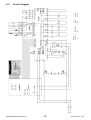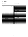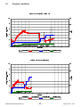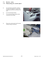
1
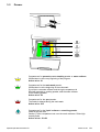
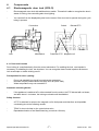
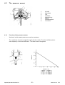
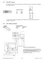
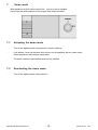
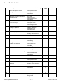
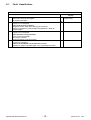
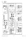
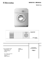
SERVICE MANUAL Washing Frontloading washing machines 599 51 57-87 EN Spares Operation HV844-N Edition: 03/2003 EWM 3000 LCD Index 1. 1.1 2. 2.1 2.2 3. 3.1 3.2 4. 4.1 4.1.1 4.2 4.2.1 4.3 4.4 4.5 4.6 4.7 4.8 5. 5.1 6. 6.1 7. 7. 7.2 7.1 7.2 8. 8.1 9. 9.1 9.2 9.3 10. 11. 11.1 11.2 Operation of the device .......................................................................................... 3 Control panel ......................................................................................................... 3 Aqua control system .............................................................................................. 4 General construction .............................................................................................. 4 Floating switch ....................................................................................................... 4 Water intake system .............................................................................................. 5 Waterdistributer + valves ....................................................................................... 5 Drawer ................................................................................................................... 6 Components .......................................................................................................... 7 Electromagnetic door lock (IDOLO) ....................................................................... 7 Door lock function .................................................................................................. 7 The pressure sensor ............................................................................................. 8 Function of the pressure sensor ............................................................................ 8 The NTC sensor .................................................................................................... 9 The heating element .............................................................................................. 9 The drain pump .................................................................................................... 10 The recirculation pump ........................................................................................ 10 The inlet valves .................................................................................................... 11 The motor ............................................................................................................ 11 Motor control (Puls width modulation) .................................................................. 12 Signals from the main electronic board to the motor electronic ........................... 12 Customer service program .................................................................................. 13 Activating the service program ............................................................................. 13 Demo mode ......................................................................................................... 14 Demo-Mode ......................................................................................................... 14 Deaktivieren des Demo-Modes ............................................................................ 14 Activating the demo mode .................................................................................... 14 Deactivating the demo mode ............................................................................... 14 Faultindication ...................................................................................................... 15 Fault classification ............................................................................................... 16 Technic ................................................................................................................ 17 Wiring ................................................................................................................... 17 Circuit diagram..................................................................................................... 18 Legend ................................................................................................................. 19 Program workflow ............................................................................................... 20 Service- notes ...................................................................................................... 21 Dismounting the control panel ............................................................................. 21 Dismounting the LCD operating part .................................................................... 22 1. Operation of the device - The appliance is provided with a control knob with integrated ON/OFF switch. Press down the control knob to switch the appliance on or off. - When you switch on, the control knob is extracted from its retracted position. For switching off, press the control knob back to its retracted position. Keys 1.1 Control panel LCD display Control knob 2. 2.1 Aqua control system General construction - Safty hose with a normal pressure hose inside, without integrated electrical connection between the machine and the water tab valve. - Hose system is all around closed and watertight - At the water tab is a mechanic safty valve without electric connection - The hose is connected at the water inlet valve - In case of a fault, that means the inner hose is leaking, a sponge as a part of the mechanic safty valve expands and closes the valve at the water tab. - The water inlet valve with a flow regulator is positioned in the machine. - There is no need for for special AC water distributer or valves. 2.2 Floating switch - Aqua-Control is generally with buzzer - There is no need for a special electronic concerning AC Floating switch f16 with 2 alternating contacts: - Switches on the pump - the pump has direct voltage. - Electronic recognizes the opened pump contact and therefore the AC- case. - The fault code C3 is shown. - At this position the program stops. - If the floating switches back the machine stops pumping. Spares Operation 02.2003 C.D. -4- 599 51 57-87 EN 3. 3.1 Water intake system Waterdistributer + valves - 4 detergent chambers; recirculation pump and drain pump 4- way waterdistributer 3 valves Spares Operation 02.2003 C.D. -5- 599 51 57-87 EN 3.2 Drawer Compartment for prewash powder/soaking powder or water softener Will be taken in at the very beginning of the program Active valve: S1 Compartment for the main wash powder. Will be taken in at the beginning of the main wash. If you like to use water softener and the right compartment is filled with prewash or soaking powder, add the water softener to the washing powder. Active valve: S2 Compartment for the spot powder. The intake is delayed during the main wash. Active valve: S15 Compartment for the liquid softener or starching powder Intake at the last rinse. Caution: Fill the compartment not over the mark maximum. Dilute high viscidity fluids. Active valves: S1+S2 Spares Operation 02.2003 C.D. -6- 599 51 57-87 EN 4. 4.1 Components Electromagnetic door lock (IDOLO) - Electromagnetic door lock with additional door switch. This switch is able to recognize the doors status of locking, thus controlling also drum lighting. - You can see from the displayed symbol on the screen if the door can be opened during the cycle being in process. Connection Lock Microswitch Switch Bimetal-PTC Protection-PTC Magnetic coil 4.1.1 Door lock function Door locking is controlled directly from the control electronics. For enabling the lock, one impulse is necessary, for disabling the lock, two impulses. You can recognize these control impulses at the door lock as a simple or double clicking sound. Prerequisites for door opening: - Drum is at standstill (no signal from tachometer generator) No water may be present above the lower door rim (level <fN2) Water temperature may not exceed 40°C. Automatic unlocking device: - if the appliance is switched off or disconnected from the mains, the PTC bimetal will cool down, and after about 1-4 minutes, the locking mechanism will be disabled. Safety function: - A PTC is switched in series to the magnetic coil to limit power and therefore avoid possible overheating due to the following causes: - TRIAC is short-circuited on the control electronics Repeated activation of the Start/Pause key (more than 10 times) Spares Operation 02.2003 C.D. -7- 599 51 57-87 EN 4.2 The pressure sensor 1 2 3 4 5 6 7 8 Air inlet Membrane Coil Oscillator Magnetic ring Spring Screw to adjust Connector 4.2.1 Function of the pressure sensor - Via the air inlet the water pressure moves the membrane. - The membrane moves the magnetic ring (5) into the coil (3). Then the oscillator puts an other frequency on the main electronic. The water level is recognized. Spares Operation 02.2003 C.D. -8- 599 51 57-87 EN 4.3 The NTC sensor The electronic controls the drain temperature by a NTC temperature sensor which is integrated in the heating element. NTC-sensor f30: °C W 20 6050 60 1250 80 640 - To check the NTC sensor functionality you can measure the ohmic resistance between the contacts T2/1 and T2/2. 4.4 The heating element Heating element: Connection: 230V; 50 Hz; Power: 1950W Fuse: 10A Control of heating element (r1): In order to heat, the dry-running protection level (fTR1,fTR2) must be achieved. The heating relay K3 on the electronic has to be closed. The appliance must be switched on (b7/DW) and the door locked (e4). Spares Operation 02.2003 C.D. -9- 599 51 57-87 EN 4.5 The drain pump Drain pump: Connection: Flowrate: Power: Resistance: 230 V; 50 Hz; synchron 22 l/min 34 W +30% 164W +5/-5% Pump control (m3): In order to pump, the appliance must be switched on (b7/DW), the safety level and the floating switch have to be in empty position. The electronic controls the pump by a triac, depending on the program. In case of aqua control the floating switch is in full position and the drain pump is active until the plug is pulled or the water is removed out of the bottom tray. The appliance would even pump when the appliance is switched on and the safety level (fS) has reacted. Over-filling protection! 4.6 The recirculation pump Recirculation pump: Connection: 230 V; 50 Hz; synchron Flowrate: 25 l/min Power: 22 W +30% Resistance: 202W +5/-5% Recirculation pump control (m22): The recirculation pump is powerde by a triac located on the main electronic board depending on the program cycle. Spares Operation 02.2003 C.D. - 10 - 599 51 57-87 EN 4.7 The inlet valves Inlet valve: Connection: Pressure: Flowrate: 220/240V +6-15%; 50 Hz; 0,6 10 bar 8 l/min Inlet valves (s1,s2,s15): The valves are powered by a triac located on the main electronic board depending on the program cycle. 4.8 The motor Tachogenerator Stator Rotor Relay for direction of movement Relay tapping field MOS-FET transistor to mainboard Sachnummer Anschlusswert Tacho (3-4) Rotor (8-9) Stator (5-1) Stator komplett (5-10) 110 536 1.. FHP 110 536 4.. FHP 230V; DC 230V; DC 223W +/-8% 223W +/-8% 1,45W +/-8% 1,45W +/-8% 1,00W +/-8% 2,50W +/-8% 2,50W +/-8% Spares Operation 02.2003 C.D. - 11 - 599 51 57-87 EN 5. Motor control (Puls width modulation) - The motor is controlled with a pulsing DC, frequency 16kHz. - The revolution is controlled with the switch on- and off time of the DC. - Smallest possible switch-off time is 2 %. I/U T t in s T=1/16000 5.1 Signals from the main electronic board to the motor electronic Voltage input Main electronic Motor electronic Code for direction of drum movement and tapping field PTC temperature check 13V for Relay Spares Operation 02.2003 C.D. - 12 - 599 51 57-87 EN 6. Customer service program 1 2 S1 6.1 Activating the service program - Turn the appliance off with the Control Knob S1 (retracted position). - Press simultaneously keys 1 and 2 and switch the appliance on with the Control Knob. Keep both keys pressed until the Service Program appears in the display. - To select the different service functions, regulate the control knob to the desired position, as when selecting a wash cycle. 7HVWIXQFWLRQ $/$50&2'(&/($5 /DVWHUURUFRGHRFFXUUHGZLOOEHFOHDUHGGRZQ 1RWDVVLJQHG 1RWDVVLJQHG 1RWDVVLJQHG 1RWDVVLJQHG /&'7(67 'LVSOD\7HVW /$1*8$*( /DQJXDJH '5$,1 (YDFXDWLRQ +($7,1*:/ :DWHULQWDNHYLDPDLQZDVKFRPSDUWPHQWXSWRI1KHDWLQJXS WR&UHFLUFXODWLRQSXPS21UHYHUVLQJ $/$50&2'(5($' /DVWHUURUFRGHRFFXUUHGZLOOEHGLVSOD\HG :/0$,1:$6+ :DWHULQWDNHYLDPDLQZDVKFRPSDUWPHQWXSWRI6 1RWDVVLJQHG :/62)7(1(5 :DWHULQWDNHYLDVRIWHQHUFRPSDUWPHQWXSWRI6 1RWDVVLJQHG 1RWDVVLJQHG :/35(:$6+ :DWHULQWDNHYLDSUHZDVKFRPSDUWPHQWXSWRI6 :/0$,1:$6+ :DWHULQWDNHYLDPDLQZDVKFRPSDUWPHQWXSWRI6 :/67$,1 :DWHULQWDNHYLDVWDLQFRPSDUWPHQWXSWRI6 5// 5HYHUVLQJ 63,1&203/),(/' 6SLQGU\ZLWKFRPSOHWHILHOGSRVVLEOHRQO\DIWHUHYDFXDWLRQ 1RWDVVLJQHG 63,1+$/)),(/' 6SLQGU\ZLWKSDUWLDOILHOGSRVVLEOHRQO\DIWHUHYDFXDWLRQ Spares Operation 02.2003 C.D. - 13 - 599 51 57-87 EN 7. Demo mode With appliances as from serial number 306 a demo mode is available. In this mode the setting options and a program flow will be simulated. 1 S1 4 7.1 Activating the demo mode - Turn off the appliance with rotary switch S1 (sunk-in position). - Push buttons 1 and 4 at the same time and turn on the appliance with the rotary switch. Hold both buttons until the demo mode starts. - The demo mode runs automatically and cant be modified. 7.2 Deactivating the demo mode - Turn off the appliance with rotary switch S1. Spares Operation 02.2003 C.D. - 14 - 599 51 57-87 EN 8. Faultindication 7\SHRI)DXOW 3URFHGXUHZLWKIDXOWILQGLQJ &ODVVLIL FDWLRQ 7LPH 6 6 6 6 FKHFNSUHVVXUHVHQVRU FKHFNSUHVVXUHVZLWFK FKHFNZLULQJ FKHFNKHDWLQJ FKHFNKHDWLQJUHOD\ FKHFNSUHVVXUHVZLWFK FKHFN17& FKHFNZLULQJ FKHFN17& FKHFNZLULQJ 6 ( ( FKHFNGULYHPRWRU FKHFNFDUERQEUXVKHV FKHFNWDFKRJHQHUDWRU FKHFNZLULQJ H[FKDQJHPRWRUHOHFWURQLF ( 6 FKHFNLQOHWYDOYHV FKHFNSUHVVXUHVZLWFK FKHFNZLULQJ FKHFNZLULQJ H[FKDQJHPRWRUHOHFWURQLF ( 6 6 ( 6 ( & LQFRQJUXHQFHEHWZHHQSUHVVXUH VHQVRUDQGSUHVVXUHVZLWFK KHDWLQJHOHPHQWGHIHFWLYH FKHFNKHDWLQJHOHPHQW FKHFNSUHVVXUHVZLWFK FKHFNSUHVVXUHVHQVRU FKHFNZLULQJ & QRZDWHULQOHW YDOYHGRHVQRWRSHQLQWHUUXSWLRQ IORZUDWHWRRORZ & SXPSEORFNHGGRHVQRWIXQFWLRQ SXPSLQWHUUXSWLRQ UHGXFHGGHOLYHU\ & DTXDFRQWUROKDVUHVSRQGHG OHDNDJHLQDSSOLDQFH & FLUFXODWLRQSXPSGHIHFWLYH & FKHFNZDWHULQOHW FOHDQVLHYH FKHFNLQOHWYDOYH FKHFNSUHVVXUHVHQVRU FKHFNZLULQJ FKHFNSXPS FKHFNGUDLQV\VWHP FKHFNSUHVVXUHVHQVRU FKHFNSUHVVXUHVZLWFK FKHFNZLULQJ KRVHVFUHZLQJOHDN\ OHDNDJHLQDSSOLDQFH FKHFNGUDLQSXPS FKHFNIORDWVZLWFK FKHFNZLULQJ FKHFNFLUFXODWLRQSXPS FKHFNZLULQJ H[FKDQJHPDLQHOHFWURQLF & SUHVVXUHVHQVRUGHIHFWLYH SUHVVXUHVZLWFKGHIHFWLYH & KHDWLQJHOHPHQWGHIHFWLYH KHDWLQJUHOD\GHIHFWLYH & 17&GHIHFWLYH & WDFKRPHWHULPSXOVHVDUHPLVVLQJ &$ 026)(7WUDQVLVWRUGHIHFWLYH &% [VDIHW\OHYHO && 37&IRU026±)(7WUDQVLVWRU GHIHFWLYH &' GRRUORFNGHIHFWLYH FKHFNGRRUORFN FKHFNZLULQJ &( &) FKHFNVXPIDXOW((3520 ZURQJLRRUPDLQHOHFWURQLF XSGDWHIDXOW\ ZURQJXSGDWH Spares Operation 02.2003 C.D. - 15 - 6 599 51 57-87 EN 8.1 Fault classification &RPSRVLWLRQRI$ODUP&RGHV &ODVVLILFDWLRQ )DXOWFRGHLVQRWLQGLFDWHG )DXOWFRGHLVVDYHGLQIDXOWUHJLVWHU 1RSURJUDPLQWHUUXSWLRQ )DXOWFRGHLVLQGLFDWHG 3URJUDPUXQLVLQWHUUXSWHG )DXOWFDQEHUHVHWE\FXVWRPHU 6WDUWSDXVHEXWWRQUHVHWVDODUPDQGSURJUDPFRQWLQXHV 6ZLWFKLQJRIIDSSOLDQFHUHVHWVWKHDODUPDQGDSSOLDQFHLVUHDG\IRU RSHUDWLRQDJDLQ )DXOWFRGHLVLQGLFDWHG 3URJUDPUXQLVLQWHUUXSWHG )DXOWFDQQRWEHUHVHWE\FXVWRPHU $ODUPLVUHVHWDXWRPDWLFDOO\ ZKHQIDXOWLVUHPRYHG 6WDUW3DXVHEXWWRQFRQWLQXHVSURJUDP )DXOWFRGHLVLQGLFDWHG 3URJUDPUXQLVVWRSSHG )DXOWFDQEHHOLPLQDWHGRQO\E\DIWHUVDOHVVHUYLFH $SSOLDQFHLVUHDG\IRURSHUDWLRQDJDLQRQO\E\DFWLYDWLQJWHVWURXWLQH Spares Operation 02.2003 C.D. - 16 - 7LPHRI,QGLFDWLRQLQWKH GLVSOD\ 6 LPPHGLDWHO\ SURJUDPVWRSV ( DWWKHF\FOHHQG 3 RQO\LQWKHWHVWURXWLQH 599 51 57-87 EN 9. 9.1 Technic Wiring Spares Operation 02.2003 C.D. - 17 - 599 51 57-87 EN - 18 - S2 S1 S15 Mainwash Valve Prewash Bleach Spares Operation 02.2003 C.D. S1+S2 Circuit diagram Softener 9.2 599 51 57-87 EN 9.3 Legend Legend wiring plan Legend circuit diagram b7 / DW Selection switch e4 Door lock E Main electronic f16.1 f16.2 Floating switch f 30 NTC - Sensor fS Safety level fTR1 ; fTR2 Boil-dry protection g1 Tacho generator h11 Lamp k1 Direction of drum movement k2 k3 Tapping / complete field PWM k5 Suppressor Pressure switch fs;fTR2;fTR1 m1 Main motor N Pressure sensor p m3 Drain pump P Recirculation pump m22 m22 Recirculation pump P Pump m3 p Pressure sensor R Heating r1 r1 Heating element V Valve s1;s2;s15 s1 s2 s15 Valve Z Door lock e4 s17 In / Output electronic Short name A Description Connection housing C Selection switch b7/DW E NTC - Sensor f30 E Main electronic F In / Output electronic S17 H Lamp h11 HE Main earth K Suppressor k5 L Floating switch f16.1 ; f16.2 M Motor m1 M Motor electronic N Spares Operation 02.2003 C.D. Description in the wiring plan - 19 - 599 51 57-87 EN 10. Program workflow (1(5*<6$9(3URJUDPPHZLWK:$6+ \ J U H Q H S P H W H \ O U H W D G H H S 6 : 7LPH>PLQ@ 'UHK]DKO>USP@ 7HPSHUDWXU>&@ :DVVHU]XODXI>OWU@ (QHUJLH>N:K@ 3URJUDPP'(66286PLW:lVFKH H L J U H Q ( S P H W Q H J X D / U H V V D O K D ] K H U ' : =HLW>PLQ@ 'UHK]DKO>USP@ Spares Operation 02.2003 C.D. 7HPSHUDWXU>&@ :DVVHU]XODXI>OWU@ - 20 - (QHUJLH>N:K@ 599 51 57-87 EN 11. 11.1 Service- notes Dismounting the control panel a) The countertop is fixed with 2 screws to the back of the appliance. Unscrew both screws and remove the countertop to the back. b) Pull out the detergent drawer. c) Turn out the two upper screws and the screws behind the drawer. d) Remove the control panel to the front and unplug the plug-in connectors. Spares Operation 02.2003 C.D. - 21 - 4 screws 599 51 57-87 EN 11.2 Dismounting the LCD operating part e) The LCD operating part is fixed to the face with 6 screws. Unscrew the screws and lift the operating part off upward. f) Press the two side fastening lugs slightly apart, and lift the operating part off. g) The operating face is locked with 2 fastening lugs at the top, and at the bottom, with 3 fastening lugs. 6 screws 2 fastening lugs Unlock the fastening lugs and remove the control face along with keys. You can now take off the keys and unplug the control knob. Spares Operation 02.2003 C.D. - 22 - 599 51 57-87 EN