1
SERVICE MANUAL
DISHWASHER
+ EDW 1003
Dishwasher
© Electrolux
Muggenhofer Straße 135
D-90429 Nürnberg
Germany
Fax +49 (0)911 323 1022
Spares Operation
Ausgabe:
09.02
R.Kurzke
Publ.-Nr.:
599 515 183
EN
+
EDW 1003
Index
1.
Control panel ................................................................................... 3
2.
Dimensions ...................................................................................... 3
3.
3.1
3.2.
3.3
3.4
3.5
3.6
3.7
3.8
3.9
3.10
3.11
3.11.1
Components .................................................................................... 4
Electronic ......................................................................................... 4
Circulation pump ............................................................................. 4
Drain pump ...................................................................................... 4
Flow heater ...................................................................................... 4
Detergent dispenser ........................................................................ 5
NTC-thermal sensor ........................................................................ 6
Pressure switch ............................................................................... 6
Interference filter ............................................................................. 6
Spray arms ...................................................................................... 7
Drying fan ........................................................................................ 7
Regeneration dosing with condensor ............................................. 8
Water softening/regeneration ......................................................... 8
4.1
4.2
Repair informations ......................................................................... 9
Open the housing ............................................................................ 9
Position of the components ............................................................ 10 - 12
5.1
5.2
5.2.1
5.3
Water course Scheme .................................................................... 13
All-Around Water Protection ........................................................... 14
Water intake .................................................................................... 15
Water load steps ............................................................................. 16 - 17
Draining ........................................................................................... 18 - 19
6.1
6.2
6.3
6.4
6.5
6.6
6.7.1
6.7.2
6.8
6.9
6.10
6.11
6.12
6.13
6.14
6.15
6.16
6.17
Electronic ......................................................................................... 20
In- and Output Elements ................................................................. 20
General information ........................................................................ 21
Input-philosophy: Program selection .............................................. 22
Input-philosophy: Select start time .................................................. 23
Input-philosophy: Program sequence ............................................. 24
Input-philosophy: delete program ................................................... 25
Input-philosophy: alter program ...................................................... 26
Input-philosophy: alter program ...................................................... 27
Input-philosophy: interrupt program ................................................ 28
Input-philosophy: Displays .............................................................. 29
Overview of customer and aftersales service functions ................. 30
Servicefunction / Adjust water hardness ........................................ 31
Deactivation of rinse-aid addition .................................................... 32
Deactivation of signal sound ........................................................... 33
fault memory and single actuator selection .................................... 34
LED test with integrated deletion of the fault memory .................... 35
manufacturing test routine: ............................................................. 36
Overview of error displays............................................................... 37
8.1
8.2
Wirings ............................................................................................ 39
electric circuit diagram .................................................................... 39
Wiring diagramn .............................................................................. 40
4.
5.
6.
8.
09.2002 R.K.
-2-
599 515 183
EN
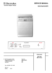
1.
Control panel
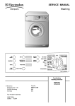
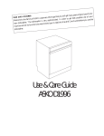
2.
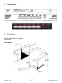
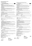
Dimensions
Build-in dimensions for Integrated
Dishwashers
ÖKO-FAVORIT
*
09.2002 R.K.
Appliances with height-adjustable feet
Plinth height for appliances 820 mm high
100 - 175 mm
Plinth height for appliances 870 mm high
150 - 230 mm
-3-
599 515 183
EN
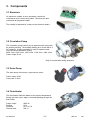
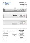
3. Components
3.1 Electronic
On electronic models, a micro processor controls all
components, this is done using triacs. The electronic also
memorizes all programme data.
The heating is switched by a relay on the electronic board.
3.2 Circulation Pump
The circulation pump is driven by an asynchronous motor with
an auxiliary winding. The auxiliary winding ist in circuit with a 3
mF capacitor. A tacho generator is used for speed control.
There are three speeds for rinsing.
2800 1/min, 2200 1/min, 1900 1/min, 1700 1/min, 1600 1/min,
Power output 50 W.
Only for models with ceiling spray arm
3.3 Drain Pump
The drain pump is driven by a synchronous motor.
Power output 26 W.
Pump rate 15 l/min.
3.4 Flow Heater
The flow heater heats the water to the required temperature.
During the wash cycle, water is contantly passing through the
flow heater.
Power output
Resistor
Protector
Thermal fuse
05.2002 R.K.
2000 W
25 W
98 °C ± 5 K
260 °C
-4-
599 514
DE
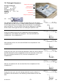
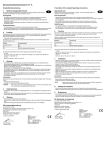
3.5 Detergent dispenser
Dosing of detergent
prewash
10 ml
wash
20 - 30 ml
Dosing of rinse aid
position 1 - 6
2 ml - 7 ml
Capacity
140 ml
display lack of rinse aid
dosing of rinse-aid
maximum filling level
outlet of rinse-aid
detergent tray
detergent tray for pre wash
coil
Spule
The detergent compartment 1 is filling corresponding to the set dosing
quantity when the door is open. Possibly existing rinse-aid in compartments
2 and 3 flows back into the storage tank of the rinse-aid. The detergent
trays are filled up. The door will be closed and the detergent for prewash
will be rinsed out through the slots in the detergent dispenser cover.
During the washing cycle the coil is switched on and the detergent
compartment cover releases the detergent. The rinse-aid flows from
compartment 1 into compartment 2.
EIN
AUS
Zeit
EIN
AUS
Zeit
EIN
AUS
Zeit
After switching off the coil, the rinse-aid flows from compartment 2 into
compartment 3.
During the rinse cycle, the coil will be switched on when the rinse is warmed
and the rinse-aid runs from compartment 3 into the rinse tank. At the same
time, the remaining rinse-aid (15 %) runs from compartment 1 into
compartment 2.
EIN
AUS
Zeit
EIN
AUS
Zeit
With the coil switched off, the rinse-aid flows from compartment 2 into
compartment 3.
During the rinse cycle, the coil is always switched on twice. When it is
switched on the second time, the remaining rinse-aid flows into the rinse
tank.
05.2002 R.K.
-5-
EIN
AUS
Zeit
599 514
DE
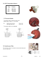
3.6 NTC-Temperature Sensor
Temp.
Resistor
10°C
25°C
60°C
90°C
9653 Ohm
4843 Ohm
1204 Ohm
445 Ohm
3.7 Pressure Switch
The pressure switch controls the water level.
Without water, contact 11 - 12 is closed.
fN
Switch point with level
Reset point with level
65 mm Ws
45 mm Ws
The pressure switch is not adjustable.
3.8 Interference Filter
The interference filter is connected in the terminal board parallel to the mains feed.
05.2002 R.K.
-6-
599 514
DE
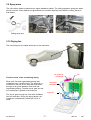
3.9 Spray arms
The new cutlery basket is placed at the upper diswasher basket. The celling sprayarm sprays the water
directly onto the cutlery basket and tguarantees an excellent washing result with the cutlery placed in
that basket.
Celling spray arm
upper spray arm
lower spray arm
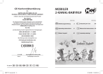
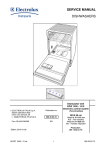
3.10 Drying fan
The new drying fan is located at the top on the rinse tank.
Function mode of the condensing drying
Rinse tank, fan and regenerating dosing with
condenser form a closed circuit. The humid air is
sucked from the top of the rinse tank and blown
through an air guide between rinse tank and
regenerating dosing. Thereby the air gets dry and
the condensate is guided to the drain tub.
The dry air gets through the rinse tank ventilation
into the rinse tank. During the drying phase, the
condenser is additionally cooled with 1 liter of
water.
05.2002 R.K.
fan
air guide for
condenser
-7-
rinse tank
ventilation
drain tub
599 514
DE
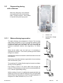
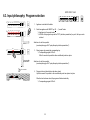
3.11
Regenerating dosing
with condenser
With every filling step, the condenser
cools down due to the cold incoming
water. Therefore another 1 liter of water
is required during the drying cycle.
3.11.1
Water softening/regeneration
The water softening can be adjusted in 10 levels. The incoming
water flows until positon 5 to 85 % through the softener which
works according to the ion exchange principle. The ion exchanger
is filled with small epoxy resin balls. The resins exchange the
hardness constituents (calcium and magnesium), for sodium
ions.
When all the sodium ions are used up, it is necessary to
regenerate the softener. This is done by flushing a brine solution
through the softener.
1.
softener unit
2.
regeneration dosage
chamber
2
1
Afterwards the softener is washed out with fresh water and is now
fully effective.
Depending on the water hardness, regeneration is only necessary
after several wash cycles.
The remaining 15 % of water flow through the rinse tank ventilation
directly into the appliance.
From setting of level 6, the whole water flows through the
softener. For this purpose you also have to set mechanically from
0 to 1 with the regenerating dosing.
With the setting of level 9, it is additionally regenerated after the
washing in a rinse cycle. With the settings 1 to 8, it is regenerated
after the final rinse depending on need. The softening system is
designed for a water hardness of up to 70 °dH.
05.2002 R.K.
-8-
2
1
599 514
DE
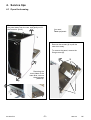
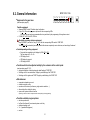
4. Service tips
4.1 Open the housing
To remove side panel remove fixing screws, pull
the panel away from the rear, and gently out of
the front trim. (pic.1).
You need
Torx epuipment
1
Remove the screws (1) to pull the
outer door away.
To remove the panel, remove the
fixing screws (2) .
2
Removing the
cover plates of the
base area, remove
these screwst
(Abb1+2).
2
05.2002 R.K.
1
3
-9-
599 514
DE
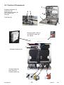
4.2 Position of Components
3
Detergent dispenser (1)
Spray arms (2)
Roof-mounted shower (3)
Salt container (4)
Filter (5)
4
5
2
1
Type plate (6)
6
Electronic EDW 1003 (1)
and ON/OFF-switch (2)
are clipsed
1
3
Detergent dispenser (3)
Thermal sensor (4)
Drain pump (5)
Pressure switch (6)
05.2002 R.K.
4
- 10 -
5
6
599 514
DE
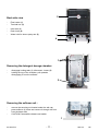
5
Back side view
-
Flow heater (1)
Terminal box (2)
-
Inlet hose (3)
Drain hose (4)
-
Water inlet for above spray arm (5)
1
4
2
3
1
Removing the detergent dosage chamber:
-
disengage locking tabs (1), disconnect hoses (2)
holding the top of the chamber, pull upwards
disengaging it from the softener.
2
Removing the softener unit :
-
remove the securing nut located under the salt cap.
press softener (1) down and remove it through the front
from the base area
CAUTION if accessible release reed switch.
1
05.2002 R.K.
- 11 -
599 514
DE
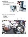
Removing the base :
-
remove side panels, rear panel and plinth panel
gently release base fixing clips with a screwdriver (figure)
take off base carefully and release circulation pump,
electronic and heater relay
disconnect the float switch
With
-
base removed, following components are accessible:
Drain pump (1)
Circulation pump (2)
Flow heater (3)
Temperature sensor / Turbidity sensor (4)
Pressure switch (5)
4
1
5
2
3
05.2002 R.K.
- 12 -
599 514
DE
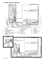
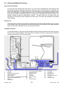
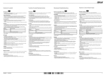
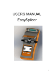
5. Water Course Scheme
2
22
3
21
7
4
15
23
24
21
1
12
6
5
11
8
9
18
16
10
19
14
1
2
3
4
5
6
7
8
9
20
17
Inlet valve
10
Air break
11
Regeneration water dosage
12
Overflow safety level
13
Safety overflow
14
Inlet to sump from regeneration dosage chamber
15
Regeneration dosage chamber
16
Softener
17
Salt container
Non-return valve salt container
Regeneration valve
Safety inlet hose
Base tray
Float switch
Pressure switch
Filter
Circulation pump
18
19
20
21
22
23
24
13
Flow heater
Drain pump
Non-return valve
Spray arms
Roof-mounted shower
Tub vent
Sump assembly
ohne
Sicherheitszulaufschlauch
Ausführung:
Kurze Regenerierdosierung
09.2002 R.K.
- 13 -
599 515 183
EN
5.1 All-Around Water Protection
Aqua-Control Inlet Hose
The inlet hose has a double-wall construction. The inner hose is equipped with a flow restrictor built
into the tap connection, and has a flow rate of 4 litres per minute. The inlet valve (1) is located in the
base of the dishwasher. The safety outer hose (12) is connected to the regeneration chamber. If the
inner hose should burst, the water passes into the tub. The safety pressure switch activates the drain
pump and decreases the waterlevel down to normal level. An additional overflow protection is a
defined overflow through the regeneration chamber. The water flows into the bottom tray and
activates the float switch, which energises the drain pump. This drains the dishwasher preventing
water damage.
Safety level
If the safety level is reached by over-fillling, the safety pressure switch starts the drain pump. The water
is only drained until it has reached the normal level because the reset point of the safety pressure
switch is above the switchpoint of the normal pressure switch.
Leakage Protection
The anti-flood switch in the base tray will activate the drain pump and drain the water from the tub in
the event of an internal leakage. If the float switch is activated, all electric components are switched
off except the electronic and the drain pump.
2
22
3
7
21
23
4
15
24
1
12
6
5
11
8
9
17
18
19
14
Inlet valve
10
Air break
11
Regeneration water dosage
12
Overflow safety level
13
Safety overflow
14
Inlet to sump from regeneration dosage chamber
15
Regeneration dosage chamber
16
Softener
17
Salt container
09.2002 R.K.
20
10
13
1
2
3
4
5
6
7
8
9
16
Non-return valve salt container
Regeneration valve
Safety inlet hose
Base tray
Float switch
Pressure switch
Filter
Circulation pump
- 14 -
18
19
20
21
22
23
24
Flow heater
Drain pump
Non-return valve
Spray arms
Roof-mounted shower
Tub vent
Sump assembly
599 515 183
EN
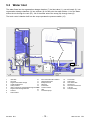
5.2
Water Inlet
The water flows into the regeneration dosage chamber (7) via inlet valve (1), over air break (2), into
regeneration dosage chambers (3) into softener (8). At this point the water divides. 1/4 of the water
enters the tub through the vent (23). 3/4 of the water enters the sump (24) through hose (6).
The level control chamber built into the sump operates the pressure switch (15).
2
22
3
7
21
23
4
15
24
1
12
6
5
11
8
9
Inlet valve
10
Air break
11
Regeneration water dosage
12
Overflow safety level
13
Safety overflow
14
Inlet to sump from regeneration dosage chamber
15
Regeneration dosage chamber
16
Softener
17
Salt container
09.2002 R.K.
17
20
18
10
19
14
13
1
2
3
4
5
6
7
8
9
16
Non-return valve salt container
Regeneration valve
Safety inlet hose
Base tray
Float switch
Pressure switch
Filter
Circulation pump
- 15 -
18
19
20
21
22
23
24
Flow heater
Drain pump
Non-return valve
Spray arms
Roof-mounted shower
Tub vent
Sump assembly
599 515 183
EN
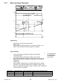
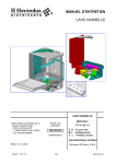
5.2.1
Water load steps (Example)
static water
load
dynamic water
load
to level
wit h level control
max. 4
repetitions
Timeout 1
Timeout 2
speed
in U /min
targetspeed
10 Sek.
5 Sek.
5 Sek.
≥20 Sek.
1600
time
in Sek.
0
water
in L
level c heck:
level c heck:
water failure displayed
if level not reac hed!
water failure displayed
if level not r eac hed!
3,6 - 4
dynamic
water load
ca. 1,6
static
water load
time
in Sek.
0
valve
filing
filling is possible
on
time
off
in Sek.
Static filling
-
Static filling until pressure switch point.
failure code:
If this point isnt reached after max. 2 minutes (Timeout 1), a
failure code is displayed and the program is stopped.
Dynamic filling
-
pulse wash
1
2
3
09.2002 R.K.
*)
10 seconds filling at reduced circulation pump speed
5 seconds pause
10 seconds filling at reduced circulation pump speed
filling with increasing circulation pump speed. As soon as the
target speed has been reached, it is filled up to the pressure
switchpoint.
Failure code:
If this dynamic switchpoint isn’t reached within total 4 minutes
(Timeout 2), the dynamic filling can be repeated 3 times. Only
after non-successful repeating 3 times, a failure code is displayed
and the program is stopped.
pulse 2800 1/min
0,9 sec
0,6 sec
0,3 sec
The target speed
is dependent on
the subsequent
pulse wash.
Pause 1600 1/min target speed in dynamic filling
4,5 sec
2200 1/min
3 sec
1900 1/min
1,5 sec
1700 1/min
- 16 -
599 515 183
EN
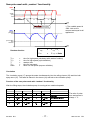
New pulse wash with random functionality
speed
in U /min
2800
var iable
s peed
1600
20 S ec.
s tar t-r outine
T high,r
T low
T high,r
T low
T high,r
time
in s ec.
0
-function
*) The variable speed is
1600 1/min at the
moment and equal to all
appliances.
T high,r = time (high s peed) + r andom time
water
in L
dynamic
pulse was h
level
pr ess ur e s witch
point
water level
time
in s ec.
0
Random-function
Thigh,r
Thigh
Tr
Tlow
Ratio
=
=
=
=
=
T
high, r
=
T
high
+ Tr
T
low
=
T
high, r
+ Ratio
time for high speed (calculated with random funktion)
time for high speed (cycle definition)
random time
time for low speed
factor for low speed (eeprom definition)
Circulation
The circulation pump (17) pumps the water simultaneously into the ceiling shower (22) and into both
spray arms (21). The water is filtered in the sieves (16) and led to the circulation pump.
Function of the new pulse wash with random functionality
After the filling steps, the circulation pump is running at two rotational speeds.
3XOVHWLPHPLQ
3XOVH :DVK
'H ILQLWLYH7LPH
VHF
5D QGRP7LPH
VHF
3DXVHPLQ
'HILQLWLYH 7LPH
5DQGRP7LPH
VHF
8VH Z LWK:DVK&\FOHV
SUHZDVKLQWHQVLYH
ZDVKLQWHQVLYH
VHF
VHF
VHF
ZDVKDQGLQWHUPHGLDWHZDVK
The ratio of pulse
time and pause is
always 1 : 5.
SUHZDVKQRUPDO
09.2002 R.K.
VHF
VHF
VHF
- 17 -
ULQVH
599 515 183
EN
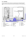
5.3 Draining
During the wash cycle the water is pumped out at various stages. First the draining water cleans the
filters (16). The filters are open at the bottom which allows any soilage to be rinsed off sufficiently.
There is a non-return valve (20) at the inlet connection to the drain pump (19). This valve prevents the
water
2
22
3
7
21
23
4
15
24
1
12
6
5
11
8
9
Inlet valve
10
Air break
11
Regeneration water dosage
12
Overflow safety level
13
Safety overflow
14
Inlet to sump from regeneration dosage chamber
15
Regeneration dosage chamber
16
Softener
17
Salt container
09.2002 R.K.
17
20
10
19
14
13
1
2
3
4
5
6
7
8
9
18
16
Non-return valve salt container
Regeneration valve
Safety inlet hose
Base tray
Float switch
Pressure switch
Filter
Circulation pump
- 18 -
18
19
20
21
22
23
24
Flow heater
Drain pump
Non-return valve
Spray arms
Roof-mounted shower
Tub vent
Sump assembly
599 515 183
EN
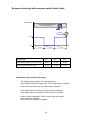
Sequence draining with pressure switch level check
drain pump
1 dr aining sequence
with variable timing
level c heck!
on
off
.
T1 (variable)
T2 (variable)
T3 (variable)
Drain Cycle
T1
T2
T3
First draining before every wash cycle
45 sec
15 sec
20 sec
Draining after the wash cycles
30 sec
20 sec
10 sec
New draining with sequence draining
-
The draining step contains of 3 time sequences.
In the middle sequence, during time T2 the drain pump is stopped.
-
At the end of the drain step, the water level is checked.
-
If the switch back is reached, the drain step is terminated.
If the switch back isn’t reached, the drain step is repeated.
-
A failure code is displayed, if after 2 drain steps, the switch
back couldn’t be reached.
In this case, the program is stopped.
19
6. Electronic EDW 1003
6.1 In- and output elements
09.2002 R.K.
- 20 -
599 515 183
EN
6.2. General information
l
EDW 1003 / VGA
Equipment in the panel area
(see description page B1)
LD1
LD2
LD3
LD4
LD5
LD6
S1
S2
S3
S4
S5
S6
LD7
LD8
LD9
LD10
LD11
LD12
Possible equipment:
w Separate ON/OFF switch S0 without optical confirmation.
w 6 keys S1 to S6 to select programs or options with the corresponding LEDs
All keys are free and can be programmed without any restriction by the programming of the appliance variant.
w 6 LEDs (LD7 to LD12) for SZV, PAA etc.
Absolutely necessary minimum equipment:
Keys S0 (ON/OFF) and the first 3 keys S1 to S3 with the corresponding LEDs and the "END" LED.
The keys S1 to S3 are absolutely necessary to select all customer respectively service functions, such as setting of hardness!
l
Variant-depending existing equipment:
w 3-step start-time preselection with display by LEDs LD7 to LD9
The time steps are 3h - 6h - 9h
w LED display for salt
w LED display for rinse-aid
w LED display for END
l
Functions which can be adjusted variably by the customer via the control panel:
(see description page B 11-13)
w display and alteration of water hardness by coded flashing of "END" LED
w Switching on/off of rinse-aid addition. Display by coded flashing of the "END" LED
w Switching on/off of signal sound "END". Display by coded flashing of the "END" LED
l
Miscellaneous:
w
w
w
w
w
regeneration depending on need
manufacturing test routine
several service functions (fault memory, single actuator selection, ...)
alternatively with or without fan drying
aqua control system in different versions
depending on electr. and mech. components and the corresponding variant programming
l
Possible selectable program options:
w
w
w
w
w
start-time preselection
half load "small quantity" as automatic system or with key
additional washing cycle
3 in 1 (special tablet program)
senitize
21
S0
EDW 1003 / VGA
6.3. Input philosophy: Program selection
1.
2.
LD1
LD2
LD3
LD4
LD5
LD6
S1
S2
S3
S4
S5
S6
LD1
LD2
LD3
LD4
LD5
LD6
LD7
LD8
LD9
LD10
LD11
LD12
S0
LD1
LD2
LD3
LD4
LD5
LD6
S1
S2
S3
S4
S5
S6
LD7
LD8
LD9
Appliance in switched-off condition
2.
Switch on appliance with ON/OFF key S0 -- "prestart" mode
Ä Appliance is in the prestart mode
Ä All LEDs of the program keys and the "SZV" (start-time preselection) key are lit, the keys can be
selected.
Selection of a start time possible
(see description page B 4 / "Input philosophy start-time preselection")
LD3
3.
S3
Select program by pressing the corresponding key.
Ä Corresponding program LED is lit.
Within 3 seconds it is possible to alter or additionally select an option.
Selection of a start time possible
(see description page B 4 / "Input philosophy start-time preselection")
Tür schließen
4.
4.
LD3
S0
1.
S0
3.
LD10
LD11
LD12
Program starts only when the door has been closed.
Up to this moment it is possible to alter or additionally select an option at any time.
When the door has been closed, the program will start automatically.
Ä Corresponding program LED is lit.
22
6.4. Input philosophy: select start time
Variant A
Variante B
time preselection after program selection
time preselection before program selection
1.
2.
LD1
LD2
LD3
LD4
LD5
LD6
S1
S2
S3
S4
S5
S6
LD1
LD2
LD3
LD4
LD5
LD6
LD7
LD8
LD9
LD10
LD11
LD12
S0
S0
3.
LD3
S3
4.
LD3
LD6
3h
6h
12h
S6 =SZV
3h
6h
9h
3h
6h
9h
3h
6h
9h
3h
6h
9h
5.
LD3
LD6
3h
6h
9h
S6 =SZV
3 Sekunden
Pr o
Tastendruck
+ 1 Stufe
ç Variant A
1. Appliance in switched-off condition
2. Switch on appliance by ON/OFF key S0
Ä Appliance in "prestart" mode
Ä All LEDs of program and option keys are lit,
the keys can be selected.
3. Select program by pressing the corresponding key.
Ä Corresponding program LED is lit.
4./5. Actuate start-time preselection key within 3 seconds
Ä Key LEDs of program and "SZV" are lit
Ä The "SZV" is indicated by the first lighting time LED.
Any additional key pressure causes the start time scrolling by
1 step 3h - 6h - 9h - "SZV" LEDs off (SZV=0h) - 3h - 6h - ...
6. 3 seconds after the last actuation of the "SZV" key the adjusted
start time gets active and runs down after the door has been closed.
Ä The key LEDs of program and "SZV" are lit
Ä The adjusted "SZV" is indicated by the lighting time LED.
1.
2.
LD3
3h
6h
9h
LD3
LD4
LD5
LD6
S1
S2
S3
S4
S5
S6
LD1
LD2
LD3
LD4
LD5
LD6
Variant B è
1./2. like variant A
3. Actuate start-time preselection key.
Ä LED of "SZV" key is lit.
Ä The "SZV" is indicated by the first lighting time LED.
Any additional key pressure causes the start time scrolling by
1 step 3h - 6h - 9h - "SZV" LEDs off (SZV=0h) - 3h - 6h - ...
5.
Star t zeitvorwahl läuft ab
6.
As long as no washing cycle is selected, the display remains as
is. The selected start time is not active!
Select program by pressing the corresponding key.
Ä Program LED and time LED are lit.
Ä The LED of the start-time preselection key goes out
3 seconds after the last actuation of a key the adjusted start
time gets active and runs down after the door has been closed.
Ä The key LEDs of program and "SZV" are lit
Ä The set "SZV" is displayed by the lighting time LED.
23
LD7
LD8
LD9
LD10
LD11
LD12
S0
LD6
3.
3h
6h
9h
S6 =SZV
3h
6h
9h
3h
6h
9h
3h
6h
9h
3h
6h
9h
LD6
4.
4.
LD6
LD2
S0
3h
6h
9h
S6 =SZV
Star t zeit wird er st aktiv wenn
Programm gewählt wird
5.
LD3
3h
6h
9h
S3
(With the setting 0h all LEDs of program and option keys are lit)
6.
LD1
3 Sekunden
6.
LD3
LD6
3h
6h
9h
Star t zeitvorwahl läuft ab
Pr o
Tastendruck
+ 1 Stufe
6.5. Input philosophy: program sequence
A special feature with the fully integrated appliances is the condition that there are no control and display elements visible when the door has been closed.
That is why important information for the customer, such as the cycle end or information on faults is indicated acoustically in addition..
This result in a few differences for the start, run and end of a cycle in comparison with normal upright, substructure resp. integrated variants of appliances.
l
Cycle start
w
w
l
The cycle starts finally only when the door has been closed!
After the door has been closed and the cycle has started successfully it is no more possible to make any alterations etc.
But to make changes in the program setting in exceptional cases, you have to open the door during the running cycle.
F interrupt resp.delete cycle
(see description page B 6 / Delete cycle")
F change resp. alter cycle
(see description page B 7.2 / "Reselect cycle")
Cycle run
As already described above there are no displays visible with VGA appliances caused
by the type of construction. The optical displays are selected but hidden by the worktop.
w
w
l
The LEDs of the selected washing cycle are lit during the whole cycle run.
There are no displays which indicate the cycle state.
Cycle end
As already described above there are no displays visible with VGA appliances caused
by the type of construction. The optical displays are selected but hidden by the worktop.
w
w
w
w
When the cycle has ended, an acoustic signal will sound.
The acoustic "end" signal is a whistling sound with the following interval:
15 seconds on - 3 minutes off - 15 seconds on - 3 minutes off - 15 seconds on - completely off
The "end" signal is cleared immediately by opening the door.
The confirmation LED of the program key of the run-down cycle and the "END" LED are lit,
but are cleared immediately by opening the door.
When the cycle end has been reached, it is possible to delete the run-down cycle by
opening and closing the door. After closing the door, the appliance is automatically
again in the "prestart" mode, i.e. a new program could be selected again at once.
In order to switch off the appliance completely you have to actuate the ON/OFF key S0.
Even in this case, the run-down cycle is deleted. All displays go out.
24
EDW 1003 / VGA
6.6. Input philosophy: delete program
A selected or already started washing cycle can be delted at any time during normal operation
l
Delete program (using the reset function)
LD1
LD2
LD3
LD4
LD5
LD6
S1
S2
S3
S4
S5
S6
LD7
LD8
LD9
LD10
LD11
LD12
Remaining function always with key S2 and S3
LD5
1.
1.
Cycle is running
2.
Actuate reset keys S2 and S3 for about 2 seconds
Ä LED of the running cycle starts flashing
3.
After about 2 seconds all LEDs of program and option
keys are lit. The program is deleted.
The appliance is in the "prestart" mode.
blinkt
LD5
2.
S2
S3
2 Sekunden
3.
LD1
LD2
LD3
LD4
LD5
LD6
25
S0
EDW 1003 / VGA
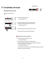
6.7.1. Input philosophy: alter program
l
Alter program during the prestart phase
LD1
LD2
LD3
LD4
LD5
LD6
S1
S2
S3
S4
S5
S6
LD7
LD8
LD9
LD10
LD11
LD12
S0
The door is still open at that moment!
LD3
1.
1.
Program has been selected but did not yet start.
Ä Corresponding program LED is lit.
2.
By pressing the new desired program key shortly it is possible to alter directly.
Options already selected before are cleared and have to be selected anew.
Ä New selected program LED is lit.
3.
Before the door has been closed it can be altered as many times as one wants.
LD5
2.
S5
3.
LD2
S2
Only when the door has been closed, the program will start automatically.
Special feature when a start time was selected before!
1.
Program and start time have been selected but did not yet start.
Ä Cycle LED and "SZV" LED are lit.
2.
By pressing the new desired program key shortly it is possible to alter directly.
The already selected start-time preselection keeps to be after the alteration! Cycle options selected
before however are deleted and have to be selected anew.
Ä New cycle LED and "SZV" LED are lit.
If the selected start time is already running down (the time in the display is lit permanently) you have to press the
new desired cycle key a longer time (about 6 seconds).
26
EDW 1003 / VGA
6.7.2. Input philosophy: alter program
l
Alter program after successful cycle start
1.
LD1
LD2
LD3
LD4
LD5
LD6
S1
S2
S3
S4
S5
S6
LD7
LD8
LD9
LD10
LD11
LD12
LD3
1.
Open the door for altering the program!
2.
Opening the door stops the cycle.
Ä Corresponding cycle LED is lit.
3.
Press key of the new desired program (in our example S5) for aprox. 6 seconds.
Ä Display LED of the running cycle starts flashing.
4.
After this time the previous cycle LED goes out and the cycle LED
of the new desired program is lit.
5.
The program will start automatically when the door has been closed.
Tür öffnen
2.
LD3
blinkt
3.
LD3
S5
3 Sekunden
4.
LD5
Tür schließen
5.
LD3
If a program is altered after an already started cycle the new cycle starts
generally from the beginning! This is also indicated in the display by the running time.
Options already selected before are deleted and have to be selected anew.
27
S0
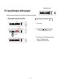
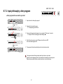
6.8. Input philosophy - interrupt program
l
Interrupt program
w
w
w
w
w
l
Using the ON/OFF key S0 it is possible to interrupt the program as long as one wants.
The same is valid for an interruption by opening the door.
There is no deleting function integrated in the ON/OFF key S0!
If the cycle is interrupted using the ON/OFF key, all displays go out.
The cycle run is continued after switching on again using the ON/OFF key S0 resp.
by closing the door, without that another key actuation becomes necessary.
Information: The cycle is continued with a short time delay.
All displays and confirmations appear in the same condition as before the interruption.
What happens when opening and closing the door?
w
w
Appliance is switched on and in the "prestart" mode
w After opening the door all indications keep to be displayed on the panel. The power
supply of the electronic is fully guaranteed as long as the appliance remains switched on.
The door is open during the running cycle
w After opening the door all indications keep to be displayed on the panel as long
as the appliancekeeps to be switched on using the ON/OFF switch S0.
w When the door has been closed, the appliance will start automatically and the cycle run will be continued.
Attention:
w
l
When the 1. regeneration has been reached in the program part "drying" it is valid:
w When the door is open longer than 30 seconds, the program is cleared.
When the door has been closed, the appliance is automatically again in the "prestart" mode.
A new program could be selected again immediately.
w Switching off the appliance by pressing the ON/OFF key S0 also deletes the current program from that moment.
(see description page B 3 / "Input philosophy: program selectionl")
What happens in case of resp. after a power failure?
w
w
w
In case of a power failure the appliance behaves as when it would be switched off using the ON/OFF key.
(see description above / under "interrupt program")
After the mains have returned the appliance behaves as after being switched on using the ON/OFF key S0.
The cycle continues after a power failure without necessary key actuations.
28
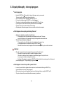
6.9. Input philosophy - displays
All displays are designed as LED displays and exist depending on variant.
A special feature with the fully integrated appliances is that there are no control and display elements visible when the door has been closed.
l
Displays for program selection and option
Ä Above resp. next to a program or option key there is generally a corresponding LED to confirm the selected function.
Ä They is lit pernanently during the whole cycle run.
l
Display for start-time preselection (SZV)
Ä The start-time preselection is indicated by 3 LED displays.
Ä The start time is counted down to 0h in the steps predetermined by the LED graduation.
Ä The start-time setting is displayed scrolling.
3h - 6h - 9h - 0h ("SZV" LED off) - 3h - 6h - 9h - ....
Ä When the start time has run down all "SZV" LEDs are off.
l
Run time display (RLA)
Ä With EDW1300 appliances this does generally not exist
l
Information displays
Ä The LED position is depending on the programming of the variant.
They can be programmed to any LED which is not programmed with a program or option key.
Ä Th
Ä The information LEDs go out during the whole cycle run!
w LED display "salt"
Ä LED is lit in case of a lack of salt
Ä LED goes out when salt has been refilled
(Depending on the salt dissolution it can take some time until the LED goes out).
Information: LED display "salt" goes out with hardness setting 1
(no regeneration necessary)
w LED display rinse-aid
Ä LED is lit in case of a lack of rinse-aid
Ä LED goes out after rinse-aid has been refilled
Information: The rinse-aid display can be deactivated completely by the customer, depending on
variant. This also deactivates the LED display "rinse-aid".
(see description page B 12 / "Deactivation of rinse-aid addition")
If the option "3 in 1" is selected (special tablet option), neither the "salt" nor the "rinse-aid" LED is selected.
w LED display "water"
Ä LED is lit, when there is no or too less water filling into the appliance.
A reason for that could be, for example, a closed water tap.
Ä The program is stopped and can be continued when the fault has been eliminated by actuating the program key.
(see also description page B 19 / "Survey of fault displays - fault 10")
29
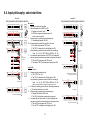
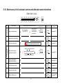
6.10. Short survey of all customer, service and aftersales service functions
EDW 1003 / VGA
manufacturing /
service
Customer
Who?
Which function?
LD1
LD2
LD3
LD4
LD5
LD6
S1
S2
S3
S4
S5
S6
LD7
LD8
LD9
Selection of special mode customer or service
setting of water hardness
à
deactivation rinse-aid addition
à
deactivation signal sound
à
switch on appliance
with ON/OFF S0
press S2 and S3
simultaneously
and keep them
pressed until ...
à
LD10
LD11
LD12
S0
Confirmation
of the special mode
... LEDs of
keys S1 - S3
are flashing
Bei Aufruf der Kunden-Funktionen darf
generell kein Spülprogramm gewählt sein!
press S1 and S3 simultaneously
and
switch on appliance with ON/OFF S0.
Keey keys S1 and S3 pressed for
another aprox. 4 seconds until ...
... LEDs of
keys S1 - S3
are flashing
Call
of special function
Detailled
description
à
press
key S1
see page B 11
à
press
key S2
see page B 12
à
press
key S3
see page B 13
à
press
key S1
see page B 14
readout of fault memory
single actuator selection
à
LED test with integrated
deletion of fault memory
à
à
press
key S2
see page B 15
manufacturing test routine
à
à
press
key S3
see page B 16
deactivation Pulse Wash
à
à
press
keys S2 + S3
see page B 17
additional washing cycle
à
à
press
keys S1 + S2
see page B 18
30
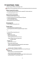
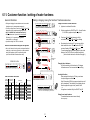
6.11. Customer function / setting of water hardness
General information
Calling / changing / saving the "electronic" hardness area value
w Setting and changing the water hardness area is executed in
all designs resp. key arrangements analogously.
w For that you always have to use the keys S0, S1, S2 and S3
independent of their variant-depending program load.
w Key S1 is ALWAYS the "water hardness area key"
w Water hardness area 4 is preset by the manufacturer.
With setting "1L" it is generally not regenerated.
A salt addition is not necessary.
w A possible existing "salt" LED is not selected.
1.
2.
LD1
LD2
LD3
LD4
LD5
LD6
S1
S2
S3
S4
S5
S6
LD1
LD2
LD3
LD4
LD5
LD6
LD1
LD2
3.
LD1
LD2
codiertes blinken!
ENDE
S1
blinkt
LD1
codiertes blinken!
ENDE
blinkt
LD1
LD2
LD3
LD4
LD5
LD6
Table for hardness area values:
S0
Anzahl blinken
akustisch
elektronisch mechanisch
1 mal
2 mal
3 mal
4 mal
5 mal
6 mal
7 mal
a
8 mal
9 mal
10 mal
1
2
3
4
5
6
7
8
9
10
0
1
Wasserhärte
in dH
Bemerkung
in mmol/L
bis
4
4
bis
10
11
bis
15
bis
19
bis
23
29
... AUS nach 60sek. automatisc h
Bereich
bis
0,7
I
0,7
bis
1,8
I / II
14
1,9
bis
2,5
18
2,6
bis
3,2
22
3,3
bis
3,9
bis
28
4,0
bis
5,0
bis
36
5,1
bis
6,4
37
bis
42
6,5
bis
7,5
43
bis
50
7,6
bis
8,9
51
bis
70
9,0
bis
12,5
kein Regenerieren
II
S0
III
3.
Press keys S2 and S3 simultaneously until the
confirmation LEDs LD1, LD2 and LD3 are flashing
4.
By actuating the function key S1 you now can call the
water hardness function. The confirmation LED LD1
continues flashing, LEDs LD2 and LD3 go out.
The set hardness area is indicated optically by the coded
flashing of the "END" LED and in addition acoustically.
( see for that the table on the left side of this page! )
Changing the set hardness
Any further actuation of the function key S1 changes
the hardness area. This increases the value scrolling.
codiertes blinken!
ENDE
Einstellung der
Härtestufe
Switch on appliance by ON/OFF key S0 -- "prestart" mode
Ä All LEDs of program and option keys are lit.
Pr o
Tastendr u c k
+ 1 Stufe
S0
Anzeige
Ende-LED
2.
S1
LD1
S3
Calling the function "set water hardness"
1. Appliance in switched-off condition
S3
blinkt
LD1
4.
LD3
S2
S0
LD3
S2
ENDE
S1
he
S0
Verschneideschalter
EDW 1003 / VGA
LD10
LD11
LD12
blinken
Electronic and mechanical setting with the appliance:
w Next to the "electronic" setting on the control panel described
at the right you also have to pay attention to the mechanical
setting in the appliance by the 2-step blending switch.
(see for that the table for hardness area values)
LD7
LD8
LD9
... AUS durch manuelle Betätigung über Ein/Aus
Leaving the function
After pressing the function key S1 last you can leave
the special program as follows.
After 60 seconds all LEDs of program and option keys will
be lit automatically. The indication in the display goes out.
Now the appliance is again in the "prestart" mode
or
the appliance is switched off by the ON/OFF key S0.
Saving the set water hardness
The selected hardness area is saved directly
IV
after every entry.
doppelt Regenerieren
31
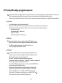
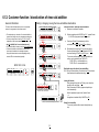
6.12. Customer function / deactivation of rinse-aid addition
General information
Calling / changing / saving the rinse-aid addition deactivation
The function rinse-aid deactivation does not exist generally
and must be programmed in the software variant.
1.
w The deactivation resp. activation of the rinse-aid addition is
executed in all designs resp. key arrangements analogously.
w For that you always have to use keys S0, S1, S2 and S3
independent of their variant-depending program load.
w Key S2 is ALWAYS the "rinse-aid disactivation key"
w The rinse-aid addition is always set active by the manufacturer.
w If the rinse-aid addition is deactivated, it means that no
more rinse-aid is added via the detergent dispenser.
Along with the deactivation a variant-depending existing
rinse-aid LED is also deactivated generally:
2.
LD1
LD2
LD3
LD4
LD5
LD6
S1
S2
S3
S4
S5
S6
LD1
LD2
LD3
LD4
LD5
LD6
LD7
LD8
LD9
Calling the function "deactivate rinse-aid addition"
1. Appliance in switched-off condition
LD10
LD11
LD12
S0
3.
LD1
LD2
LD3
S2
LD2
LD2
4.
blinkt
ENDE
LD2
5.
blinkt
4.
By actuating the function key S2 you now can call the
function rinse-aid addition. The confirmation LED LD2
continues flashing, LEDs LD1 and LD3 go out.
The current condition whether the rinse-aid addition is
active or not is signalled by the "END" LED.
"END" LED on = rinse-aid addition on
"END" LED off = rinse-aid addition off
Deactivation resp. activation of rinse-aid addition
5. / 6. By any further actuation of the function key S2 you activate
resp. deactivate the addition alternating.
LD3
S3
Press keys S2 and S3 simultaneously until the
confirmation LEDs LD1, LD2 and LD3 are flashing
ENDE
ENDE
S2
3.
S3
S2
LD1
Switch on appliance with ON/OFF key S0 -- "prestart" mode
Ä All LEDs of program and option keys are lit.
S0
blinken
S2
EDW 1003 / VGA
2.
S0
LD2
6.
blinkt
ENDE
S2
LD1
LD2
LD3
LD4
LD5
Leaving the function
After pressing the function key S1 last you can leave the
special function as follows.
After 60 seconds all LEDs of program and option keys
are lit automatically.
Now the appliance is again in the "prestart" mode
or
the appliance is switched off by ON/OFF key S0.
LD6
S0
... AUS nach 60sek. automatisch
S0
... AUS dur c h manuelle Betätigung über Ein/Aus
Saving the set condition
The currently valid condition is saved directly after any
entry.
32
When calling the customer function a washing cycle
must not be selected generally!
6.13. Customer function / deactivation of signal sound
General information
Calling / changing / saving the signal sound deactivation
The function deactivation of the signal sound at the cycle end
does not exist generally and must be programmed in the
software variant.
1.
w The deactivation resp. activation of the signal sound is
executed in all designs resp. key arrangements analogously.
w For that you always have to use keys S0, S1, S2 and S3
independent of their variant-depending program load.
w Key S3 is ALWAYS the "signal sound deactivation key"
w The signal sound is always set active by the manufacturer.
w If the signal sound is deactivated, it means that in
general no acoustic end signal will sound any more.
Even the acoustic fault signals cannot be heard any more!
2.
LD1
LD2
LD3
LD4
LD5
LD6
S1
S2
S3
S4
S5
S6
LD1
LD2
LD3
LD4
LD5
LD6
LD7
LD8
LD9
Calling the function "signal sound deactivation"
1. Appliance in switched-off condition
LD10
LD11
LD12
S0
3.
LD1
LD2
LD3
S2
LD2
LD3
4.
blinkt
ENDE
LD3
5.
blinkt
4.
By actuating the function key S3 you now can call the
function. The confirmation LED LD3 continues
flashing, LEDs LD1 and LD2 go out.
The current condition whether the signal sound is
active or not is signalled by the "END" LED.
"END" LED on = signal sound on
"END" LED off = signal sound off
Deactivation resp. activation of the signal sound
5. / 6. By any further actuation of the function key S3 you
activate resp. deactivate the signal sound alternating.
LD3
S3
Press keys S2 and S3 simultaneously until the
confirmation LEDs LD1, LD2 and LD3 are flashing.
ENDE
ENDE
S2
3.
S3
S3
LD1
Switch on appliance with ON/OFF key S0 -- "prestart" mode
Ä All LEDs of program and option keys are lit.
S0
blinken
S3
EDW 1003 / VGA
2.
S0
LD3
6.
blinkt
ENDE
S3
LD1
LD2
LD3
LD4
LD5
Leaving the function
After pressing the function key S1 last you can leave the
special program as follows.
After 60 seconds all LEDs of program and option keys
are lit automatically.
Now the appliance is again in the "prestart" mode
or
the appliance is switched off by ON/OFF key S0.
LD6
S0
... AUS nach 60sek. automatisch
S0
... AUS durch manuelle Betätigung über Ein/Aus
Saving the set condition
The currently valid condition is saved directly after
any entry.
33
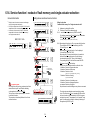
6.14. Service function / readout of fault memory and single actuator selection:
General information
Calling above-mentioned service function
w Calling the service functions is executed in all designs
resp. key arrangements analogously.
w For that you always have to use keys S0, S1, S2 and S3
independent of their variant-depending program load.
w In the service function mode, the key S1 is ALWAYS
responsible for the function "readout of fault memory"
and "single actuator selection".
1.
LD2
LD3
LD4
LD5
LD6
S1
S2
S3
S4
S5
S6
Calling the functions
"readout of fault memory" and "single actuator selection"
LD10
LD11
LD12
S0
S3
S0
1. Appliance in switched-off condition
2. Press keys S1 and S3 simultaneously and
3. / 4. ... and switch on the appliance by ON/OFF switch S0.
For that keep pressed keys S1 and S3 until the 3 confirmation
LEDs LD1, LD2 and LD3 are flashing.
S1
S3
S0
3.
(A temporary flashing up of LEDs is possible and is no fault!)
LD3
S3
LD7
LD8
LD9
S1
5. / 6. By actuating the function key S1 you now can call the function.
The confirmation LED LD1 continues flashing, the LEDs
LD2 and LD3 go out.
By pressing key S1 the first time the 1. fault is displayed
in a coded way via the "END" LED.
By pressing key S1 a second and third time it is possible to
read out the second and third value of the fault memory.
(see description page B 19 / "Survey of fault displays")
From pressing the key S1 the fourth time onward the LED
LD1 goes out and LD2 starts flashing.
Now you can call the single actuators one after the other.
4. Actuation: Selection of regeneration valve
5. Actuation: Selection of drain pump
6. Actuation: Selection of valve
3-4 Sekunden
ENDE
S1
LD2
2.
EDW 1003 / VGA
LD1
LD1
S0
LD1
4.
LD2
LD3
S1
S3
LD1
5.
alle blinken
S0
LED blinkt
S1
LD1
LED blinkt
Anzeige 2. + 3.Fehlers
S1
pro Tastendruck
1 Weiterschaltung
LED blinkt
LD2
Anzeige
der Einzelaktoren
S1
(filling to level - if level already existing, no filling)
S1
LD1
6.
7. Actuation: Selection of heating
(only when level detected)
LED blinkt
8. Actuation: Selection of circulation pump
9. Actuation: Selection of detergent dispenser
10.Actuation: Selection of drying fan
All positions can be called scrolling as many times as one wants.
S1
It is generally valid:
For calling all service functions you always have first to
actuate function keys S1 and S3 before switching
on the appliance by ON/OFF switch S0!
The keys have to remain pressed aprox. 4 seconds
to activate the function.
This procedure is intentionally different to that for the
customer functions.
LD1
LD2
LD3
LD4
LD5
LD6
S0
... AUS nach 60sek. automatisch
S0
. . . A U S d u r c h m a n u e l l e B e t ä t i g u n g ü b e r E i n /A u s
34
The single steps are switched onward manually by pressing
a key. If the function key S1 is not pressed within 60 seconds,
the service function is left automatically. All LEDs of program
and option keys are lit. The appliance is in the "prestart" mode
again. It is also possible to leave the function by switching off
the appliance by ON/OFF key S0.
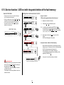
6.15. Service function / LED test with integrated deletion of the fault memory:
General information
Calling above-mentioned service function
w Calling the service functions is executed in all designs
resp. key arrangements analogously.
w For that you always have to use keys S0, S1, S2 and S3
independent of their variant-depending program load.
w In the service function mode the key S2 is ALWAYS
responsible for the function "LED test with integrated
deletion of the fault memory".
1.
LD1
LD2
LD3
LD4
LD5
LD6
S1
S2
S3
S4
S5
S6
LD7
LD8
LD9
Calling the functions
"LED test with integrated deletion of the fault memory"
LD10
LD11
LD12
S0
S1
S3
S0
EDW 1003 / VGA
LD2
LD3
S1
S2
S3
Appliance in switched-off condition
2.
Press keys S1 and S3 simultaneously and ...
3. / 4. ... and switch on the appliance by ON/OFF switch S0.
For that keep the keys S1 and S3 pressed simultaneously
until the 3 acceptance LEDs LD1, LD2 and LD3 are flashing.
3.
LD1
1.
2.
S1
S0
S3
(A temporary flashing up of LEDs is possible and is no fault! )
3-4 Sekunden
ENDE
S0
4.
LD1
LD2
LD3
S1
alle blinken
5.
S3
S0
By actuating the function key S2 you now can call the
function.
All LEDs are flashing aprox. 30 seconds.
Display und alle LED blinken
5.
Leaving the function / deletion of the fault memory
S2
LD1
LD2
LD3
LD4
LD5
After all above-mentioned LEDs resp. the display have been
flashing for aprox. 30 seconds the function is left automatically.
All LEDs of the program and option keys are lit.
Now the appliance is in the "prestart" mode again.
It is also possible to leave the function by switching off the
appliance by ON/OFF key S0.
LD6
S0
... AUS nach30sek. automatisch
In any case, the service fault memory is deleted.
S0
It is generally valid:
For calling all function keys you always have to actuate
first the function keys S1 and S3 before switching on
the appliance by ON/OFF switch S0!
The keys have to remain pressed aprox. 4 seconds
to activate the functionl.
This procedure is intentionally different to that for the
customer functions.
... AUS durch manuelle Betätigung über Ein/Aus
35
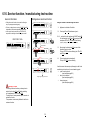
6.16. Service function / manufacturing test routine:
General information
Calling above-mentioned function
w Calling the service functions is executed in all designs
resp. key arrangements analogously.
w For that you always have to use keys S0, S1, S2 and S3
independent of their variant-depending program load.
w In the service function mode the key S3 is ALWAYS
responsible for calling the "manufacturing test routine".
1.
LD2
LD2
LD3
LD4
LD5
LD6
S1
S2
S3
S4
S5
S6
S1
S0
1.
Appliance in switched-off condition
2.
Press keys S1 and S3 simultaneously and ...
S0
3. / 4. ... and switch on the appliance by ON/OFF switch S0.
For that keep the keys S1 and S3 pressed until the 3
acceptance LEDs LD1, LD2 and LD3 are flashing.
3.
S1
LD3
S3
Calling the function "manufacturing test routine"
LD10
LD11
LD12
S3
S0
S3
(A temporary flashing up of LEDs is possible and is no fault! )
3-4 Sekunden
ENDE
S1
LD7
LD8
LD9
2.
EDW 1003 / VGA
LD1
LD1
S0
4.
LD1
S1
5.
LD2
LD3
alle blinken
S3
LD3
By actuating the function key S3 you can call the
manufacturing test routine.
The key LED LD3 continues flashing, the LEDs LD1
and LD2 go out.
6.
The test routine starts automatically.
The key LED LD3 continues flashing.
S0
blinkt
S0
S3
6.
5.
LD3
S0
Fertigungsprüfprogramm läuft
Generally it is valid:
For calling all service functions you always have to
actuate function keys S1 and S3 before switching
on the appliance by ON/OFF switch S0!
The keys have to remain pressed aprox. 4 seconds to
activate the function.
This procedure is intentionally different to that for the
customer functions.
36
From that moment the same input philosophy is valid for the
manufacturing test routine as for normal washing cycles
F cycle run and cycle end
(see description page B 5)
F clear cycle in advance
(see description page B 6)
F interrupt program
(see description page B 8)
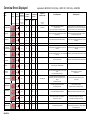
Overview Errors Displayed
Error
Name
Display
on
Screen
EDW 1500
Display
by
END LED
Acoustic
Indication
2Hz / 5sec. Pause
2Hz / 5sec. Pause
EDW1100
If available for
this model
No.of Beeps
Applicable for EDW1500 / 1503 (VGA) -- EDW1100 / 1003 (VGA) -- EDW2000
Error Display
visible for
Customer**
Display
PAA
AK
Call
Error Memory
(Service)
Display
PAA
Output via
Indicator Lamp
Short Explanation
What happens?
AK
If available for
this model
Water tap closed
1x
flashing
1x
J
J
J
J
LED Water
Switchpoint of pressostat is not reached
after max. 60 secs.
(only in programme steps incl. Filling up to level!)
Programme stops and can be continued after error remedy by
pressing the programme key. If fault is not corrected and programme
key is pressed, the machine runs dry until next subprogramme.
Drain pump
2x
flashing
2x
J
J
J
J
---
Reset point of pressostat is not reached after max. 120secs.
Programme stop.
Programme stops and can be continued after error remedy
by pressing the programme key.
Aqua-Control
3x
flashing
3x
J
J
J
J
---
Aqua-Control System switches off solenoid directly.
Programme stops and restarts automatically when error has
terminated.
Recycling pump
Triac short-circuit
5x
flashing
5x
J
J
J
---
Tacho signals are recognized although rec. pump is not
selected.
Programme stops and water is filled up until reset point of
pressostat
Heating
6x
flashing
6x
J
J
---
NTC Sensor
7x
flashing
7x
J
J
---
NTC short-circuit or break.
EEPROM
8x
flashing
8x
---
Communication error with ext. EEPROM
Check sum
MCF / CCF
9x
flashing
9x
Sprayarm blocked
10 x
flashing
10 x
Turpidity sensor
11 x
flashing
Communication
error
J?
During heating, temperature rise by min. 1.5K is not detected
Programme is continued until its end without heating function!
within 3min.
Programme is continued until its end without heating function!
J
J
---
Check sum (model programming) MCF or Check sum CCF
not OK.
Only recognized after switching on!
Programme selection not possible.
On/Off LED is on
J
J
LED Spray arm
At programme start and each subprogramme start,
also after door open/close or mains failure, spray arm
rotation
is checked and evaluated.
Error display until sprayarm speed is recognized,
or if no control.
11 x
J
J
---
The turbidity signal required for calibration
is not reached with 15secs.
Always recognition of turbidity.
Programme sequence is adapted accordingly.
12 x
flashing
12 x
J
J
---
Communication failure with User Interface.
Machine stops, waiting until communication is cleared.
Tacho
13 x
flashing
13 x
J
J
---
Recycling pump selected, but no tacho signal
recognized for 5 + 20 secs
Recycling pump without control, heating off.
This function is checked again on each step.
Filling time error
15 x
flashing
15 x
J
J
---
Time limit during filling exceeded
Programme is completed until next subprogramme without
level. No further filling up of water top up. Error is reset after
one complete drain cycle.
J
**
DGN-TDS-N
= If 7-Segment display available, no PAA error display/Sound error display generally with VGA, with other machines depending on model
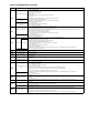
List of Possible Error Causes
Possible error causes
Code
i10
Water tap is closed or faulty
No water pressure, pressure too low or changing
Screen in front of inlet valve clogged
Flow governor at inlet valve faulty
No or not enough water let in
Inlet valve faulty
Inlet valve deenergized (faulty wiring or no activation by electronics)
Inlet hose bent
Softener system clogged (by filling detergent into salt compartment, for instance)
Upright installation without upright assembly kit
Machine runs dry (Siphon
Connection height of the discharge hose is lower than 30cm above appliance base
effect)
Connection w/o siphon or air chamber
Pressure controller faulty
Water level inside appliance is Pressure controller hose obstructed, bent or leaking
not detected
Pressure controller wiring is faulty
Screens in the appliance clogged (also check spray arm nozzles for clogging)
Fault with discharge pump
Discharge pump deenergized (faulty wiring or no activation by electronics)
Water is not pumped off
i20
i30
Discharge hose bent or connection height above 100cm
Ball valve in discharge trough glued / blocked (discharge pump does not aerate)
Pressure controller faulty
Water level inside appliance is
Pressure controller hose obstructed or bent
not detected
Insulation fault with heating element
Leakage
Leakage at recipient, discharge trough, hose system (e.g., Y-type hose), regeneration dosage etc.
Inlet valve faulty (does not close)
Water inlet too high (faulty flow governor at inlet valve)
Connecting hose regenerating dosing to discharge trough blocked
Water remains
Water inlet channels in regeneration dosing unit blocked
in base trough
Overflow
Screens in the appliance clogged (also check spray arm nozzles for clogging)
Pressure controller faulty
Pressure controller hose obstructed, bent or leaking
Pressure controller wiring is faulty
Foam production in the appliance (splashed rinsing liquid / leaking dosing unit or con-compatible detergent / rinsing agent used)
Base trough is dry
Inlet valve or wiring electrically interrupted
i50
Motor triac short-circuit
i60
No rise in temperature
i70
NTC signal faulty
i80
Check sum error EEPROM
i90
Check sum error model
programmation
Upper spray arm does not
rotate
iA0
No spray arm detection
ib0
ic0
turbidity signal faulty
communication faulty
Circulation pump no function
id0
iF0
Obstruction/blocking (filters in the appliance, discharge opening in discharge trough, discharge pump, discharge hose, siphon, cover plug at
siphon connection not removed during first commissioning)
No tacho signal
recognized
Time limit during filling
exceeded
Faulty electronics
Heating element faulty
Heating element deenergized (faulty wiring or no activation by electronics)
Thermal sensor defect
Wiring faulty (e.g. short-circuit or interruption)
Mains filter defect
Faulty electronics
EMC problem
Faulty electronics
Blocking by dishes or cutlery basket
Nozzles clogged (drive nozzles at spray arm extremities)
Spray arm leaking (welding seam)
Spray arm bearing blocked (dirt, foreign bodies)
Screens in the appliance clogged
Bellows at connecting pipe not sealed at recipient rear wall (bellows not contacting/glued together)
Circulating pump does not reach full power (nominal speed is not reached due to winding influence)
Too little water in appliance - for possible causes see Error codes i10 and iF0
Foam production in the appliance (splashed rinsing liquid / leaking dosing unit or con-compatible detergent / rinsing agent used)
No magnet in spray arm
Spray arm detection sensor faulty
Wiring faulty
turbidity sensor defect
Wiring faulty
turbidity sensor dirty
Foam production in the appliance (splashed rinsing liquid / leaking dosing unit or con-compatible detergent / rinsing agent used)
Faulty electronics
Wiring faulty
Circulating pump / capacitor defect
Circulating pump deenergized (faulty wiring or no activation by electronics)
Tachometer generator defect
Wiring faulty
Problem with water inlet in general - see Error code i10, pipette effect in particular (also look for an error memory entry i10)
Problem by incomplete pumping in previous program cycle (remaining water) - see Error code i20 (also look for an error memory entry i20)
Improper loading, e.g. big item (pot, bowl is reversed and fills with water)
Foam production in the appliance (splashed rinsing liquid / leaking dosing unit or con-compatible detergent / rinsing agent used)
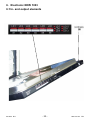
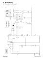
8. Schaltpläne
8.1 Stromlaufplan (Beispiel)
09.2002 R.K.
-39
22 -
599 515 183
EN
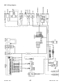
8.2 Wiring diagram
09.2002 R.K.
-40
23 -
599 515 183
EN