1
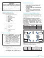
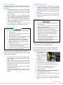
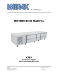
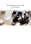
R-290 ITW Refrigeration ITW Refrigeration ITW Refrigeration Form Number TR35957 (REV. 08-03-15) Part Number 375-60325-00 TABLE OF CONTENTS KEY TERMS .............................................................................................................................................................. 2 REQUIRED TOOLS LIST ............................................................................................................................................ 2 BEWARE OF IGNITION SOURCES ............................................................................................................................. 3 GENERAL PRECAUTIONS ......................................................................................................................................... 3 TROUBLESHOOTING THE REFRIGERATION SYSTEM ............................................................................................... 3 LEAK CHECKING SYSTEM ......................................................................................................................................... 4 ACCESSING THE REFRIGERATION SYSTEM .............................................................................................................. 4 REFRIGERANT RECOVERY ........................................................................................................................................ 4 RECOVERING R290 WITHOUT A RECOVERY MACHINE ........................................................................................... 5 VENTING OF R290 (PROPANE) REFRIGERANT ........................................................................................................ 5 REPAIR OF LEAKS ..................................................................................................................................................... 5 SYSTEM EVACUATION ............................................................................................................................................. 6 CHARGING THE SYSTEM.......................................................................................................................................... 6 REMOVE ACCESS PORTS ......................................................................................................................................... 7 REPAIR OF ELECTRICAL COMPONENTS ................................................................................................................... 7 1 KEY TERMS: Lower Explosive Limit (LEL) – The lowest concentration of a gas or vapor in the air capable of producing a flash fire in the presence of an ignition source (arc, flame, heat). A concentration lower than the LEL is not rich enough to burn. The LEL of R-290 (propane) is 2.1% concentration of air. Upper Explosive Limit (UEL) – The highest concentration of a gas or vapor in the air capable of producing a flash of fire in the presence of an ignition source (arc, flame, heat). Concentration higher than the UEL is too rich to burn. The UEL for R-290 (propane) is 9.5% concentration of air. EPA/SNAP – Environmental Protection Agency/Significant New Alternative Policy. EPA/SNAP has approved R-290 (propane) refrigerant for use in new equipment. Global Warning Potential (GWP) – Natural hydrocarbon refrigerants like R-290 (propane) have a very low GWP of less than 3. Hydrocarbon Refrigerants (HC) – Hydrocarbon refrigerants are natural, non-toxic, non-ozone depleting replacements for CFC refrigerants. Ozone Depletion Potential (ODP) - Natural hydrocarbon refrigerants like R-290 (propane) have an ODP of zero. Flash Point –Flash point is the minimum temperature at which a substance will burn with an ignition source. The flash point of R-290 (propane) is -150F. Auto Ignition Temperature – The auto ignition temperature is the temperature at which a fuel will ignite without the need for a spark or flame. In respect to auto ignition temperature of R-290 is 896⁰F. Well Ventilated - Any area or space where air flow can enter and exit freely. Confined Space - Per OSHA a confined space is defined as: Large enough for an employee to enter fully and perform assigned work. Not designed for continuous occupancy by the employee. Has a limited or restricted means of entry or exit. Personal Protection Equipment (PPE) – This is list is not meant to be all encompassing but should include: safety glasses, knee protection or kneeling aid, first aid kit, fire extinguisher, insulated screwdriver set, LOTO kit, ear plugs, slip resistant black leather safety toe shoes, electrical glove kit (rubber glove and “goatskin protector”), cut resistant gloves, cut resistant sleeves, heat resistant sleeves, GFCI cord set, fall prevention kit, nitrile gloves, chemical googles, ARC flash barrier tape, hard hat with ARC flash rated face shield, and ARC flash rated balaclava. REQUIRED TOOL LIST: Combustible gas leak detector Spark resistant tools PPE (Personal Protection Equipment) Dedicated R-290 manifold gauges Class B dry powder fire extinguisher Empty recovery cylinder Digital thermometer/meter Vacuum Pump 2 GENERAL PRECAUTIONS (Cont): For models containing R290 (Propane) as a refrigerant, all instructions labeled on the unit must be closely followed. Service and repair must be performed by qualified refrigeration technicians familiar with applicable safety standards for flammable refrigerants. Technician must use appropriate personal protective precautions to avoid risk of fire or explosion. Beware of flammable materials present in the work area. Extinguish ignition sources within 10 feet of the work area if possible. A Class B dry powder type fire extinguisher must be kept nearby. Technicians must only use spark-resistant tools. Always use appropriate PPE (Personal Protection Equipment). BEWARE OF IGNITION SOURCES: Examples of potential ignition sources: A spark from an electrical source such as: o Contactors o Relay o Defrost heaters o Condensate pan heaters o Door Switches o Light bulbs o Electrical outlets o Switches o Electric Drill o Static electricity Open flame ignition sources such as: o Fryers o Cigarettes/lighters o Gas appliances o Griddles Tools o Non-spark resistant tools o Heat guns o Torches GENERAL PRECAUTIONS: Proper care must be taken to avoid any damage to refrigeration system including refrigerant tubing, condenser, evaporator coils during handling, moving, and installation and cleaning as it may cause risk of refrigerant leak, fire or explosion. If damaged, unit must be moved to well ventilated area away from any ignition sources. You must have a combustible gas leak detector on at all times TROUBLESHOOTING THE REFRIGERATION SYSTEM: Troubleshooting of the refrigeration system should always be done using temperature sensors as outlined below. Manifold gauges should be used for refrigerant recovery and recharge only. Trouble Shooting Refrigeration System by Temperature: Use the below table and corresponding chart to aid in troubleshooting a Traulsen refrigeration system with the use of thermometers. Place thermometer probes at corresponding locations as indicated by letter markers and plug values into formulas. MEASUREMENT FORMULA Condenser Split (A + B)/2)-Ambient Temp Sub-cooling (A + B)/2)-B Superheat D-C TRAULSEN SPEC 30F 4F-12F 5F-7F Inlet of Condenser Outlet of Evaporator Outlet of Condenser Inlet of Evaporator NOTE: Unit must be running for at least 5-10 minutes before checking temperatures. Insulate sensing bulb of thermometer for most accurate readings. Interpreting Line Temperature Differences: The following precautions should be taken when working with an R-290 refrigeration system: • Notify all persons in the immediate area that you are working with a flammable refrigerant. Superheat Subcooling Diagnosis Above 7F Below 4F Refrigerant Charge is Low Below 5F Above 12F System Overcharged Above 7F Above 12F Restriction in High Side or TXV • Do not work with R-290 in a confined space and insure the work area is well ventilated. 3 LEAK CHECKING SYSTEM: You must have a combustible gas leak detector on at all times. You must have a Class B dry powder fire extinguisher available at all times. Notify all persons in the immediate area that you are working with a flammable refrigerant. This procedure requires the use of refrigerants. Be certain the work is well ventilated. Safety goggles should be worn since refrigerants may cause burns to the skin. Disconnect the electrical power to the machine and follow lockout/tagout procedures. Do not pressurize system above 150 psig prior to evacuation or during leak procedure. Never use any dyes or other contaminants when working with the R-290 refrigeration system. Refer to serial tag for maximum system pressures. A number of means for leak detection may be considered during on-site work: Bubble test Holding pressure test Combustible gas detection ACCESSING THE REFRIGERATION SYSTEM: You must have a combustible gas leak detector on at all times. You must have a Class B dry powder fire extinguisher available at all times. Notify all persons in the immediate area that you are working with a flammable refrigerant. This procedure requires the use of refrigerants. Be certain the work is well ventilated. Safety goggles should be worn since refrigerants may cause burns to the skin. Disconnect the electrical power to the machine and follow lockout/tagout procedures. Do not pressurize system above 150 psig prior to evacuation or during leak procedure. REFRIGERANT RECOVERY: You must have a combustible gas leak detector on at all times. You must have a Class B dry powder fire extinguisher available at all times. Notify all persons in the immediate area that you are working with a flammable refrigerant. This procedure requires the use of refrigerants. Be certain the work is well ventilated. Safety goggles should be worn since refrigerants may cause burns to the skin. Disconnect the electrical power to the machine and follow lockout/tagout procedures. Do not pressurize system above 150 psig prior to evacuation or during leak procedure. Special attention is required when recovering R-290. ONLY explosion proof HC recovery machines are suitable for recovery of R-290. The recovery cylinder must be suitable for the refrigerant used and designated for R-290 only. Never mix R-290 with other refrigerants. Ensure that all connections are secure and there are no potential ignition sources nearby. Make sure that you are NOT in a confined space. Make sure that you are in a well ventilated space. It is recommended that a safety zone of at least 10’ in diameter is maintained around the work area. When possible extinguish all ignition sources. After all connections are made you will need to check these connections with your combustible gas leak detector to assure that there is no R-290 propane leaking. If there is not an explosion proof HC recovery available for use with R-290, follow the procedure outline in the RECOVERYING R-290 WITHOUT a RECOVERY MACHINE section of this manual. Piercing valves can be used to access the refrigeration system. Access ports should be temporarily placed on the process tube (suction and/or liquid line) as close to the end of the process tube as possible. Never leave access ports of any kind on an R-290 refrigeration system. 4 RECOVERING R290 WITHOUT A RECOVERY MACHINE: You must have a combustible gas leak detector on at all times. You must have a Class B dry powder fire extinguisher available at all times. Notify all persons in the immediate area that you are working with a flammable refrigerant. This procedure requires the use of refrigerants. Be certain the work is well ventilated. Safety goggles should be worn since refrigerants may cause burns to the skin. Disconnect the electrical power to the machine and follow lockout/tagout procedures. Do not pressurize system above 150 psig prior to evacuation or during leak procedure. According to Environmental Protection Agency Significant New Alternative Policy, R-290 can be vented to the atmosphere. Use the following process to recovery and vented R-290 with the use of a recovery machine. 1. Evacuate the empty recovery cylinder into a vacuum 2. Using an accurate refrigerant scale, zero out the refrigerant scale and weigh the empty recovery cylinder prior to adding refrigerant gauges or hoses, notate this weight. 3. VENTING OF R290 (PROPANE) REFRIGERANT: You must have a combustible gas leak detector on at all times. You must have a Class B dry powder fire extinguisher available at all times. Notify all persons in the immediate area that you are working with a flammable refrigerant. This procedure requires the use of refrigerants. Be certain the work is well ventilated. Safety goggles should be worn since refrigerants may cause burns to the skin. Disconnect the electrical power to the machine and follow lockout/tagout procedures. Do not pressurize system above 150 psig prior to evacuation or during leak procedure. 1. Venting inside a building is not permissible under any circumstance. 2. Venting must not be to a public area or where people are unaware of the procedure. 3. The technician responsible for venting R290 must make all persons in the immediate area aware a flammable gas is being released to the atmosphere. 4. Ensure there are no ignition sources within 10ft of the area you are venting R290. 5. Ensure that all local legislation addressing safety of hazardous or flammable substances are satisfied. Note: The State of California does not allow R-290 to be vented. Consult factory. Securely connect the evacuated cylinder to the refrigeration system using refrigerant gauges and hoses. 6. 4. Open the refrigerant gauges to allow refrigerant to flow through the gauges to the recovery cylinder. REPAIR OF LEAKS: 5. Once the pressures have equalized, valve off the refrigerant gauges and the recovery cylinder securely. 6. Carefully remove the refrigerant hose from the recovery cylinder. 7. Zero out the refrigerant scale and weigh the recovery cylinder, notate this weight. Subtract the weight notated from line 2 from line 7. This is the amount of refrigerant recovered into the cylinder. 8. A recovery cylinder containing R290 can be vented outdoors. See VENTING R-290 for instructions on venting R-290. 9. After venting the refrigerant, purge the recovery cylinder with nitrogen at a flow rate of 5PSGI for the liquid port of the recovery cylinder for 2 minutes outdoors, 10 feet away from any structures or ignition sources. 10. Repeat steps 1-9 until the recovery cylinder and the system equalize into a vacuum. NOTE: Trace amounts of R290 will remain trapped in the POE oil of the compressor. Ensure you are not venting R290 into a low lying area. You must have a combustible gas leak detector on at all times. You must have a Class B dry powder fire extinguisher available at all times. Notify all persons in the immediate area that you are working with a flammable refrigerant. This procedure requires the use of refrigerants. Be certain the work is well ventilated. Safety goggles should be worn since refrigerants may cause burns to the skin. Disconnect the electrical power to the machine and follow lockout/tagout procedures. Do not pressurize system above 150 psig prior to vacuation or during leak procedure. Brazing and soldering: It is of utmost importance to properly repair refrigerant leaks as soon as they are discovered. If they cannot be repaired immediately, the refrigerant charge should be removed from 5 REPAIR OF LEAKS [Cont]: the system until the point at which the leak can be repaired. A number of considerations are relevant when attempting to repair a leak; Repair the leak properly – this means removing the refrigerant, examining the leak source, determining the reason for the leak and carrying out the proper course of action. Before repairing the leak, ensure that the refrigerant has been removed and the system flushed with nitrogen, especially if brazing is to take place. Always run low pressure nitrogen through the system when brazing this reduces the risk of oxidation and combustible gas ignition. It is absolutely not acceptable to leave line tap valves or piercing valves attached to the system. SYSTEM EVACUATION [Cont]: CHARGING THE SYSTEM: SYSTEM EVACUATION: You must have a combustible gas leak detector on at all times. You must have a Class B dry powder fire extinguisher available at all times. Notify all persons in the immediate area that you are working with a flammable refrigerant. This procedure requires the use of refrigerants. Be certain the work is well ventilated. Safety goggles should be worn since refrigerants may cause burns to the skin. Disconnect the electrical power to the machine and follow lockout/tagout procedures. Do not pressurize system above 150 psig prior to evacuation or during leak procedure. After the system has been sealed and leak checked, it is necessary to evacuate it in order to remove air, moisture, and unwanted residual refrigerant. It is necessary to purge the system with nitrogen. This is necessary to prevent flammable mixtures from occurring. When connecting the hoses between the system, gauge manifolds, and vacuum pump, ensure that the connections are secure and there are no potential ignition sources nearby. Ensure that the pump discharge is in an area free of potential ignition sources. Ensure that a micron gauge is used since conventional manifold gauges may not provide a proper reading. The system should be evacuated to the desired pressure (typically 250 microns or less) and then left to stand for 15 minutes to ensure that the entire refrigerant charge has been removed from the oil and any residual moisture has been evaporated from the system. Ensure that the vacuum pump is of good quality and of appropriate capacity for the system, and the oil level is correct. You must have a combustible gas leak detector on at all times. You must have a Class B dry powder fire extinguisher available at all times. Notify all persons in the immediate area that you are working with a flammable refrigerant. This procedure requires the use of refrigerants. Be certain the work is well ventilated. Safety goggles should be worn since refrigerants may cause burns to the skin. Disconnect the electrical power to the machine and follow lockout/tagout procedures. Do not pressurize system above 150 psig prior to vacuation or during leak procedure. Dial-a-charge cylinders, with a sight glass, should not be used to charge systems with flammable refrigerant. The same charging procedures are used with R-290 refrigerants as with any other type of refrigerant, except certain considerations are important: 1. The Process Tube needs to be extended. Remove the crimped tubing and piercing or saddle valve from the process tube. Extend the process tube a minimum of 12”. Crimp and braze the process tube extension. Install piercing or saddle valve just after last crimp. 2. Evacuate the system following the SYSTEM EVACUATION: section in this document. 3. Charge the System. DO NOT OVERCHARGE A SYSTEM USING R-290. You must weigh in the exact charge. Prior to charging, ensure the system has been leak checked. Hoses or lines should be a short as possible to minimize the amount of refrigerant contained in them. 6 CHARGING THE SYSTEM [Cont]: Evacuate the hoses and manifold prior to charging to avoid contamination of the refrigerant. Upon completion of charging, a further leak check must be carried out prior to leaving the site. After charging, carefully disconnect the hoses, attempting to minimize the release of refrigerant. After charging all access ports must be removed following the REMOVE ACCESS PORTS section in this document. REMOVE ACCESS PORTS: You must have a combustible gas leak detector on at all times. You must have a Class B dry powder fire extinguisher available at all times. Notify all persons in the immediate area that you are working with a flammable refrigerant. This procedure requires the use of refrigerants. Be certain the work is well ventilated. Safety goggles should be worn since refrigerants may cause burns to the skin. Disconnect the electrical power to the machine and follow lockout/tagout procedures. Do not pressurize system above 150 psig prior to vacuation or during leak procedure. REPAIR OF ELECTRICAL COMPONENTS [Cont]: All electric al devices must not be potential ignition sources. This is achieved through a number of ways. Using components that do not produce arcs, sparks, etc. Using components that are positioned in a location where leaked refrigerant cannot and will not reach in the event of a leak. When working on such electrical components, it is essential to ensure that: Faulty components that are intended not to spark are not replaced by components that do spark. Faulty components that are intended not to spark are not modified in a way such that they do spark. It is important to check all components to ensure that no unauthorized modifications have been made to the equipment, there is no ageing, wear, mechanical stresses or there are no potential sources of ignition. Electrical parts that should be checked include: Terminal connections should be tightly affixed and not loose, which could result in unintended arching. Protective conductor connections should be checked each time a repair is mad. Wiring and cabling should also be checked to make sure they are not damaged. Do NOT leave piercing valves on this system. If you cannot finish the repair you will need to use Lock/Out Tag/Out procedures. 1. Pinch line off just before the temporary access port three times using a crimper tool. 2. Verify that there are no leaks. 3. Remove the piecing valve/temporary access port. 4. Cut off the copper tubing between the location of the temporary access port removed in step 3 and the crimps made in step 1. 5. Braze open end shut. 6. Leak check the system following the LEAK CHECKING SYSTEM section in this document. REPAIR OF ELECTRICAL COMPONENTS: Disconnect the electrical power to the machine and follow lockout/tagout procedures. You must have a combustible gas leak detector on at all times. Before you start work on electrical components: Per ANSI/UL 471, Ed: 10th, SB6.2.4, component parts shall be replaced with like components WHEN IN DOUBT, ALWAYS USE OEM COMPONENTS. 7 8 R-290 ITW Refrigeration ITW Refrigeration ITW Refrigeration HOURS OF OPERATION: Monday thru Friday 7:30 am - 4:30 pm CST 4401 Blue Mound Road Fort Worth, TX 76106 Phone 800.825.8220 Fax 817.740.6757 Traulsen.com & Kairak.com © 2015 Traulsen - All Rights Reserved 9