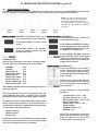
1
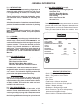
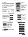
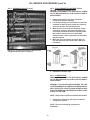
Traulsen Refrigeration
SERVICE MANUAL #07
Instructions For The Installation,
Troubleshooting And Repair Of Traulsen
epicon® Equipped Blast Chiller Models
Undercounter Model TBC5
Reach-In Model TBC13
Roll-In/Roll-Thru Models TBC1H, TBC1HR, TBC2H & TBC2HR
-NOTICE-
This Manual is prepared for the use of trained Authorized Traulsen Service Agents and should not be used by
those not properly qualified. This manual is not intended to be all encompassing, but is written to supplement
the formal training, on-the-job experience and other product knowledge acquired by Authorized Traulsen
Service Agents. Before proceeding with any work, you should read, in its entirety, the repair procedure you
wish to perform to determine if you have the necessary tools, instruments and skills required to perform
the procedure. Procedures for which you do not have the necessary tools, instruments and skills should
be performed only by a trained Authorized Traulsen Service Agent.
Reproduction or other use of this Manual, without the express written consent of Traulsen, is prohibited.
FORM NUMBER TR99999 - REV. 8/13
I. TABLE OF CONTENTS
I. TABLE OF CONTENTS
1
VIII. SERVICE PROCEDURES
a-Temperature Sensors
b-Expansion Valve
2
c-Door Perimeter Heaters
2
d-Compressor
2
e-Condenser Fan Assembly
2
f-Condenser Coil
2
g-Pressure Control
2
h-Evaporator Coil
2
i-Filter/Drier
j-Evaporator Blower
DATA
k-Checking For Leaks
3
l-Evacuating The System
3
m-Charging The System
3
n-System Clean-Up
o-Replacing The Door Gasket
II. GENERAL INFORMATION
a-Introduction
b-Operation
c-Cleaning
d-Applicable Models
e-Wiring Diagrams
f-Tool Requirements
g-The Serial Tag
III. SPECIFICATIONS/OPERATING
a-Product Specifications
b-Operating Data
c-Refrigeration System Installation
IV. SERVICING THE EPICON CONTROL
9
9-10
10
10-11
11
11
11
11
12
12
13
13
14
14
15
IX. WIRING DIAGRAMS - TBC5
16
X. WIRING DIAGRAMS - TBC13
17
XI. WIRING DIAGRAMS - TBC1H MODELS
18
V. CONTROL ARCHITECTURE
XII. TROUBLESHOOTING
19-20
XIII. TBC5 REPLACEMENT PARTS LIST
21
XIV. TBC13 REPLACEMENT PARTS LIST
22
XV. TBC1H REPLACEMENT PARTS LIST
23
a-Overview
b-The Toolbox
4
4
c-Setting The Clock
d-Service Menu
e-Service Menu Features
4
4
5
a-Controller Board
6
VI. COMPONENT FUNCTION
7
VII. SEQUENCE OF OPERATION
a-Refrigeration System
b-Refrigeration System (BC compressor on TBC1H only)
c- IDLE Mode
d- Hold Mode
e-By Time Chill/Freeze Mode
f-By Temp Chill/Freeze Mode
g-By Product Chill/Freeze Mode
h-Defrost Mode`
8
8
8
8
8
9
9
9
Visit the Resource Center @ www.traulsen.com to
review the Operator’s Video for this product.
-1-
II. GENERAL INFORMATION
II. f - TOOL REQUIREMENTS (cont’d):
II. a - INTRODUCTION:
Blast Chillers are food processing refrigerators designed for rapid chilling of product from 140 F to 40
F in approximately 90 minutes, for reheating and/or
serving at a later time.
These models aid in preserving food quality, texture
and nutritional value, in addition to enhancing food
safety.
All of the information, illustrations and specifications
contained within this manual are based on the latest
product information available at the time of printing.
II. g - THE SERIAL TAG:
The serial tag is a permanently affixed sticker on which is
recorded vital electrical and refrigeration data about your
Traulsen product, as well as the model and serial number.
This tag is located inside all blast chiller models. An example is shown below.
II. b - OPERATION:
Refer to the instructions contained in the Owner’s
Manual, form number TR35938, for specific operating
instructions.
II. c - CLEANING:
Detailed cleaning instructions are included with each
unit, however, special care MUST be given to the condenser coil(s). These must be cleaned WEEKLY. This
surface must be kept free of dirt and grease for proper
system operation. This can be done with a vacuum
cleaner using a brush attachment, or a stiff brush or
wisk broom. Care must be taken not to damage the
condenser coil fins. For more information please refer
to section V. a, V. e, and V. f of the Blast Chill Owner’s
Manual.
FORT WORTH, TX.
SERIAL VOLTS MODEL
Hz PH
TOTAL CURRENT
AMPS
MINIMUM CIRCUIT
AMPS
MAXIMUM OVERCURRENT PROTECTION
LIGHTS
WATTS
HEATERS
AMPS
AMPS
REFRIGERANT
DESIGN PRESSURE
TYPE
HIGH
OZ
LOW
REFRIGERANT
DESIGN PRESSURE
TYPE
HIGH
OZ
LOW
370-60294-00 REV (A)
II. d - APPLICABLE MODELS:
This manual applies to the following Traulsen models:
• Refrigeration Reclaiming Equipment
• Acetylene Torch
• Nitrogen Bottle With Gauges
• Refrigeration Gauge Manifold
•Dial-a-Charge
• Valve Core Removal Kit
• Vacuum Pump
TBC5 Undercounter Blast Chiller
TBC13 Reach-In Blast Chiller
TBC1H & TBC2H Roll-In Blast Chillers
TBC1HR & TBC2HR Roll-Thru Blast Chillers
PLEASE NOTE: This manual refers to the above
models built after June 2012, equipped with the epicon® control. For information regarding models built
prior to that date please contact the factory.
READING THE SERIAL TAG
• Serial = The permanent ID# of your Traulsen
• Model = The model # of your Traulsen
• Volts = Voltage
• Hz = Cycle
• PH = Phase
• Total Current = Maximum amp draw
• Minimum Circuit = Minimum circuit required
• Lights = Light wattage
• Heaters = Heater amperage
• Refrigerant = Refrigerant type used
• Design Pressure = High & low side operating
pressures and refrigerant charge
• Agency Labels = Designates agency listings
II. e - WIRING DIAGRAMS:
Refer to the wiring diagrams on pages 16 thru 18 for
any service work performed on the unit. Should you
require another copy, please contact Traulsen Service
at (800) 825-8220, and provide the model and serial
number of the unit involved.
II. f - TOOL REQUIREMENTS:
For most jobs a standard set of hand tools, a VOM
with AC current tester, electrically conductive field
service grounding kit, along with a temperature tester
or thermometer are adequate. However in some cases
the following additional tools may be required as well:
-2-
III. SPECIFICATIONS/OPERATING DATA/INSTALLATION
III. a - PRODUCT SPECIFICATIONS:
DIMENSIONS
TBC5
Length - Overall in.
54
Depth - Overall in.
34-7/16
Height - Overall in.
34
Capacity 12 x 20 Pans 10
Capacity 18 x 26 Pans 5
Capacity Product Weight 100 lbs.
TBC13TBC1HTBC1HR TBC2HTBC2HR
41
48-1/2
48-1/2
48-1/2
48-1/2
34-1/2
37-5/8
41-1/4
71-5/6
75-1/4
74
90-3/8
90-3/8
90-3/8
90-3/8
26
1 Rack 1 Rack
2 Racks 2 Racks
13
1 Rack 1 Rack
2 Racks 2 Racks
200 lbs. 300 lbs. 300 lbs.
600 lbs. 600 lbs.
III. b - OPERATING DATA:
DATA
TBC5 TBC13TBC1HTBC1HR TBC2HTBC2HR
Single or Dual System
Single Dual
Dual
Dual
Dual
Dual
Remote Chill Compressor n/a
No
Yes
Yes
Yes(2)
Yes(2)
H.P.1
1
1/2
1/2
1/2
1/2(2)
1/2(2)
BTU/HR1
4300
2820
2820
2820
2820(2) 2820(2)
H.P.2
n/a
1-1/4
4
4
4(2)
4(2)
BTU/HR2
n/a
5710
18,700 18,700
18,700(2) 18,700(2)
Refrigerant Type
R-404A R-404A R-404A R-404A
R-404A R-404A
Refrigerant Charge oz. 29
31
25
25
25(2)
25(2)
Refrigerant Charge2
n/a
45
See Note3 See Note3 See Note3 See Note3
Condenser RLA1
11.7
5.1
10.5
10.5
10.5(2) 10.5(2)
Condenser RLA2
n/a
9.3
See Note3 See Note3 See Note3 See Note3
Unit Voltage
115
208/115 115
115
115(2)
115(2)
Phase
1111 11
Hz
60606060 6060
Full Load Amps
13.3
13.4
14.9
14.9
14.9(2) 14.9(2)
NEMA Plug Type
5-20
14-20
Hard Wire Hard Wire Hard Wire Hard Wire
1= Self-Contained Holding or Primary Compressor.
2= Blast Chilling or Secondary Compressor.
3= Varies with remote system.
III. c - REFRIGERATION SYSTEM INSTALLATION:
All Traulsen blast chillers, with the exception of model TBC5, require
the use of a floor drain or floor mounted condensate evaporator for
condensate removal. Refer to Section IV. h of the blast chill owner’s
manual for more information.
Remote refrigeration installation requirements apply only to models
TBC1H/TBC1HR and TBC2H/TBC2HR. A remote condensing unit, operating on R-404A refrigerant, is required for Blast Chill operation on
these models. The remote condensing unit(s) should be capable of
providing 18,700 BTU/hr @ -10°F evaporator temperature and 90°F
ambient.
Air-cooled and water-cooled remote condensing units are available
from Traulsen as an optional accessory. Please note that these
should be adequate for any installation within a 25 foot radius from
the cabinet. Beyond this distance, the actual capacity of the remote
condensing unit and line sizing may change depending upon the
length and layout of the connecting piping from the remote condensing unit to the Blast Chiller. These utilize a 1/2” liquid and 1-1/8”
suction lines. Proper specification of the remote condensing unit
needed and line sizing should be defined by a qualified refrigeration
engineer or technician, based on the jobsite installation needs.
The low pressure cut-out of the remote condensing unit should be
adjusted to obtain an evaporator coil temperature NO LOWER THAN
-15°F. If the length of the connecting piping is 40 feet or less, the
condensing unit low pressure cut-out settings will be approximately
15 +/- 2 PSIG cut-out and 25+/- 3 PSIG cut-in.
For more information please contact the factory.
-3-
IV. SERVICING THE EPICON CONTROL
IV. a - OVERVIEW:
Traulsen’s TBC Series blast chillers are equipped with
the epicon microprocessor control. This is protected
from damage by a surrounding heavy gauge metal bezel. It includes several diagnostic features built within
the TOOLBOX’s SERVICE menu. The control itself has
no serviceable parts. Should you encounter a faulty or
damaged control, it will need to be replaced.
IV. c - SETTING THE CLOCK (continued):
To adjust the Date and time settings:
1) 2) 3) 4) IV. b - THE TOOLBOX:
The TOOLBOX can be accessed by pressing the
MANUAL tab, and then the TOOLBOX icon on top of
the MANUAL menu screen.
From the MANUAL
menu screen press
the TOOLBOX icon.
Press DAY - MONTH - YEAR - HOUR - MINUTE as needed (after doing so the field will be highlighted).
Toggle the LEFT/RIGHT
arrows at bottom to adjust this parameter
Proceed to the next parameter.
Press SAVE TIME to save
these settings.
IV. d - SERVICE MENU:
Press SERVICE to access the service menu. Note that
this is password protected. The factory default code
is 4401. Enter the access code to proceed.
The control will now display the TOOLBOX menu. It
includes three security levels.
Press USER for operator level
access. This provides open
access allowing you to: Set the
Clock, Adjust Defrost Time and
Settings, Download Cycle Data,
Search Chill Cycle History, and
Upload Recipes to the
PRODUCT menu.
Press SUPERVISOR for
supervisor access. Note
that this not intended for
every day access and
adjustments and so is
password protected
Enter your access code to
proceed. The factory
default code is 1234. This can
be changed in the SUPERVISOR level.
The SERVICE menu will appear.
IV. c - SETTING THE CLOCK:
Begin by pressing MANUAL - TOOLBOX - USER, then
press SET DATE/TIME. The display will change to the
SET DATE/TIME screen.
-4-
IV. SERVICING THE EPICON CONTROL (cont’d)
IV. e - SERVICE MENU FEATURES:
CALIBRATE: This features allows for calibration of the touchscreen’s accuracy. Press CALIBRATE than each of the
five plus symbols (+) as closely as possible to do so. Note use of a stylus is highly recommended.
NOTE: The units are calibrated from the
factory and should only be recalibrated
if necessary. Exercise extreme caution
when recalibrating as improper inputs while
calibrating can result in difficultly navigating
the control.
Touch
Point 1
Touch
Point 2
Touch
Point 3
Touch
Point 4
PRINTERS: This feature allows you to
check each printer for proper operation.
Press PRINT CHART to test the record
printer.
Press PRINT LABEL to test the label
printer on models supplied with the
optional label printer.
TEMPERATURES:
Displays key temperature sensor data. Expected values
for each should be in similar to those shown below...
PARAMETERS:
Press START DEFROST to initiate an
on demand defrost cycle.
Press DOWNLOAD SERVICE DATA to
transfer all temperature data (as shown
on the TEMPERATURE menu) through
the USB port to a thumb drive.
Press DOWNLOAD RAW DATA to
transfer all data in memory through the
USB port to a thumb drive. NOTE: this
feature requires use of special software
available from Traulsen.
DIAGNOSTICS:
Press each OUTPUT one at a time in
order to change test status from OFF
to ON. Record the reading and then
turn the OUTPUT off before proceeding
to the next one.
AMBIENT66°F
CABINET
34°F
MAINT EVAP IN
63°F
MAINT EVAP CORE 42°F
BLAST EVAP IN 32°F
BLAST EVAP CORE 37°F
BLAST EVAP OUT
32°F
BLAST LIQUID LINE 66°F
MAINT LIQUID LINE 66°F
SOFTWARE: Select this feature when updating the control’s
operating software.
The current software versions are displayed at the top
of the TOOLBOX main menu. Contact Traulsen at (800)
825-8220 to verify if you have the latest software versions.
To update the control, insert a thumb drive containing the
latest software into the USB port. Note all files must be
located in the root directory. Updates should be performed
in the following order (if necessary)...
Touch
Point 5
Update I/O Board
Update UI Board
Update HTML
Follow the instructions provided with the software update
and any on screen instructions. Do not remove the thumb
drive until all updates have been completed.
-5-
NOTE: If you do not turn each OUTPUT
off before proceeding to the next one
you can potentially cause damage to
that component.
Normal readings for each OUTPUT
should be...
LS EVAP FANS = 3.7A +/- .55A
HS EVAP FANS = 3.9A +/- .15A
MAINT COND FAN = 1.15A +/- .25A
BLAST COND FAN =
MAINT COMP = 7.5A +/- 1.5A
BLAST COMP =
DEFROST VALVE = n/a
BUZZER = n/a
NOTE: The maintenance compressor
has an anti-cycling feature of 1-minute.
Allow the cabinet to idle for at least
1-minute before beginning a test.
V. CONTROL ARCHITECTURE
LEGEND
1. UI Power
2. USB Port (used)
3. USB Port (unused)
tion
4. Label Printer Power
5. Label Printer Communication
6. Paper Printer Power
7. Paper Printer Communica-
-6-
VI. COMPONENT FUNCTION
Compressor
Pumps refrigerant through refrigeration lines and components.
Condenser Fan
Draws air across condenser coil to aid in removing heat from the refrigerant and moves air across compressor to aid in cooling the compressor.
Dual Pressure Control
(TBC1H & TBC2H only)
Low side monitors suction pressure at compressor. Shuts compressor OFF when low pressure setting is reached (cut-out). Allows compressor to run when
pressure rises to cut-in setting.
High side monitors discharge pressure at compressor. Shuts compressor OFF when high side pressure setting is reached (cut-out). Allows compressor to run when pressure returns to cut-in setting.
The differential is the difference in pressure between open and closed states of the pressure switch.
Start Capacitor
Wired in series with the start windings to help start compressor motor.
Run Capacitor
Continually in circuit to help compressor motor during operation.
Thermal Overload
Removes power from compressor if the internal temperature of the compressor becomes too high (auto reset).
Start Relay
Senses current of run winding of compressor motor. Normally open contacts close when run winding draws a high amperage at start and brings the start
capacitor and start windings into the circuit. As the motor reaches operating speed (less amperage through run winding), the normally open contacts open and removes the start capacitor and start windings from the circuit.
Evaporator Fan
Draws air from the cabinet and moves air through the evaporator coil.
Defrost Heater
Defrosts evaporator coils and prevents water droplets from evaporator coil from freezing before they can drain to the condensate pan. Operates only during defrost cycle.
Air Temperature Sensor
Monitors air temperature inside the cabinet.
Coil Temperature Sensor
Monitors the suction line temperature at evaporator during defrost cycle.
Food Temperature Probe
Monitors temperature of food product.
Solenoid Valve
Normally closed. When energized, allows refrigerant to flow from receiver to evaporator coil.
Door Perimeter Heater
Prevents condensate on door frame.
Controller
Performs the following functions:
a) Displays all data for the current mode of operation.
b) Cycles refrigeration system to maintain cabinet temperature.
c) Monitors power failures.
Power Supply Boards
Provides DC voltage to control system.
Relay Board
Performs the following functions:
a) Cycles fans.
b) Controls outputs to heaters and compressor relays.
Thermal Fuse
TBC1H, TBC1HR, TBC2H and TBC2HR only. Monitors cabinet air temperature. Opens circuit to defrost heater if cabinet temperature exceeds 230°F.
-7-
VII. SEQUENCE OF OPERATION
VII. a - REFRIGERATION SYSTEM - HOLD MODE:
1. The controller monitors the air temperature and senses a need for cooling.
a) The relay that controls the compressor is energized.
3. The expansion valve monitors the evaporator superheat and meters the amount of refrigerant entering the evaporator.
4. The controller senses the air temperature
requirements have been met.
a) De-energizes the relay that controls the compressor.
5. Unit is cycled by controller.
VII. d - HOLD MODE (cont’d):
1. Unit is in IDLE mode.
2. Hold mode is initiated.
NOTE: When the hold mode is initiated, two timers
run. One tracks the time in the hold mode and the
other tracks the time since the last defrost (hold
mode defrosts at a programable interval).
a) The refrigeration system will cycle on the air temperature of the cabinet.
1-ON at the set-point plus differential.
2-OFF when set-point reached.
b) The hold mode has an automatic defrost
cycle. The operator can program the
interval between defrost cycles to suit their operational needs.
1-When the defrost cycle is complete and the unit returns to the hold mode, the
evaporator fans will not operate until the
coil temperature is below 20°F.
3. Hold mode is terminated by pressing the exit key.
NOTE: If the HOLD MODE is terminated by the operator with the defrost cycle in progress, the defrost
mode will continue until completion before going
into idle mode.
VII. b - REMOTE REFRIGERATION SYSTEM (TBC1H, TBC1HR, TBC2H & TBC2HR only):
1. The controller must be in a chill or hold mode.
2. The controller monitors the air temperature and senses a need for cooling.
a) The relay that controls the solenoid valve is energized.
1-Solenoid valve is energized and refrigerant flows to the evaporator.
2-Fans are operating at high speed.
3. The low pressure switch closes with pressure rise.
a) The compressor motor is energized and refrigerant is pumped through the system.
4. The expansion valve monitors the evaporator superheat and meters the amount of refrigerant entering the evaporator.
5. The controller senses the air temperature
requirements have been met.
a) De-energizes the relay that controls the solenoid valve.
1-Solenoid valve is de-energized and closes. Refrigerant flow to the evaporator stops.
2-Fan operation changes to low speed.
6. Compressor continues to run. Low pressure control opens as pressure drops.
a) Compressor motor de-energized.
7. Unit is cycled by controller.
VII. e - BY TIME CHILL MODE:
1. Unit is in IDLE mode.
2. Chill type is selected and a cycle time is entered then start key is pressed.
3. The refrigeration system will cycle on the
blasting air temperature set-point.
a) ON at the set-point plus differential.
b) OFF when set-point is reached.
4. If SPEED has been selected, the refrigeration system will cycle on the new blasting air
temperature set-point after softchill condition is met, i.e. 70 percent of time has expired.
5. Chill mode is terminated when time expires.
a) Buzzer sounds until muted.
6. At the end of a chill cycle the unit will enter the hold mode.
a) If the end of the chill cycle is acknowledged by pressing the STOP/RESET key, the unit will enter the idle mode.
VII. c - IDLE MODE:
1. Conditions
a) Unit connected to correct voltage.
b) Safety thermostat closed.
2. Door heater energized.
3. Main switch closed - controller energized.
a) Main contactor energized, contacts close.
4. Controller displays main menu.
5. Controller maintains cabinet air temperature at hold mode temperature.
VII. d - HOLD MODE:
Product will be held automatically at chilled temperature when all active probes have reached the target
temperature when in any mode. If a “BY TIME” mode
is selected, the unit enters hold mode automatically
after the time has expired.
VII. f - CHILL OR FREEZE MODE BY TEMP:
1. Unit is in IDLE mode.
2. Chill type is selected and a target temperature is entered then start key pressed and probe
selected.
3. The refrigeration system will cycle on the
blasting air temperature set-point.
4. Chill mode is terminated when all the product probes reach the target chill temperature.
-8-
VII. SEQUENCE OF OPERATION (cont’d)
VIII. SERVICE PROCEDURES
VII. f - CHILL OR FREEZE MODE BY TEMP (cont’d):
NOTE: Once the temperature of the probe reaches
the target temperature the display will alternate with
“DONE”, and the buzzer will sound.
a) At the end of the chill cycle the unit will enter idle mode.
VIII. a - TEMPERATURE AIR SENSORS:
WARNING: DISCONNECT THE ELECTRICAL POWER
TO THE MACHINE AND FOLLOW LOCKOUT/TAGOUT
PROCEDURES.
1.
2.
3.
4. 5.
VII. g - BY PRODUCT CHILL OR FREEZE MODE:
1. Unit is in IDLE mode.
2. Product type is selected.
3. The refrigeration system will cycle on the
blasting air temperature set-point.
4. Chill mode is terminated when pre-programmed condition is met. If product is chilled using BY
TEMP mode, all the product probes have reached
the target chill temperature. Or, if product used
BY TIME, when time expires.
Access the evaporator(s).
Remove the cabinet sensor from the
maintenance evaporator.
Remove coil sensors from both the maintenance and blast chill evaporators.
Remove the food temperature probe receptacle from cabinet ceiling.
Disconnect the sensor/probe wiring assembly connector from the controller.
NOTE: If BY TEMP mode was programmed, once the
temperature of the probe reaches the target temperature the display will alternate with “DONE”, and the
buzzer will sound.
a) At the end of the chill cycle the unit will enter idle mode.
VII. h - DEFROST MODE:
1. The defrost mode can be entered manually from the idle mode or automatically from the hold mode.
2. Defrost cycle length is by set minutes or until the coil temperature reaches set-point.
a) If the defrost mode was entered from the hold mode, the unit will return to the hold mode.
3. After either the time has expired, or evaporator temperature probes reach set-point, defrost heat turns OFF.
6. Reverse the procedure to install replacement sensors.
VIII. b - EXPANSION VALVE:
WARNING: DISCONNECT THE ELECTRICAL POWER
TO THE MACHINE AND FOLLOW LOCKOUT/TAGOUT
PROCEDURES.
WARNING: THIS PROCEDURE REQUIRES THE USE
OF REFRIGERANTS. BE CERTAIN THE WORK AREA IS
WELL VENTILATED. SAFETY GOGGLES AND GLOVES
SHALL BE WORN SINCE REFRIGERANTS MAY CAUSE
INJURY TO THE SKIN.
NOTE: All TBC blast chillers include a hot gas
defrost. Therefore the compressors will operate
during defrost operation.
4. Unit waits for two minutes to allow water to drip
off evaporator coils.
a) Hot gas solenoid OFF.
b) Compressors are OFF.
c) Fans are OFF.
5. Fan Delay. After drip cycle, compressors are enabled but fans stay OFF until the evaporator coil(s) reach 20 degrees F.
1.
2.
3.
4.
5.
Pump-down refrigeration system. Warning, after pump-down, refrigerant lines will contain
pressure.
Access the expansion valve.
Detach expansion valve bulb from suction line.
Remove expansion valve from the liquid line at inlet and outlet of valve.
Install new expansion valve into inlet line and fasten bulb to suction line.
NOTE: Make sure expansion valve bulb is attached
parallel to suction line and makes good contact.
-9-
VIII. SERVICE PROCEDURES (cont’d)
VIII. c - DOOR PERIMETER HEATERS (TBC1H,
TBC1HR, TBC2H and TBC2HR only):
WARNING: DISCONNECT THE ELECTRICAL POWER
TO THE MACHINE AND FOLLOW LOCKOUT/TAGOUT
PROCEDURES.
VIII. b - EXPANSION VALVE (cont’d):
1. 2.
3.
4.
Remove the breaker caps from around the
perimeter of the door opening.
Locate the existing wire connections in the foam insulation at the top center of the door opening under the breaker area and disconnect.
With the ends of the new wire at the top center of the door opening, place the new heater wire
around the perimeter of the door opening under
the breaker caps and secure in place with
aluminum tape. Some replacement of insulation may be required.
Make the wire connections and push back up into the cabinet to allow for breaker caps to be
reinstalled.
NOTE: It is recommended that the filter/drier be
changed when this part is replaced.
5. Reinstall the breaker caps.
VIII. e - COMPRESSOR:
WARNING: DISCONNECT THE ELECTRICAL POWER
TO THE MACHINE AND FOLLOW LOCKOUT/TAGOUT
PROCEDURES.
WARNING: THIS PROCEDURE REQUIRES THE USE
OF REFRIGERANTS. BE CERTAIN THE WORK AREA IS
WELL VENTILATED. SAFETY GOGGLES AND GLOVES
SHALL BE WORN SINCE REFRIGERANTS MAY CAUSE
INJURY TO THE SKIN.
NOTE: This procedure applies to all blast chill models.
1. Access the condensing unit and evacuate the refrigeration system.
NOTE: The use of reclaiming equipment is
mandatory.
-10-
VIII. SERVICE PROCEDURES (cont’d)
VIII. d - COMPRESSOR (cont’d):
2. Disconnect lead wires and conduit at the
compressor junction box.
3. Disconnect suction and discharge lines from the compressor.
4. Remove the compressor.
5. Install new compressor and connect wire leads and conduit at compressor junction box.
6. Install new filter/drier.
7. Evacuate system.
8. Charge system and put unit into operation.
VIII. f - CONDENSER COIL (cont’d):
2. Remove fan guard and fan shroud from
condensing coil.
3. Disconnect inlet and outlet lines at the soldered connections nearest the condenser coil.
4. Remove coil from mounting plate.
5. Reverse procesure to install coil, then proceed to the next step.
VIII. e - CONDENSER FAN ASSEMBLY:
WARNING: DISCONNECT THE ELECTRICAL POWER
TO THE MACHINE AND FOLLOW LOCKOUT/TAGOUT
PROCEDURES.
6. Evacuate the refrigeration system.
NOTE: This procedure applies to all blast chill models.
7. Charge system and put unit into operation.
1. 2.
3.
VIII. g - PRESSURE CONTROL:
WARNING: DISCONNECT THE ELECTRICAL POWER
TO THE MACHINE AND FOLLOW LOCKOUT/TAGOUT
PROCEDURES.
NOTE: It is recommended that the filter/drier be
changed when this part is replaced.
NOTE: The use of reclaiming equipment is
mandatory.
Remove the fan guard from the top of the
condenser assembly.
Remove the screws from the mounting clamps on the front and rear of the motor.
Remove the motor bracket and fan assembly from the mounting bracket.
WARNING: THIS PROCEDURE REQUIRES THE USE
OF REFRIGERANTS. BE CERTAIN THE WORK AREA IS
WELL VENTILATED. SAFETY GOGGLES AND GLOVES
SHALL BE WORN SINCE REFRIGERANTS MAY CAUSE
INJURY TO THE SKIN.
Proceed to perform either step 4a or 4b.
4.a To replace the fan blade only, loosen the set screw that secures the fan blade to the motor
shaft and remove the fan blade from the motor
Install the new fan blade with the set screws
between the motor and the blades.
4.bTo replace the fan motor, disconnect the lead wires from the motor.
5. Reverse the procedure to install.
1.
2.
3.
4.
5.
6.
7.
VIII. g - CONDENSER COIL:
WARNING: DISCONNECT THE ELECTRICAL POWER
TO THE MACHINE AND FOLLOW LOCKOUT/TAGOUT
PROCEDURES.
WARNING: THIS PROCEDURE REQUIRES THE USE
OF REFRIGERANTS. BE CERTAIN THE WORK AREA IS
WELL VENTILATED. SAFETY GOGGLES AND GLOVES
SHALL BE WORN SINCE REFRIGERANTS MAY CAUSE
INJURY TO THE SKIN.
NOTE: This procedure applies to all blast chill models.
1. Evacuate the refrigeration system.
NOTE: The use of reclaiming equipment is
mandatory.
-11-
Pump-down refrigeration system. Warning, after pump-down, refrigerant lines will contain
pressure.
Front seat the suction service valve.
Disconnect wire leads to pressure switch.
Disconnect capillary tube from compressor fitting.
Remove pressure control from mounting bracket.
Replace pressure switch and connect capillary tube to compressor fitting.
Put unit back into operation.
VIII. SERVICE PROCEDURES (cont’d)
VIII. h - EVAPORATOR COIL:
WARNING: DISCONNECT THE ELECTRICAL POWER
TO THE MACHINE AND FOLLOW LOCKOUT/TAGOUT
PROCEDURES.
VIII. j - EVAPORATOR BLOWER:
WARNING: DISCONNECT THE ELECTRICAL POWER
TO THE MACHINE AND FOLLOW LOCKOUT/TAGOUT
PROCEDURES.
WARNING: THIS PROCEDURE REQUIRES THE USE
OF REFRIGERANTS. BE CERTAIN THE WORK AREA IS
WELL VENTILATED. SAFETY GOGGLES AND GLOVES
SHALL BE WORN SINCE REFRIGERANTS MAY CAUSE
INJURY TO THE SKIN.
1.
2.
3. 4.
5.
6.
1.
2.
3.
Access the refrigeration system.
Pump-down refrigeration system. Warning, after pump-down, refrigerant lines will contain
pressure.
Disconnect the suction line at the soldered joint closest to the coil.
NOTE: The use of reclaiming equipment is
mandatory.
5.
6.
7.
8.
Disconnect the liquid line at the expansion valve.
Remove the screws from the coil mounting bracket.
Remove the coil.
Reverse the procedure to install new coil and then proceed to the next step.
NOTE: It is recommended that the filter/drier be
changed when this part is replaced.
9. Evacuate the system.
10. Charge system and put unit back into operation.
VIII. i - FILTER/DRIER:
WARNING: DISCONNECT THE ELECTRICAL POWER
TO THE MACHINE AND FOLLOW LOCKOUT/TAGOUT
PROCEDURES.
WARNING: THIS PROCEDURE REQUIRES THE USE
OF REFRIGERANTS. BE CERTAIN THE WORK AREA IS
WELL VENTILATED. SAFETY GOGGLES AND GLOVES
SHALL BE WORN SINCE REFRIGERANTS MAY CAUSE
INJURY TO THE SKIN.
1.
2.
3.
4. Pump-down refrigeration system. Warning, after pump-down, refrigerant lines will contain
pressure.
Remove filter/drier from liquid line.
Install a new filter/drier.
Evacuate the system.
NOTE: The use of reclaiming equipment is
mandatory.
5. Charge system and put unit back into operation.
-12-
Access the refrigeration system.
Remove the tray slides and pilasters from the interior (TBC5 and TBC13 only).
Remove the evaporator cover and open the evaporator fan panel.
Disconnect the wire leads at the junction box on the top of the unit and pull them into the cavity with the blower.
Remove the bolts that secure the evaporator blower from the housing panel.
Reverse the procedure to install the new
evaporator blower.
VIII. SERVICE PROCEDURES (cont’d)
IX. k - CHECKING FOR LEAKS:
WARNING: DISCONNECT THE ELECTRICAL POWER
TO THE MACHINE AND FOLLOW LOCKOUT/TAGOUT
PROCEDURES.
IX. l - EVACUATING THE SYSTEM:
WARNING: DISCONNECT THE ELECTRICAL POWER
TO THE MACHINE AND FOLLOW LOCKOUT/TAGOUT
PROCEDURES.
WARNING: THIS PROCEDURE REQUIRES THE USE
OF REFRIGERANTS. BE CERTAIN THE WORK AREA IS
WELL VENTILATED. SAFETY GOGGLES AND GLOVES
SHALL BE WORN SINCE REFRIGERANTS MAY CAUSE
INJURY TO THE SKIN.
WARNING: THIS PROCEDURE REQUIRES THE USE
OF REFRIGERANTS. BE CERTAIN THE WORK AREA IS
WELL VENTILATED. SAFETY GOGGLES AND GLOVES
SHALL BE WORN SINCE REFRIGERANTS MAY CAUSE
INJURY TO THE SKIN.
1. Access the refrigeration system.
Introduction - Refrigeration reclaiming equipment is
required. Our goal in system evacuation is to remove
all the non-condensables possible. No evacuation
method will remove 100% of the moisture and air from
within the refrigeration circuit. Because of this, guidelines and methods must be developed and adhered
to ensuring only harmless amounts of contaminants
remain in the system.
NOTE: Recover remaining refrigerant based on current
EPA guidelines.
2.
3.
4.
5. 6. 7. Connect the low (BLUE) side of gauge manifold to schrader valve..
Connect refrigerant bottle to center of gauge
manifold and open valve on bottle to purge hose to manifold gauge.
Open valve on low side of gauge manifold and charge system with a small amount of R-22
refrigerant (1-2 ounces).
Close bottle valve and gauge valve.
Disconnect refrigerant bottle and connect
nitrogen bottle.
Set output valve on nitrogen bottle to equal the
appropriate pressure, for the design rated
refrigerant at 100 degrees F on the P/T chart.
GUIDELINES
• Use only a two stage vacuum pump (2 CFM or greater) and electronic micron gauge.
• Set output valve on nitrogen bottle to equal
appropriate pressure, for the design rated
refrigerant at 100 degrees F on the P/T chart.
• Evacuate from high and low sides of the system.
• No chemical additive or alcohols are to be used to “dry up” a system.
• Blow down of system with DRY NITROGEN prior to evacuation is acceptable and many times
desirable. See “System Clean-Up.”
• Evacuate to 200 microns of mercury.
NOTE: See system data plate for design refrigerant.
8. Open nitrogen bottle valve and gauge manifold valve (low side) and allow pressure to equalize.
9. Shut off both valves and disconnect the nitrogen bottle.
10. Using a leak detector, check for leaks at all
tubing connections.
1.
2.
Access the refrigeration system.
Connect low (BLUE) side of gauge manifold to
schrader valve on compressor access line and
high (RED) side of gauge manifold to schrader valve on filter/drier line.
a) If any leaks are detected, repair leak and re
check for additional leaks.
NOTE: If there is no high side access, install a
permanent sweat on tap.
b) If no leaks are discovered, evacuate system as outlined in section “VIII. M”.
3.
4.
5.
6.
NOTE: Install a permanent high side access port for
future system diagnostics.
11. Charge the system and check for proper
operation.
-13-
Connect center line of gauge manifold to
vacuum pump.
Turn vacuum pump on and open both sides of gauge manifold.
Pull a vacuum to 200 microns.
Charge system and check for proper operation.
VIII. SERVICE PROCEDURES (cont’d)
IX. m - CHARGING SYSTEM:
WARNING: DISCONNECT THE ELECTRICAL POWER
TO THE MACHINE AND FOLLOW LOCKOUT/TAGOUT
PROCEDURES.
IX. n - SYSTEM CLEAN UP/INTRODUCTION (cont’d):
WARNING: DISCONNECT THE ELECTRICAL POWER
TO THE MACHINE AND FOLLOW LOCKOUT/TAGOUT
PROCEDURES.
WARNING: THIS PROCEDURE REQUIRES THE USE OF
REFRIGERANTS. BE CERTAIN THE WORK AREA IS
WELL VENTILATED. SAFETY GOGGLES AND GLOVES
SHALL BE WORN SINCE REFRIGERANTS MAY CAUSE
INJURY TO THE SKIN.
WARNING: THIS PROCEDURE REQUIRES THE USE OF
REFRIGERANTS. BE CERTAIN THE WORK AREA IS
WELL VENTILATED. SAFETY GOGGLES AND GLOVES
SHALL BE WORN SINCE REFRIGERANTS MAY CAUSE
INJURY TO THE SKIN.
1. Access the refrigeration system.
2. Be sure the refrigeration system is checked for leaks and properly evacuated before charging as outlined under “LEAK CHECK” and
“EVACUATING SYSTEM.”
3. Connect high side of gauge manifold to the
liquid line (make certain both valves on the gauge
manifold are closed).
If a compressor burn-out or failure has occurred, DO
NOT install a new compressor until the clean-up procedure has been completed.
If a massive moisture contamination or POE oil breakdown has occurred, remove the old compressor as
outlined in section “IX. E”, drain the oil and hold for
replacement.
1. Recover refrigerant based on current EPA
guidelines.
2. Remove filter/drier and metering device.
NOTE: Put initial charge to system through the high
side to prevent liquid refrigerant from reaching the
compressor.
4.
5.
6.
7.
8.
NOTE: In POE oil applications, it should always be
assumed that the metering device is restricted aftre a
contamination. These devices CAN NOT be flushed
clean and reused.
Connect refrigerant bottle to center connection of gauge manifold (check the refrigerant bottle to
confirm direction for liquid).
Purge the hose from the refrigerant tank to the manifold gauge.
Open high side of gauge manifold and allow
appropriate amount of refrigerant to flow into the refrigeration system.
Disconnect the hose from the receiver valve
Reconnect power to the unit and check for
proper operation and high pressure leaks.
3.
4.
NOTE: The use of low flow nitrogen through the system while welding is mandatory to prevent oxidation/
carbon plating that will lead to further contamination.
NOTE: Adjust charge as needed based on superheat
and operating pressures. Through low side of system.
NOTE: The use of a suction drier is recommended
when moisture contamination is present. The suction
drier should be removed within 48 hours of installtion
to prevent further performance issues. Also install a
new liquid line drier for maximum system clean-up.
9. Disconnect power to the unit and replace any
panels or covers removed.
10. Reconnect power to the unit.
IX. n - SYSTEM CLEAN UP/INTRODUCTION:
When a refrigeration system is accessed in servce
some degree of system clean up is required. There
are two levels of clean up:
•
•
Flush high and low sides of refrigeration system with nitrogen to displace any trapped oil and
contaminates.
Reassemble refrigeration system to include
compressor, 032 size liquid line drier and new
metering device.
5.
6.
7.
8.
BASIC - Conduct procedure as outlined under
“EVACUATING SYSTEM” and incorporating a drier change, this is recommended only when system exposure is limited.
MASSIVE - The use of Polyol Ester (POE) oil in
systems using R-134a and R-404A, as well as in many other applications, require that every
system failure be treated as a massive clean-up.
Replace new oil into the compressor.
Purge system with nitrogen for 5 minutes.
Pressure should be applied to the high side and allowed to vent through the port on top of the
compressor.
Evacuate system for 30 minutes.
Repeat steps 5 and 7 two additional times.
NOTE: The final vacuum should be 200 microns or less.
9. Charge the system and replace any panels or
covers removed.
10. Reconnect power and check for proper opertion.
-14-
VIII. SERVICE PROCEDURES (cont’d)
IX. o - REPLACING DOOR GASKETS:
WARNING: DISCONNECT THE ELECTRICAL POWER
TO THE MACHINE AND FOLLOW LOCKOUT/TAGOUT
PROCEDURES.
NOTE: Before attempting to install a new gasket, both
the unit and the gasket itself should remain at room
temperature for at least 48 hours (especially in a low
temperature area).
1.
2.
3.
To begin removing the gasket to be replaced, grasp it firmly by one corner and pull it out.
Insert the new gasket by the four corners first by using a rubber mallet (or hammer with a block of wood).
After the corners are properly inserted, work
your way towards the center from both ends by gently hitting with a mallet until the gasket is
completely seated in place (see below diagram for
proper gasket placement).
NOTE: The gasket may appear too large, but if it is
installed as indicated above it will slip into place.
-15-
IX. WIRING DIAGRAM - MODEL TBC5
-16-
X. WIRING DIAGRAM - MODEL TBC13
-17-
XI. WIRING DIAGRAM - MODEL TBC1H/TBC1HR
-18-
XII. TROUBLESHOOTING
SYMPTOM
1. No display on control.
POTENTIAL CAUSE
a. No power to unit.
b. System problem. SOLUTION
Check power supply and circuit breaker.
Call for service.
2. Batch requires too much
time to chill product down to temperature or time target.
a. Door not closed properly. b. Too much product loaded. c. Excessive product depth. d. Pan has been covered with a lid, plastic wrap or foil, and this is not in direct contact
with the product.
e. Product loaded is of a high density. f. Dirty condenser coil. g. Evaporator coil iced. Close door completely.
Adjust the load to not exceed capacity of the unit.
Reduce pan load.
Cover product correctly.
a. Probe not available. b. Probe not placed in product. c. Food probe placed in product below 90° F.
d. Damaged or defective food probe. Press DONE to release probe for use.
Place probe in product.
Manually program cycle and select probe.
Replace with new food probe.
a. Door open.
b. Hot product inside but no probe placed. a. Previously chilled product not removed. b. Chill cycle By Time set for too long. c. High water content food (ex. soup). Close door.
Press CANCEL then place probe to start cycle. 6. Food drying out during chilling.
a. Food chilled uncovered. Cover food before placing in chiller.
7. Printer not printing.
a.
b.
c.
d.
e.
Replace paper.
Replace paper with thermal side up.
Close feed roller tension arm.
Correct paper jam.
Replace printer.
8. Condensation on exterior
surface.
a. Door out of alignment or gasket issue.
Check door alignment and gasket for proper seal.
b. Door sweep worn/out of adjustment (TBC1H). Adjust/replace door sweep.
c. Electric door heater malfunction. Call for service.
9.
a.
b.
c.
d.
Varied product temps within batch. Probe placed incorrectly. Small mass product (ex. chicken tender). Product held at room temp too long. Verify actual product temp using a manual thermometer.
Relocate probe.
Use chill by time.
Verify actual product temp using a manual thermometer.
10. Nothing runs, blank controller.
a.
b.
c.
d.
e.
Main circuit breaker open.
Fuse open on control power supply.
Internal circuit breaker open.
Control power supply malfunction.
Main ON/OFF switch OFF.
Close breaker.
Replace fuse.
Close internal breaker.
Replace control board.
Switch power to ON position.
11. Compressor will not run, current draw trips overload.
a.
b.
c.
d.
e.
Low incoming voltage.
Start component malfunction.
Compressor windings shorted.
Locked rotor.
Excessive head pressure.
Remedy power supply issue.
Replace start capacitor.
Replace compressor.
Replace rotor.
Requires additional diagnosis to determine cause.
12. Defrost time too long (exceeds 50-minutes),
a.
b.
c.
d.
Coil sensor failure.
Incorrect wiring.
Incorrect defrost settings.
Defrost heater malfunction.
Replace sensor.
Confirm and correct wiring.
Adjust defrist settings as needed.
Replace defrost heater.
13. Compressor short cycles.
a.
b.
c.
d.
e.
f.
g.
h.
Improper air flow over evaporator coil.
Expansion valve malfunction.
Low ambient conditions.
Low pressure control inoperative.
Failed air sensor.
Control malfunction.
I/O board malfunction.
Solenoid valve malfunction.
Look for ice formation.
Replace TXV.
Relocate chiller to warmer environment.
Replace low pressure control.
Replace air sensor.
Replace control board.
Replace I/O board.
Replace solenoid valve.
14. Control response to touch appears slow.
a. Obsolete software.
b. Calibration off.
3.
Auto mode does not appear to work when
placing probe in hot product.
4. Chill cycle starts with no.
product present
5. Unwanted product freezing.
Upon starting a chill cycle, the product temperature
displayed appears cooler than expected (cooked) temperature.
Printer out of paper.
Paper loaded incorrectly.
Feed roller tension arm open.
Paper jam.
Printer malfunction.
-19-
Allow additional chilling time.
Clean condenser coil.
Allow chiller to defrost.
Remove DONE product before starting a new chill cycle.
Reduce cycle time.
Use DELICATE method.
Update latest operating system software.
Recalibrate touchscreen.
XII. TROUBLESHOOTING (cont’d)
SYMPTOM
15. Low suction pressure.
POTENTIAL CAUSE
a. Solenoid valve restricted.
b. Restriction in filter/drier.
c. Loss of refrigerant.
d. Poor air flow.
e. Expansion valve blocked.
SOLUTION
Remedy solenoid restriction.
Replace filter/drier.
Diagnose leak and recharge system.
Insure proper air flow around system.
Please TXV.
16. High head pressure.
a.
b.
c.
d.
Improper air flow across condenser.
Extreme ambient conditions.
Refrigerant overcharge.
Air in system.
Insure proper air flow around system.
Relocate chiller to cooler environment.
Correct refrigerant charge.
Evacuate/cleanse system, then recharge.
17. Chiller will not defrost.
a.
b.
c.
d.
e.
f.
g.
Defrost heater malfunction.
Wired wrong or faulty connection.
Relay contacts open.
Coil sensor failure.
Control malfunction.
Relay board malfunction.
Open fuse.
Replace defrost heater.
Verify/correct wiring and connections.
Replace relay.
Replace coil sensor.
Replace control board.
Replace relay board.
Replace fuse.
18. Printout shows wrong date and/or time.
a. Date/time settings incorrect.
Set correct date and/or time on the control.
19. Water on the floor near
the blast chiller.
a.
b.
c.
Install condensate evaporator.
Plug in condensate evaporator.
Condensate evaporator not installed.
Condensate evaporator not connected
to power supply.
Condensate evaporator malfunction.
-20-
Replace condensate evaporator.
XIII. TBC5 REPLACEMENT PARTS LIST
Description
Door Assembly with Lock
Door Hinge
Door Gasket
Lock Cylinder
Lock Clip
Lock Bolt
Lock Key
Tray Slide
Front Pilaster
Rear Pilaster
Casters (without brake)
Casters (with brake)
Printer Access Panel
Condensate Pan
Stainless Steel Bullnose Work Top
Louver Panel Assembly
Cabinet Harness
Compressor
Condenser Coil
Solenoid Valve
Filter Drier
Condenser Fan Blade
Cabinet Air Sensor (green)
Coil Sensor (blue)
Liquid Line Sensor (yellow)
Air Filter
Thermal Expansion Valve
Evaporator Coil
Evaporator Fan
Cord & Plug
Run Capacitor
Horn
Hybrid Relay
Power Supply
Epicon Control
Food Probe
I/O Board
Relay Board
Feed Paper Button for Printer
Spindle (for paper roll)
Printer Part Number
200-60791-01
282543
341-60197-00
358-13186-42
358-13190-00
358-60023-00
358-28924-42
340-60240-00
342-60077-00
342-60078-00
348-10012-00
348-10012-01
201-60575-00
701-61173-00
509-50170-01
700-60543-00
333-60396-05
321-60233-00
322-60056-00
325-60001-00
325-60103-00
325-60135-00
337-60405-01
337-60406-01
337-60407-01
341-60062-00
325-60080-31
322-60053-00
325-60073-01
333-60391-00
337-60006-00
337-60070-00
337-60451-00
337-60451-00
950-60472-00
333-60435-00
950-60461-00
950-60462-00
337-60423-00
344-60070-00
950-60469-00
-21-
Quantity
1
2
1
1
1
1
1
10
2
2
2
2
1
1
1
1
1
1
1
1
1
1
2
3
1
1
1
1
1
1
1
1
2
1
1
3
1
1
2
2
2
XIV. TBC13 REPLACEMENT PARTS LIST
Description
Door Assembly Hinged Right
Door Assembly Hinged Left
Door Hinge Body
Door Hinge Cover
Door Hinge Bracket
Door Hinge Cam
Door Gasket
Lock Cylinder
Lock Clip
Lock Bolt
Lock Key
Tray Slide
Pilaster
Casters (kit of four with bolts)
Printer Access Panel
Louver Panel Assembly
Sensor Jumper Harness
Power Supply Harness
Power Harness
I/O Hybrid Relay Harness
Chill Compressor
Maintenance Compressor
Condenser Coil
Solenoid Valve
Filter Drier
Condenser Fan Blade
Condenser Fan Motor
Cabinet Air Sensor (green)
Coil Sensor (blue)
Liquid Line Sensor (yellow)
Thermal Expansion Valve (1)
Thermal Expansion Valve (2)
Evaporator Coil
Evaporator Fan
Cord & Plug
Run Capacitor
Horn
Hybrid Relay
Power Supply
Epicon Control
Food Probe
I/O Board
Relay Board
Feed Paper Button for Printer
Spindle (for paper roll)
Part Number
Quantity
200-60763-00
1
200-60763-01
1
344-28482-00
2
344-28486-00
2
344-28487-00
2
344-28488-00
2
341-60223-00
1
358-13186-42
1
358-13190-00
1
358-13189-00
1
358-28924-42
1
340-60240-00
26
342-60108-004
CK1
1
701-60717-00
1
500-60543-00
1
333-60445-00
1
333-60446-00
1
333-60451-00
1
333-60452-00
1
321-60236-02
1
321-60243-12
1
322-60067-00
1
325-60001-04
1
325-60103-00
1
325-60202-00
1
338-60058-00
1
337-60405-01
2
337-60406-01
3
337-60407-01
1
325-60080-42
1
325-60080-29
1
322-60068-00
1
325-60013-11
2
333-60454-00
1
337-60006-02
2
337-60070-00
1
337-60360-01
3
337-60451-00
1
950-60472-00
1
333-60435-00
3
950-60461-00
1
950-60462-00
1
337-60423-00
2
344-60070-00
2
-22-
XV. TBC1H, TBC1HR, TBC2H & TBC2HR REPLACEMENT PARTS LIST
Description
Door Assembly Hinged Left
Door Hinge Body
Door Hinge Cover
Door Hinge Bracket
Door Hinge Cam
Door Gasket
Lock Cylinder
Lock Clip
Lock Bolt
Lock Key
Ramp
Printer Access Panel
Louver Panel Assembly
Sensor Jumper Harness
Power Supply Harness
Power Harness
I/O Hybrid Relay Harness
Maintenance Compressor
Condenser Coil
Solenoid Valve (1)
Solenoid Valve (2)
Filter Drier
Condenser Fan Blade
Condenser Fan Motor
Cabinet Air Sensor (green)
Coil Sensor (blue)
Liquid Line Sensor (yellow)
Thermal Expansion Valve (1)
Thermal Expansion Valve (2)
Evaporator Coil
Evaporator Fan
Run Capacitor
Horn
Hybrid Relay
Power Supply
Epicon Control
Food Probe
I/O Board
Relay Board
Feed Paper Button for Printer
Spindle (for paper roll)
Printer TBC1H TBC2H
TBC1HR TBC2HR
Part Number
Qty.
Qty.
200-60802-00
1/2
1/2
344-28482-00
3/6
3/6
344-28486-00
3/6
3/6
344-28487-00
3/6
3/6
344-28488-00
3/6
3/6
341-60225-00
1/2
1/2
358-13186-42
1/2
1/2
358-13190-00
1/2
1/2
358-13189-00
1/2
1/2
358-28924-42
1/2
1/2
501-61449-001/21/2
701-60717-00
1
1
500-60138-05
1/2
1/2
333-60445-00
1
2
333-60446-00
1
2
333-60451-00
1
2
333-60452-00
1
2
321-60236-00
1
2
325-60122-00
1
2
325-60001-00
1
2
325-60001-01
1
2
325-60103-00
1
2
325-60088-00
1
2
32560214-00
2
4
337-60405-01
2
4
337-60406-01
3
6
337-60407-01
1
2
325-60080-42
1
2
325-60080-29
1
2
322-60068-00
2
4
325-60218-00
1
2
337-60006-02
2
4
337-60070-00
1
1
337-60360-01
3
6
337-60451-00
1
2
950-60472-00
1
1
333-60435-00
3
6
950-60461-00
1
1
950-60462-00
1
1
337-60423-00
2
2
344-60070-00
2
2
950-60469-00
2
2
-23-
-24-
Quality Refrigeration
Traulsen
4401 Blue Mound Road Fort Worth, TX 76106
Phone: (800) 825-8220 Fax-Svce: (817) 740-6757
Website: www.traulsen.com
HOURS OF OPERATION:
Monday thru Friday 7:30 am - 4:30 pm CST