1
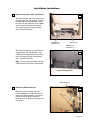
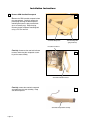
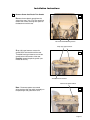
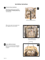
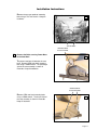
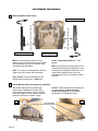
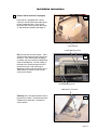
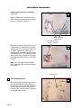
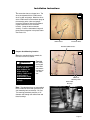
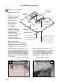
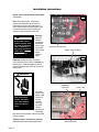
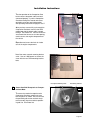
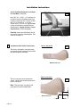
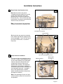
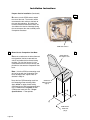
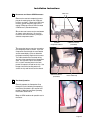
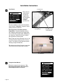
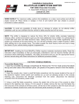
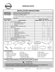
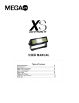
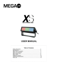
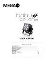
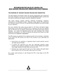
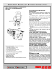
Installation Instructions
Pre-Installation notes, precautions and Instructions
Windstar front passenger power seats must be
retrofitted with manual slide tracks prior to installation of the Braun Companion Seat. Several Ford
parts must be ordered to complete the conversion
(see list below).
Ford Parts List
Item
1
1
Description
Passenger Side Slide Track
Ford Part No.
61705
2
Driver Side Slide Track
61704
3
Passenger Side Seat Guard
62186
4
Driver Side Seat Guard
62187
The Ford part numbers are base numbers. Use
your vehicle’s VIN and the base numbers to order
the correct parts from Ford.
Note: If the vehicle is equipped with a center
console between the driver and passenger seat it
must be removed to allow room for the Companion
Seat base. The console and all features contained
within the console will be removed and not utilized
at this location (example - VCR, entertainment
system or storage compartment).
Disable Vehicle SRS (Supplemental Restraint System)
WARNING
To avoid accidental
deployment and
possible personal
injury, the backup
power supply must be
depleted before
repairing or replacing
any front or side air
bag supplemental
restraint system (SRS)
components and
before servicing,
replacing, adjusting or
striking components
near the front or side
air bag sensors, such
as doors, instrument
panel, console door
latches, strikers, seats
and hood latched.
Before beginning installation
procedures, review the following
precautions and recommendations from Ford Motor Company
regarding a front passenger seat
equipped with a side air bag.
The Ford Windstar can have a
passenger seat equipped with or
without a side air bag deployment
unit. When installing the Companion Seat in a vehicle with a passenger seat side air bag, follow the
procedures in the Ford Windstar
Service Manual to disable the SRS.
An abbreviated list of these Ford
procedures is listed below. Reference the Ford Windstar Service
Manual for a detailed listing of
precautions and procedures for the
deactivation and reactivation of the
SRS.
When the OEM seat assembly is
Note: The passenger seat
side air bag sensors are
located at the base of the Bpillar.
removed from the OEM seat base,
the following steps must be taken to
assure the OEM SRS is fully restored and operational as designed,
tested and manufactured.
WARNING
Never probe connectors on the air bag
module. Doing so can
result in air bag
deployment, which
can result in personal
injury.
WARNING
Do not disconnect the
wire connector at the
side air bag module.
This is a permanent
connection. Doing so
may result in accidental air bag deployment,
which may result in
person injury.
To deplete the backup power supply energy, disconnect the battery ground cable and wait at least
one minute. Be sure to disconnect auxiliary batteries and power supplies (if equipped).
After the backup power supply has been depleted, continue with the installation of the Companion
Seat.
Page 12
Installation Instructions
2
Remove Passenger’s Seat and Pedestal
2a
Two floor mounted studs secure the rear of
the passenger seat and pedestal. Remove
the stud caps to access the washer head
hex nuts (the caps snap off). Use a 18MM
wrench to remove the washer head hex
nuts securing the rear of the passenger
seat. Keep the OEM nuts.
OEM Washer
Head Nuts (2)
Stud Caps (2)
OEM Washer
Head Bolts (2)
Two washer head bolts secure the front of
2b
the passenger seat and pedestal. Use a
13MM wrench to remove the washer head
bolts securing the front of the passenger
seat. Keep the OEM bolts.
Note: Do not remove passenger seat until
OEM connectors have been disconnected.
Front of Passenger Seat
OEM Connectors
3
Disconnect OEM Connectors
3
Carefully tip the passenger seat and
pedestal toward the rear of the vehicle to
expose the OEM connectors. Disconnect
the yellow and the green connectors.
Remove the seat / pedestal assembly from
the vehicle.
Page 13
Installation Instructions
4
Remove OEM Seat Belt Receptacle
4a
Remove the OEM seat belt receptacle from
the seat pedestal. Carefully remove the
plastic plug covering the belt receptacle
mounting bolt (turn the plug counterclockwise to remove plug). Keep the plug.
Remove the belt receptacle mounting bolt
using a T50 Torx wrench.
Seat Belt Receptacle
Torx Mounting Bolt
(plug removed)
Disconnect Harness
Carefully disconnect the seat belt indicator
4b
harness connecting the receptacle assembly to the seat assembly.
Seat Belt Indicator Harness
Carefully remove the seat belt receptacle
4c
assembly from the seat assembly. Keep
seat belt receptacle.
Seat Belt Receptacle Assembly
Page 14
Installation Instructions
5
Remove Power Seat Plastic Trim Guards
5a
Remove the two plastic guards from the
sides of the seat. Use a T30 Torx wench to
remove the screws securing each panel to
the bottom rear of the seat.
Torx Seat Guard Mounting Screws
Snap (clip) type fasteners
Snap (clip) type fasteners secure the
guards to the side and front of the seat.
Threaded insert type fasteners secure the
guards to the front corners of the seat.
Carefully remove the plastic guards (see
Photos 5b and 5c).
5b
Threaded Insert Fastener
Power Seat Control Switch
Note: Disconnect power seat control
wiring harness from the switch assembly on
the passenger side guard of the seat.
5c
Page 15
Installation Instructions
6
Disconnect Power Seat Motors
6a
Disconnect the power harness to each of
the three power seat motors mounted on
the seat pedestal. The harnesses have red
connector plugs.
Disconnect three Motor Harness
Cable tie the motor harness together and
to the bottom of the seat as shown.
6b
Power Seat Motor Harness
Cable Tied to Seat Bottom
T40 Torx Bolts
7
Remove OEM Seat Pedestal
7a
Remove the two front pedestal mounting
bolts using a T40 Torx wrench. Keep the
hardware.
Page 16
Front
Installation Instructions
Remove the two rear pedestal mounting
bolts using a T40 Torx wrench. Keep the
hardware.
Rear
7b
T40 Torx Bolts
OEM Seat Back
Securement Bolt
8
Remove the Bolts securing Power Base
to the Seat Back
8a
The power seat base is bolted to the seat
back. Remove OEM seat back mounting
bolt using a 15MM wrench. The passenger
side of the seat assembly is shown in
Photo 8a. Keep the hardware.
OEM Seat Back
Securement Bolts
Remove OEM seat back mounting bolts
using a 15MM wrench. The drivers side of
the seat assembly is shown in Photo 8b.
Keep all hardware.
8b
Page 17
Installation Instructions
9
Mount the Manual Slide Tracks
Top View of Part # 61705
Seat back (driver side) bolts here.
Seat back (passenger side) bolt here.
Top View of Part # 61704
View of Installed
Manual Slide Tracks
Mount the manual slide tracks to the seat
bottom using a T40 wrench to secure the OEM
bolts that previously secured the power slide
assembly to the seat bottom.
Note: To access the mounting holes, slide the
lower track of the manual slide assemblies.
Apply Loctite® or other thread locking com-
curely. Torque Specifications: 17 foot
pounds.
Note: Be sure to set the slide position on the
manual slide tracks before mounting the seat
assembly to the Companion Seat base. The
“front-to-back” position of the seat is not
adjustable after the seat assembly has been
mounted.
pound to the mounting bolts. Tighten se-
10
Secure Manual Slide Seat assembly to Seat Back
Secure the seat back to the manual slide
tracks using a 15MM wrench on the OEM
bolts retained from Step 8. There is one bolt
on the passenger side and two bolts securing
the drivers side of the seat back. Apply
Loctite® or other thread locking compound to
the mounting bolts. Tighten securely.
Torque Specifications: 30 foot pounds
(passenger), 33 foot pounds (driver).
10a
OEM Seat Back
Securement Bolts
Page 18
10b
Installation Instructions
11
Remove Center Console (if equipped)
11a
If the vehicle is equipped with a center
console it must be removed to allow space
for the Companion Seat. If the vehicle
does not have a center console, omit Step
11 and continue installation with Step 12.
Center Console
Console Mounting Screws
Open the top of the center console. There
11b
are two screws inside the box that must be
removed. If the console does not appear
as shown, you must remove the obstruction
(refer to Ford Manual). Pull the handle at
the front of the console and pull the VCR
out of the console. After removing all
obstructions from inside the console, use a
7MM wrench to remove the four screws
securing the console.
Console Mounting Screws
OEM Harness Connectors
Carefully tilt the console toward the rear of
the vehicle as shown. Disconnect the three
OEM harness connectors. Remove the
center console.
11c
Page 19
Installation Instructions
Remove Center Console (if equipped)
(Continued)
11d
Use an 11MM wrench to remove the four
bolts securing the center console mounting
brackets. Remove the brackets.
Console Mounting
Bracket Bolts
Tape, Wire Tie & Tuck
harness as shown
Use electrical tape to cover the ends of the
Rear
11e
Front
OEM connectors. Wire tie the connectors
together and tuck them into the carpet void
as shown. Replace the front bracket’s
mounting bolts and tighten securely to plug
the mounting holes. The connectors, bolts
and the front carpet void will be covered by
the Companion Seat base once it has been
installed.
Note: The rear carpet void will be fitted
with a cover plate after the power cable has
been routed.
OEM Harness
12
Extend OEM Harnesses
The OEM seat power harness (green plug)
and seat mounted side air bag harness
(yellow plug) must be extended. Carefully
cut the OEM wiring harness two inches
from the green and yellow plugs. Strip 3/8"
of insulation from all wires.
Page 20
12a
Installation Instructions
The extension wires are shown here. The
12b
wires correspond with the OEM harness
wires in color and gauge. Match the wires
of the OEM harness and connector plugs to
the extension wires (color and gauge).
Insert the OEM wires into the corresponding butt connectors of the extension
harness. Crimp the butt connectors
securely. Place the extended air bag and
power harness together in the plastic loom.
See Photo 13a.
OEM Harness
Extension Wires
Extended OEM Harness
13
Prepare Seat Mounting Location
13a
Route the extended harness toward the
rear of the vehicle as shown.
WARNING
Check for obstructions
such as gas lines,
wires, exhaust, ect.
before drilling or
cutting. Failure to do
so may result in
serious bodily injury
and/or property
damage.
Carefully
drill (ream)
out the two
front OEM
seat mounting holes to
1/2" diameter.
OEM Seat
Mounting Holes
Below Floor
Bushings
Note: Threaded bushings are spot welded
to the underside of the floor (previously for
seat mounting bolt securement). Be sure
The reaming procedure produces a 1/2"
diameter hole though the vehicle floor and
these bushings.
13b
Page 21
Installation Instructions
14
Mount Companion Seat Base
7/16"-20 x 1-1/2"
Threaded
Mounting Studs
Carefully position the seat
base.
OEM Washer
Head Nuts
Two floor mounting cross
members are located
on the bottom of
the Companion Seat
base. One 1/2"
diameter mounting
hole is provided at
the rear of each
cross member.
Carefully position the
OEM Seat
Mounting Holes
(Drilled out)
OEM Rear
seat base by inserting the
Mounting Studs
two threaded studs in the
two OEM front seat
Reinforcement Plate
mounting holes and aligning
7/16" Flat Washer
the two 1/2" diameter
Companion Seat base
7/16" Lock Washer
mounting holes with the
OEM seat rear mounting studs.
7/16"-20 Hex Nut
Note: Route the wiring
harness out the corner of the seat base
(between the driver’s seat and Companion
Seat base) such that the harness is not
damaged when positioning the seat base.
Above Floor Mounting Hardware: Secure
the two OEM rear mounting studs using the
two OEM washer head nuts. Apply Loctite® or
other thread locking compound to the mounting studs. Use an 18MM wrench to tighten
the bolts securely. Torque Specifications:
41 foot pounds.
Above Floor Mounting Hardware
14a
Page 22
Reinforcement Plate
7/16" Flat Washer
7/16" Lock Washer
7/16"-20 Hex Nut
Below Floor Mounting Hardware: Place
one reinforcement plate, one 7/16" flat washer,
one 7/16" lock washer and one 7/16"-20 hex
nut on each of the Companion Seat front
mounting studs. Tighten Securely. Torque
Specifications: 50-55 foot pounds.
Below Floor Mounting Hardware
14b
Installation Instructions
15
Route, Secure and Connect Power Cable
15a
Route the Companion Seat power harness
as shown. Route the harness through one
of the voids in the OEM carpet to the carpet
seam located between the driver and rear
passenger seat. The harness is routed
around the rear of the drivers seat as
shown. Secure the power cable using the
plastic cable clips and self tapping screws.
Reposition the carpet seam to conceal the
power cable.
Void in Carpet
Plastic Cable Clip
with Self Tap Screw
Seam in Carpet with
Power Harness
Remove the driver’s side plastic sill plate.
15b
The sill plate is secured with snap (clip)
fasteners. Route the power cable under
the sill plate toward the fire wall. Reposition and snap in the sill plate.
Door Sill Plate
Rubber Grommet (Boot)
Locate the rubber grommet (boot) located
in the vehicle floorboard that the transmission shifter cable routes though to the
engine compartment. Temporarily pull the
insulated foam mat up from the floor to
access the grommet. Carefully cut a hole
(slit) in the rubber boot for power harness
access.
15c
Page 23
Installation Instructions
Route, Secure and Connect Power Cable
(Continued)
15d
Open the vehicle hood. Temporarily
remove the midsection of the fresh air
intake duct to access the floor board. A
hose clamp secures the passenger’s side
end of the duct and a over-center type
clamp secures the driver’s side end.
WARNING
Route cable clear of
exhaust system, other
hot areas and moving
parts. Failure to so
may result in serious
bodily injury and/or
property damage.
Carefully
route the
harness
through the
floor board
access hole
(see Photo
15e) into the
engine
compartment.
Midsection of Intake Duct
Rubber Grommet (Boot)
15e
Carefully connect the fuse end of the
wiring harness to the vehicle’s Positive (+)
battery post. Squeeze (depress) and lift
the plastic battery post cover to access the
battery post.
WARNING
Positive (+)
Connection
The Companion Seat
power cable
also has a
Risk of electrical
ground
shock! Use extra
terminal.
care when making
Unscrew
electrical connecthe OEM
tions.
chassis
ground and
secure the
eye terminal of the power cable to the OEM
chassis ground.
15f
Tighten harness connections securely.
Reposition the plastic battery post cover.
Page 24
Power Cable
OEM Ground Stud
Installation Instructions
Test the operation of the Companion Seat
15g
base to ensure the power cable has been
connected properly. Cycle the Companion
Seat base through the extend and retract
operations using the hand held pendant.
See operating instructions on pages 6 and 7.
After you have successfully cycle tested the
Companion Seat base, return to the OEM
rubber boot that the power cable is routed
through. See Photo 15e. Caulk or silicon the
area around the harness to seal the opening
used to access the engine compartment of
the vehicle.
Reposition and secure the fresh air intake
duct in the engine compartment.
Install the center console mounting bracket
15h
cover. Use an 11MM wrench to secure the
cover with the rear OEM mounting bracket
bolts.
Receptacle Mounting Hole
16
Secure Seat Belt Receptacle to Companion Seat Base
Positioning Tab Slot
16a
To secure the seat belt receptacle to the
Companion Seat base, position the seat
belt receptacle as shown. Be sure to insert
the positioning tab on the seat belt receptacle assembly into the seat base positioning tab slot. See Photo 16a.
Page 25
Installation Instructions
Secure Seat Belt Receptacle to Companion Seat Base (Continued)
16b
Insert the 7/16" - UNF x 1-1/4" bolt into the
receptacle and the Companion Seat base
receptacle mounting hole. Secure the bolt
with a 7/16" flat washer, a 7/16" lock
washer and a 7/16" hex nut. Apply loctite®
or other thread-locking compound to the
mounting bolt. Tighten securely. Torque
Specifications: 50-55 foot pounds.
Carefully reinsert the OEM plastic plug to
conceal the receptacle mounting bolt. See
Photo 4a on page 14.
17
Trim Manual Slide Plastic Seat Guards
Rotating Base
Seat Belt Receptacle
Driver’s Side Guard
17a
The driver’s side plastic seat guard must
be trimmed to allow clearance for the OEM
seat belt receptacle assembly.
Before Modification
Driver’s Side Guard
Trim the seat guard to the dimensions
17b
shown. Remove the dashed portion of the
plastic seat guard.
Note: The passenger side plastic seat
guard does not require modification.
1-1/4"
After Modification
2"
Page 26
Installation Instructions
18
Mount Plastic Seat Guards to Seat
18a
Reposition the plastic seat guards.
Threaded insert type fasteners secure the
guards at the front corner of the seat,
(position these first and work toward the
back of the seat). There are two snap (clip)
type fasteners securing the guard along the
side of the seat, secure them.
Note: Only the manual slide seat guards
should be used with the Companion Seat.
Snap (clip) type fasteners
Threaded Insert Fastener
Plastic Guards
At this point the seat guard rear mounting
18b
holes should align with the mounting holes
on the seat bottom. Use a T30 Torx wench
to install the OEM screws. As shown in
Photo 18b.
19
Prepare Seat for Installation
The manual slides have mounting studs at
each end. Using the slide adjustment lever
on each slide assembly or the slide adjustment bar, adjust the stud position to be
straight across from the studs on the
opposite slide assembly. Also adjust the
stud position “front-to-back” to determine
the location of your seat after mounting it to
the Companion Seat base. If equipped
with a slide adjustment bar, remove it
before mounting (squeeze the legs of the
bar together to remove).
Torx Seat Guard Mounting Screws
Mounting Stud (4)
Manual Slide
Assembly (2)
19a
Note: After mounting the seat, the “frontto-back” position (slide) of the seat will not
be adjustable.
Page 27
Installation Instructions
Prepare Seat for Installation (Continued)
19b
Be sure to run the OEM harness toward
the rear of the seat. The harness will be
reconnected to the vehicle at the back of
the seat after mounting. By routing the
harness toward the back of the seat it will
also reduce the chance of damage during
the securement of the seat assembly to the
Companion Seat base.
OEM Seat Harness
20
20
Mount Seat to Companion Seat Base
OEM (original)
Passenger's Seat
Rotate the seat base to the locked forwardfacing position (the base retracted into
vehicle and rotated to the forward facing
position). Be sure the harness is clear
(routed toward the rear of the vehicle) and
position the seat onto the Companion Seat
base.
Note: If the four OEM seat mounting studs
do not line up with the Companion Seat
base mounting holes, adjust slides as
detailed in Step 19.
Insert the four OEM mounting studs into
the Companion Seat mounting holes.
Apply loctite® or other thread locking
compound to the OEM seat mounting bolts.
Use a 13MM wrench to tighten the four
OEM washer head lock nuts. Torque
Specifications: 17 foot pounds.
OEM Seat
Mounting Studs
(Qty. 4)
OEM Washer
Head Nuts
(Qty 4)
Page 28
Installation Instructions
21
Reconnect and Secure OEM Harnesses
Cable Ties
Connect the seat belt receptacle harness
21a
plug to the mating plug on the OEM seat
harness as shown. Connect the OEM seat
harness (yellow and green plugs) to the
mating OEM plugs from the floor mounted
OEM harness (extended harness).
Secure the seat harness to the seat bottom
as shown using cable ties. Be sure the
harnesses are secured loosely enough to
eliminate component strain.
Seat Belt
Receptacle Harness
OEM Seat Harness
(Extended)
The extension harness must be secured to
21b
the Companion Seat as shown. Cycle the
Companion Seat through the seat rotation
and the stow/deploy cycles to determine
the proper mounting length for the harness.
The cable should not be strained during
any part of the operation of the Companion
Seat. Use a plastic clip for securement.
Drill a 13/64" mounting hole in the Companion Seat plastic shroud for the clip. Use
the pop rivet with a backing washer to
secure the clip and harness to the shroud.
OEM Seat Harness
(Extended)
22
Test Seat Operation
Plastic Cable Clip
22
Carefully operate the Companion Seat
through all cycles following the operating
instructions contained in this manual and
posted on Warnings and Seat Operating
Instructions decal 22616.
Keep all OEM hardware for possible use in
the future.
Page 29
Installation Instructions
23
Decal #21419
Post Decals
WARNING
Affix decals as specified. Failure to do so
may result in serious
bodily injury and/or
property damage.
Post (affix) the
23a
safety instructions decals
supplied with
the Companion
Seat at the
locations
specified here.
The decals must be visible to the Companion
Seat occupant. Important! Prepare the decal
posting surfaces as detailed.
Decal Application Procedure (Surface
Passenger's Door
Front Door Post
Decal #21418
Preparation): Clean decal posting surfaces
with isopropyl alcohol before decal application.
Use a clean cloth or paper towels. Do not use
oily shop rags. Wipe surface free of residue
with dry portion of cleaning cloth.
23b
Post Extend and Recline Warning Decal 21418
and Head Clearance Warning Decal 21419 as
shown. Post decals on front door post (plastic
molding) at edge of windshield.
Post Warnings and Seat Operating Instructions
Decal 22616 on the vehicle dash as shown.
Decal #22616
24
Companion Seat Manual:
Provide this manual to the consumer. The
manual must be stored in the Companion
Seat-equipped vehicle at all times.
Page 30
WARNING
Companion Seat
owner's manual must
be stored in seatequipped vehicle at all
times. Failure to do so
may result in serious
bodily injury and/or
property damage.