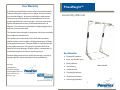
1
Your Warranty If a product purchased from Pneumex does not operate properly, Pneumex will repair or replace it at no charge, for up to one year from the date shipped. In the course of repair or replacement, Pneumex may send you written recommendations on how to prevent a problem from occurring again. Pneumex reserves the right to withdraw this warranty if recommendations are not followed. The customer is responsible for freight charges both to and from Pneumex in all cases. PneuWeight ™ PneuWeight™ Assembly Manual This warranty does not apply to compressors which are covered by the compressor manufacturers. This warranty is exclusive and is in lieu of all other warranties whether written, oral or implied, including the warranty of fitness for any particular purpose. Pneumex liability is in all cases limited to the replacement price of its product. Pneumex shall not be liable for any other damages, whether indirect, consequential, or incidental arising from the sale or use of its products. Pneumex sales personnel may modify this warranty, but only by signing a specific written description of any modifications. Orthopedic patients Knee, hip & ankle injury Pneumex 2605 Boyer Ave Sandpoint, ID 83864 [email protected] www.pneumex.com 800‐447‐5792 Key Benefits Back problems Patent 5181904 Gait training Cardiovascular Overweight patients Pneumex Equipment Respiratory ailments PneuThera Treatment Protocols 28 Neurological patients 1 Distributed by Pneumex, Inc. Pneumex, PneuGait Foot Strap, PneuMAP, PneuBack Chair, PneuWeight and PneuVest are trademarks of Pneumex, Inc. Maintenance Cleaning Use a soft cloth rinsed in warm water to clean the exterior surfaces. Disinfecting All rights reserved Use procedures established for your facility. The vest can be washed with a mixture of water and disinfectant such as Lysol or equivalent. Do not use bleach on the vest or the color will fade. Schedule Service Visit our web site at No scheduled service is required. For service, call Pneumex: USA & Canada: 800‐447‐5792 International: 208‐265‐4105 Copyright 2003 Pneumex www.Pneumex.com Preventive Maintenance Pneumex, Inc. 2605 North Boyer Ave. Sandpoint, ID 83864 Phone 208‐265‐4105 Fax 208‐265‐9651 E‐mail [email protected] Rev 014 Routinely check the air hose, air fittings, and compressor for leaks. Check the unweighting bar and cable for loose wires or fraying. Air Compressor Drain the air compressor at least once a week. For compressor maintenance and service information, refer to the manual supplied by the compressor manufacturer. Revised Feb 26, 2014 Genuine Pneumex Equipment 2 27 Specifications Contents Weight Model Shipping Wt. Preface ............................................................................. 4 Single 135 lb (61 kg) 145 lb (66 kg Using the PneuWeight ........................................................... 5 Double 170 lb (77 kg) 180 lb (82 kg) Indications for Use .................................................................. 6 The following specifications apply to all models. Unweighting capacity 0-300 lb (136.36 kg) Components Single ................................................................ 7 Components Double .............................................................. 8 Unpacking .............................................................................. 9 Assembly .............................................................................. 11 Operating Modes: Exercise 0‐30 in. (0‐76 cm) vertical motion Balance Floor space (w x d) Pneumatic stop limited down motion Single and Double 48 in. x 48 in. (121 cm x 121 cm) Control Panel ....................................................................... 16 Height OD. Adjustable 7 ft.11 in. to 8 ft. 8 in. Attaching the Air Compressor .............................................. 17 Safety Requirements ........................................................... 18 Air hose OD./ID. (2.4 m to 2.64 m) 0.25/0/17 Compressor air fitting Compressor power requirements ¼ MPT Refer to compressor manual supplied by compressor manufacturer. Bases .................................................................................... 11 Uprights ............................................................................... 12 Routing Air ........................................................................... 12 Headers ................................................................................ 14 Instructions for Use .............................................................. 19 Drop Stop ........................................................................ 19 Control Panel .................................................................. 20 PneuVest .............................................................................. 22 Attaching the Vest To the Cable Assembly .......................... 22 Correcting Vest Problems .................................................... 23 We recommend a weekly inspection of cables. All Cable Assem‐ blies should be replace at least every six months. Failure to do so may result in failure of cable and injury. Troubleshooting ................................................................... 24 Replacing the Cable Assembly ............................................. 25 Specifications ....................................................................... 26 Maintenance ........................................................................ 27 26 3 Preface Replacing the Cable Assembly This manual contains the operating instructions and service require‐ ments for the PneuWeight Unweighting System. The manual is Replace the cable assembly if it appears frayed or worn. designed for use by clinical staff and it is expected that the clinicians 1. Remove the control panel. will instruct their patients and clients in the proper use of the system 2. Pull the cotter pin and the clevis pin from the top of the pneumatic cylinder. Cable will fall as soon as you pull the clevis pin. Use caution not to drop any parts into post. and its accessories. The PneuWeight systems are intended to be used as unweighting or offloading devices not as a hoist. Please read the manual carefully, noting the Safety Requirements in Ap‐ pendix A, before using the PneuWeight Unweighting System. Liability Notice Failure to follow the conditions set forth below shall absolve Pneumex, Inc. from any responsibility for the safety, reliability, and performance of this equipment. Each operator must read the operator manual in full before using the product for the first time. Each independent user must be instructed in the proper use of the system and its accessories. The electrical wiring within the system's settings, and the electrical installation of the compressor must comply with the applicable local or provincial requirements. The equipment must be used in accordance with the instructions for use. It is suggested that oper‐ ators of PneuWeight Stations receive approved training and certifi‐ cation from Pneumex, Inc. or their designee before operating the equipment. Please call Pneumex at 800‐447‐5792 to find out more about our training and certification programs. 4 3. Remove the cable by pulling it out from the top of the up‐ right. 4. Install the new cable down from the top of the upright. 5. Reinstall the clevis pin and the cotter pin. 6. Replace the control panel. We recommend a weekly inspection of cables. All Cable Assem‐ blies should be replace at least every six months. Failure to do so may result in failure of cable and injury. 25 Troubleshooting Problem System will not unweight Using the PneuWeight™ Possible Cause System Leak Solution Check for leaks. Re‐ place as necessary Compressor not set to correct psi Set compressor to 100 psi Kinked hose Check hoses for kinks System unweights only partway Subject weighs more than 300 lb. (91 kg) Increase the compres‐ sor setting to 120 psi. The maximum lift is Installed new control panel, but system still leaks Fittings are leaking Reseat or replace the fittings In Exercise mode, cable assembly will not retract Air compressor dis‐ connected or leaking Compressor not set to correct psi Check compressor set‐ ting Installed new control Compressor not set to panel, but system does correct psi not work Check compressor set‐ ting Hoses not connected, kinked or connected incorrectly 24 Check connections and air hose Check hoses inside control panel. Be sure they are connected securely to the proper fitting The PneuWeight™ Unweighting system uses pneumatic power provided by a small compressor and the PneuVest™ to support the patient. The PneuWeight’s™ unweighting capacity of 0 to 300 lb. allows the patient to perform low‐impact kinetic exercises in an upright, functional position. Activities such as walking, running, stair climbing, jumping and balance may all be performed safely while unweighted. If a patient loses their balance or starts to fall the PneuWeight™ systems will support the patient’s entire body weight. The Drop Stop is a mechanical safety stop which can be used in con‐ junction with the pneumatic safety. The center of the Unweighting system is the PneuVest™. This Unweighting harness fits the patient like a snug vest with a strap positioned under the buttocks. The vest allows the patient to exercise in an upright, controlled and safe position. It effectively grips the body to support all or part of the patients weight. You MUST bolt Double systems to the floor using the holes in the base straps. . Use the pre‐drilled holes in the base straps. You will need four 3/8” bolts of appropriate type for your floor — concrete, wood, composite, etc. We recommend you contact your building contractor for correct bolts. We recommend a weekly inspection of cables. All Cable Assemblies should be replaced at least every six months. Failure to do so may result in failure of cable and injury. 5 Indications for use Acute and chronic backs Before unweighting anyone, be sure the waist belt is snug and that the safety snaps (carabineers) are closed completely. Back pain Ruptured disc ‐ herniated / bulged Chronic headache / upper thoracic tightness Post surgical Osteoporosis After unweighting, ask the subject if the vest feels uncomfortable. Be sure that the vest is not wedged into the underarms and that it does not restrict breathing. Be sure that the leg straps are not tight enough to restrict circulation in the legs. Readjust the vest as nec‐ essary. Knee, hip & ankle injury Correcting Vest Problems Orthopedic patients Overweight patients If the vest rides up under the arms, re‐weight and pull the vest down. Have the person tighten the abdominal muscles, then re‐ tighten the waist straps and leg straps. The Jo Straps can help to keep the vest in place. See PneuVest manual for instructions. Respiratory ailments If the chest strap is too tight during exercise, loosen it. Neurological patients If the leg cuffs ride up, re‐weight if necessary and replace the cuff centering the front leg strap on the thigh. Some people like the cuff higher up on the thigh, but for most patients the cuff is more comfortable just above the knee. Pull the strap around cuff snugly. If the leg straps are too tight, or seem to pinch, try changing the position higher or lower on the thigh. Cardiovascular Assist in lifting wheelchair patients Contraindications Tumors on the spine Respiratory conditions which are exacerbated by pressure on the rib cage. This can sometimes be compensated for by taking more weight through the legs or by using a thoracic vest. PneuVest Vectors with IT Strap 6 23 PneuVest Components A correctly fitted PneuVest vest is the key to successful un‐ weighting. When choosing a vest, select one that corresponds to the user’s waist size, The vests are color‐coded. Single PneuWeight See the PneuVest instruction booklet Attaching the Vest to the Cable Assembly 1. Each shoulder strap on the vest has a D‐ring that attaches to the cable assembly. Adjust the upright posture of the person being unweighted by moving the D‐ring back or forth on the straps. For example, to flex the person, slide the D‐ring backward. To extend the person, slide the D‐ring forward. Box #1 ‐ Two base supports: package includes instructions, installa‐ tion hardware, air hose, and one PneuVest Box #2 ‐ Two upright posts , cable assembly and control panel Box #3 ‐ One header beam assembly Box #4 ‐ Compressor (if ordered) Cable keepers Header Gusset 2. Attach the D‐rings to the safety snaps on the cable assembly. 3. Use the control panel to unweight. Attaching a wheelchair user to the Cable Assembly Cable Assembly You may need to use extension chains to connect wheelchair users to the cable assembly. 1. Place the wheelchair under the cable assembly (for treadmills, you may need to use a ramp to place the person under the bar). 2. Pull the cable assembly down and connect the to the extension chains.. Drop Stop Control panel Upright Base 3. Attach the D‐rings on the vest securely to the clips on the exten‐ sion. Unweight the person from the chair and remove the chair. Adjust the extension as needed. 22 Base Straps 7 Balance Mode Double PneuWeight DPW Box #1 ‐ Two base supports: package includes instructions, installa‐ tion hardware, air hose and two PneuVests Box #2 ‐ Two upright posts, cable assembly and control panels Box #3 ‐ One header beam assembly Box #4 ‐ Compressor (if ordered) Cable keepers Header Balance mode lets the user perform exercises involving less vertical movement, such as walking, running, or balance activities, without fear of falling. The system supports the entire body weight during loss of balance, allowing a fall of no more than three to six inches. Balance mode frees the assistant to use both hands while assisting the user. The majority of treadmill activities will be done in the bal‐ ance mode. The exercise mode is used for adjusting the amount of Unweighting when performing activities that require more vertical oscillation than balance mode allows, e.g. retraining sit to stand or step up/step down activity. You may want to show the patient they cannot fall in the system. To decrease the distance the system will allow a patient to come down: Balance Mode Control panels Cable Assembly Drop Stop More weight can be removed before switching to balance. Patient can stand on their tiptoes or a stool before switching to balance Uprights OFF Base OFF mode releases the air from the system quickly. This mode can be used to re‐weight a person quickly if desired. Base straps 8 21 Exercise Mode Unpacking Exercise mode lets the user perform long vertical movements, such as jumping or stair climbing, with consistent Unweighting over the full range of movement. All Unweighting adjustments are done in Exercise mode. Turn the PneuWeight™ Mode selector switch to exercise mode and using the regulator dial in the desired amount of weight to be un‐ weighted. Note: the usual protocol to deter‐ mine the amount of weight to be removed is “pain‐free” or “pain tolerable”. This will usual‐ ly be around 30% to 50% of body weight. Dual systems have two control panels. The exceptions are: Installation Post surgical‐in many cases will be percent‐ age weight bearing dictated by M.D. Electrical Requirements Neurological or spinal cord injury (SCI)‐ to stabilized or normalized upright state. Quite often this will entail removal of close to 100% of body weight to assist in lift and then adding weight back to patient as desired. Sciatica ‐ quite often quire 70% + of body weight off in early stages. re‐ Exercise Mode 20 Tools required: sharp knife 1. Cut all tape and remove corrugated and plastic wrapping. 2. Remove the operator/service manual, air hose, and vest(s) and store them temporarily in a safe place. 3. The unweighting bar and the air hose are tucked inside the uprights for safety during shipping. The compressor requires an appropriate AC line. Refer to the manu‐ al supplied by the compressor manufacturer for electrical require‐ ments. Ceiling Height Before assembling, determine how high to make the system. The series of holes in the bottom 1/3 of the bases provides 4 height options, progressively changing by 3 inches (7.6 cm). The total height on a dual system can be set to any of the following: 7 ft. 11 in. (2.41m) – using top pivot hole in base 8 ft. 2 in. (2.49 m) – 2nd pivot hole 8 ft. 5 in. (2.57 m) – 3rd pivot hole 8 ft. 8 in. (2.64 m) – bottom pivot hole 9 For installation, the ceiling height should be at least 1 inch (2.5 cm) higher than the final system height. Instructions When determining the desired height consider the following: 1. Turn on the air compressor. Refer to the compressor manual for compressor operating instructions. At minimum height (uprights fully inserted into the base), the system accommodates users up to 6 feet 4 inches (1.93m) tall. If the ceiling is a drop ceiling, can the tiles be removed, the sys‐ tem installed above the suspended ceiling, and the tiles re‐ placed? If it is a sheet rock ceiling, can you cut the sheet rock and frame in the area above for more clearance? Type of use The type of exercise equipment used under the system affects the required height. For example, if you are using a treadmill whose walking surface is 6 inches (15.2 cm) from the floor, you should add 6 inches (15.2 cm) to the frame height. It is recommended the unit be bolted to floor. Use the pre‐ drilled holes in the base straps. You will need four 3/8” bolts of appropriate type for your floor — concrete, wood, composite, etc. We recommend you contact your building contractor for correct bolts. You MUST bolt PneuWeight systems to the floor using the holes in the base straps. 2. WARNING: Ensure that all personnel and equipment are clear of the unit as sudden system pressurization can cause the cable assembly to retract rapidly. 3. Fit the vest correctly to the subject as described in the PneuVest manual and connect the vest securely to the un‐ weighting bar. 4. Select desired weight to be unweighted, 5. Select Exercise or Unweight. and enter desired weight to be removed 6. For activity with up to 30 inches (76.2 cm) vertical motion, leave the select mode knob on Exercise. 7. For activity with less than 6 inches (15.2 cm) vertical motion, set the select mode knob to Balance. This will ensure that the user remains upright. 8. As an extra safety step you can use the Drop Stop which is a mechanical safety stop that can be used in conjunction with the pneumatic safety. Firmly insert fork into upright post, make sure nut is tightened to prevent fork from vibrating loose during exercise. Have patient bend knees or pull downward on cable assembly to check length of drop. If drop is too long move Drop Stop to next lower level. 9. To lower patient, press the Lower button and hold for 2 sec‐ onds. 10. Disconnect the person from the system and remove the vest. 10 19 Safety Requirements Assembly The PneuWeight systems are intended to be used as un‐ weighting or offloading devices not as a hoist. Tools required Do not start the PneuWeight System until you are sure the vest is properly secured. Do not operate this equipment in the presence of flammable anesthetic mixtures. To avoid potential safety problems, use parts and accessories that meet specifications given in this manual. The compressor must be on an appropriate electrical circuit. Read the manual supplied by the compressor manufacturer before using the compressor with the PneuWeight System. Before each use, inspect the air tubing for damage, pinched are‐ as, and leaks. Inspect the power receptacle for damage. Do not use if the integrity of these items is questionable. Check all rollers for any wear or groves If customer is walking 3‐5 mph or less unit does not need to bolt to floor; however at 5 mph or more it is recommended the unit be bolted to floor. Use the pre‐drilled holes in the base straps. You MUST bolt double systems to the floor using the holes in the base straps. We recommend a weekly inspection of cables. All Cable Assem‐ blies should be replace at least every six months. Failure to do so may result in failure of cable and injury. 7/32 in. x 6 in. “T” handle hex key (provided) for majority of as‐ sembly 7/32 in. short arm hex key (provided) use on base straps Air hose (provided) Single 20’ ‐ Double 40’ “T” air fittings (provided) Single 1 fitting ‐ Double 2 fittings Bases 1. Place the bases facing the same direction, with the open face closest to the wall, about 41 in. (1 m) apart (the length of the base straps) 2. Attach the base straps between base as shown in Fig. 1 using 4 each 3/8 in. x 1/2 in. bolts (provided) Uprights go here Base straps Holes to attach unit to floor 18 11 Fig. 1 Uprights Attaching the Air Compressor 1. Start 2 each 3/8 in. x 1/2 in. pivot bolts into the threaded holes at the top of the base. See Fig . 2 2. Rest uprights on base, with the control panel facing down, aligning the pivot bolt with correct height adjustment hole (see page 16, ceiling height section) See Fig. 2. 3. Tighten the pivot bolts on bases into pivot holes in uprights Start pivot bolts here Read the instructions supplied by the manufacturer of the air compressor before using the compressor. Single PneuWeight – Push one end of air hose supplied with the system into fitting on air compressor, route hose to your PneuWeight (use a route that is out of the way of foot traffic) . You can cut hose to desired length and push hose into air fitting on your PneuWeight. Use “T” fitting supplied with unit to route air from your Single unit to other pneumatic equipment or to a second up‐ right if you have a Double PneuWeight. A Double PneuWeight is supplied with two “T” fittings so if needed you can route air to other equipment. Turn on the air compressor and open valve. Refer to the compressor manual for operating instructions. Check for air leaks (hissing) and tighten fittings if necessary. Any loosening caused by shipping is noticeable during initial operation. Attach base straps here Fig. 2 If you find a hole in any point of the air line, you must replace that line. Tape will not hold during operation of the high pres‐ sure system. Repeat steps 1‐3 for each base and upright Routing the Air Hose The air hose to the compressor is from the bottom of the upright post (call Pneumex for instructions when routing air hose through a hanging ceiling). 12 17 8. Remove bolts 3/8 x 1/2 at bottom of uprights (four each upright) Upright Bolts Base 9. Raise the upright and header as‐ sembly to a vertical position (using a second person is recommended for safety.) 10.Insert the four (3/8 x 1/2) bolts in the base (while still holding unit vertical). Repeat for each upright and tighten securely. Unit will now stay upright. 11.Your Unit has an Analog Control Panel it is shipped connected and ready to use. Gauge/Control Function Unweighting pressure gauge Indicates the number of pounds/kilograms the sys‐ tem is Unweighting Unweighting reg‐ Gradually increases (+) or ulator knob decreases (‐) the amount of Unweighting lift) Mode selector switch 16 Provides choices of Exer‐ cise, Balance, or Off (OFF‐ EX‐BAL) Remove Black Hose Before Use 1. Remove the plastic wrap from base of upright and pull air fit‐ ting out the bottom (should have short black hose attached). 2. Remove one nut from the air fitting, then insert black hose and fitting through air inlet hole in upright top hole. See Fig. 3 Note: Black hose not shown in Fig. 3 Air inlet Air fitting (Inlet hole) Air hose (inside post) Post end Control panel power plug Fig. 3 3. Slip nut (removed in step 2) over black hose and while pulling firmly on black hose tighten nut on air fitting. 4. Black hose can now be removed by compressing lock ring on air fitting. See Fig. 4 Black hose Pull hose out of fitting Compression ring Fig. 4 Bulkhead air fitting Push down on compression ring 13 Headers 1. Unhook and pull the cable assembly out through the top of each upright. 2. Remove the 3/8 in. x 3/4 in. bolt and washer from the top of each upright. 3. Position the header assembly on two chairs align the up‐ rights. 5. Remove the 3/8 x 3/4 in. bolts and washers from the gussets on the header. 6. Pass the cable assembly (remove the snap hooks from eye bolts) and cable through the hole in the header beam; through the cable keepers (pull out keepers and replace over cable), over the rollers, and back down through the center hole. See Fig. 5 7. Slide the header assembly over the ends of the uprights, lining up the bolt holes in the top and on the gussets. 8. Secure the gussets to the uprights by inserting the 3/8 in. x ¾ in. button head bolts and washers (use caution not to drop bolt washer inside of upright during this step). 9. Insert the 3/8 in. x ¾ in. button head bolts and washers in the top of the header beam (stabilization bolt). 10. Tighten all bolts securely. Tighten stabilization bolts first then tighten gusset bolts (this keeps unit from binding). 11. For proper stability, make sure the stabilization bolt is se‐ curely installed in the header beam. Header Cable routing Rollers Cable keepers Uprights Control Panel Gusset Bases Gusset Cable assembly Drop Stop Double systems – pass each additional cable assembly and cable through the corresponding holes in the header beam, through the cable keeper, over the rollers, and back down through the appropriate hole. Stabiliza- Fig. 5 14 Upright 15