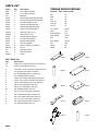
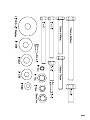
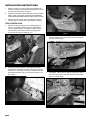
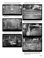
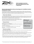
1
#9228
Installation Instructions
2” Body Lift
1998-2003 S-Series Blazer, 2/4wd, ZR-2
Read and understand all instructions and warnings prior
to installation of system and operation of vehicle.
SAFETY WARNING
BDS Suspension Co. recommends this system be
installed by a professional technician. In addition to
these instructions, professional knowledge of disassembly/reassembly procedures and post installation
checks must be known.
PRODUCT SAFETY WARNING
Certain BDS Suspension products are intended to
improve off-road performance. Modifying your vehicle
for off-road use may result in the vehicle handling
differently than a factory equipped vehicle. Extreme
care must be used to prevent loss of control or vehicle rollover. Failure to drive your modified vehicle
safely may result in serious injury or death. BDS Suspension Co. does not recommend the combined use
of suspension lifts, body lifts, or other lifting devices.
You should never operate your modified vehicle under
the influence of alcohol or drugs. Always drive your
modified vehicle at reduced speeds to ensure your
ability to control your vehicle under all driving conditions. Always wear your seat belt.
Pre-Installation Notes
1. Special literature required: OE Service Manual
for model/year of vehicle. Refer to manual for
proper disassembly/reassembly procedures of
OE and related components.
2. Adhere to recommendations when replacement
fasteners, retainers and keepers are called out in
the OE manual.
3. Larger rim and tire combinations may increase
leverage on suspension, steering, and related
components. When selecting combinations larger
than OE, consider the additional stress you could
be inducing on the OE and related components.
rev. 11/6/2008
4. Secure and properly block vehicle prior to installation of BDS Suspension components. Always
wear safety glasses when using power tools.
5. BDS Suspension Co. body lifts are designed to
be used on vehicles in good operating condition.
It is not recommended that body lifts be used on
vehicles in poor physical shape. This includes
rusted body mounts, damaged or worn frameto-body mounting brackets, and poor mechanical condition. Perform a visual inspection of the
vehicle before beginning installation.
POST-INSTALLATION WARNINGS
1. Check all fasteners for proper torque. Check to
ensure for adequate clearance between all rotating, mobile, fixed, and heated members. Verify
clearance between exhaust and brake lines, fuel
lines, fuel tank, floor boards and wiring harness.
Check steering gear for clearance. Test and
inspect brake system.
2. Perform steering sweep to ensure front brake
hoses have adequate slack and do not contact
any rotating, mobile or heated members. Inspect
rear brake hoses at full extension for adequate
slack. Failure to perform hose check/replacement
may result in component failure. Longer replacement hoses, if needed can be purchased from a
local parts supplier.
3. Perform head light check and adjustment.
4. Re-torque all fasteners after 100 miles. Always
inspect fasteners and components during routine
servicing.
102 S. Michigan Avenue • Coldwater, MI 49036
517-279-2135 • www.bds-suspension.com
Page 1
Parts List
Part #
QtyDescription
3296
2296
234
01642
01602
01633
01749
01752
01719
400410
400406
01720
01723
01722
01731
01746
099000
241
244
342701
12
4
1
1
1
4
1
1
1
1
1
2
1
1
2
2
6
2
2
1
2" x 3" Body Lift Block
2" x 2" Body Lift Block
Bolt Pack
Ground Strap Relocation Bracket
Ground Strap Relocation Bracket
Fan Shroud Spacer Tube
Rear Bumper Bracket (drv)
Rear Bumper Bracket (pass)
Lower Fan Shroud Support
Fuel Filler Hose 2" x 6"
Vent Hose 3/4" x 6"
Outside Bumper Bracket
Front Oil Filter Bracket
Rear Oil Filter Bracket
Tow Hook Spacer
0.500 x 0.058 x 2.970 Sleeve
Zip Tie
#12 Hose Clamp
#36 Hose Clamp
Loctite
Bolt Pack 234
Torque Specifications
Fastener Max. Torque (ft-lbs)
1/4”
10
5/16”
17
3/8”
30
7/16”-14
50
7/16”-20
55
1/2”-13
75
1/2” U-Bolt
65-80
9/16”
110
9/16” Grade 8
170
9/16” U-Bolt
75-90
5/8”
150
5/8” U-Bolt
85-110
3/4”
270
10mm
30
12mm
55
01602
01722
01633
01723
01642
01720
01719
01731
01749
01746
QtyDescription
12
12
2
1
2
3
4
4
4
2
2
32
4
8
1
2
2
4
Page 2
12mm-1.75 x 140mm bolt class 10.9 clear zinc
7/16" USS flat washer clear zinc
1-3/4"OD x 1/2"ID s 3/16" thk washer clear zinc
1/4"-20 x 3/4" bolt grade 5 clear zinc
1/4"-20 prevailing torque nut clear zinc
1/4" USS flat washer clear zinc
10mm-1.50 x 80mm bolt class 8.8 clear zinc
10mm-1.50 x 70mm bolt class 10.9 clear zinc
12mm-1.75 prevailing torque nut clear zinc
3/8"-16 x 4" bolt grade 5 clear zinc
3/8"-16 x 1" bolt grade 5 clear zinc
3/8" USS flat washer clear zinc
3/8"-16 x 3-1/2" bolt grade 5 clear zinc
3/8"-16 prevailing torque nut clear zinc
#12 x 3/4" sheet metal screw clear zinc
1/2"-13 x 1-1/4" bolt grade 5 clear zinc
1/2"-13 prevailing torque nut clear zinc
1/2" SAE flat washer clear zinc
Page 3
INSTALLATION INSTRUCTIONS
1.
Park the vehicle on a clean, flat surface and block the
wheels for safety. Place automatic transmissions in park
and manual transmissions in neutral.
2.
Remove the negative battery cable first, then the positive
battery cable. If equipped, the Supplemental Restraint
System will be deactivated when the battery is disconnected.
3.
Measure and record the space between the bumpers
and the body for reference during installation of the kit.
Front/Under Hood
4.
Remove the grill by pulling the ten retaining clips free
from the core support. Remove the turn signal lamps
from the signal housings. If equipped, remove the two
wire harness connectors from the running lights and
remove the grill from the vehicle (Fig 1).
FIG. 3
6.
Remove the two bolts mounting each of the outside
bumper brackets to the frame and remove the brackets
from the vehicle (Fig 4).
FIG. 1
5.
Remove the front bumper by removing the four bolts
mounting the bumper to the frame horns (Fig 2) and two
bolts (one on each side) mounting the bumper to the outside bumper brackets (Fig 3). Remove the bumper from
the vehicle.
FIG. 4
7.
If equipped, remove the two bolts mounting each of the
tow hooks in the frame rails and remove the tow hooks
from the vehicle (Fig 5).
FIG. 2
FIG. 5
Page 4
8.
Remove the plastic air scoop (Fig 6) from the core support
by carefully releasing the four plastic push in fasteners.
11. If equipped, remove the AC line from the plastic hose
clip on the upper fan shroud (Fig 9).
FIG. 6
9.
Remove the six bolts and the front skid plate from the
vehicle (Fig 7).
FIG. 9
12. Remove the seven bolts mounting the upper fan shroud
to the core support and lower fan shroud (Fig 10, 11).
Remove the upper fan shroud from the vehicle.
FIG. 7
10. Disconnect the oil filter mounting bracket from the core
support by removing the two shoulder bolts (Fig 8).
FIG. 10
FIG. 8
FIG. 11
13. Pull the lower fan shroud free from the lower retaining
clips and let it rest on the frame rails. Note: A flat head
screw driver may be required to release the lower fan
shroud retaining clips.
Page 5
14. Remove the nut retaining the ground strap at the
passenger’s side firewall and remove the wire from the
stud (Fig 12).
FIG. 12
15. Remove the four screws mounting the air filter housing
cover and remove the cover. Remove the intake hose
from the throttle body and allow the intake hose assembly to rest on the engine during lifting.
17. 4wd only: Remove the two bolts mounting the battery
tray to the core support and remove the battery tray from
the vehicle (Fig 14).
FIG. 14
18. 4wd only: Remove the two sheet metal screws and
bracket mounting the positive battery cable terminal box
to the core support (Fig 15).
16. 4wd only: Remove the battery retaining clamp and remove the battery from the vehicle (Fig 13).
FIG. 15
19. 4wd only: Remove the two bolts mounting the front axle
actuator to the passenger’s side inner fender. The bolts
are accessed from inside the wheel well (Fig 15, 16).
FIG. 13
FIG. 16
Page 6
Under Body/Frame Rails
20. Remove the bolt mounting the ground strap(s) to the
passenger’s side frame rail (Fig 17).
FIG. 17
21. Remove the wire harness from the plastic clip on the
passenger’s side frame rail (Fig 18).
23. Remove the bolt mounting the brake lines to the driver’s
side shock mount (Fig 20).
FIG. 20
24. Remove the brake line from the plastic retaining clip on
the driver’s side frame rail (Fig 21).
FIG. 21
FIG. 18
22. Remove the bolt/clip mounting the oil cooler lines to the
passenger’s side of the engine oil pan (Fig 19). Remove
the lines from the pan.
25. Remove the wire harness from the plastic retaining clip
on the driver’s side frame rail (Fig 22).
FIG. 22
FIG. 19
Page 7
Rear/Rear Bumper
26. Remove the fuel filler cap to access the three screws
mounting the filler neck to the plastic body shroud
(Fig 23). Remove the three screws to allow the filler
neck to fall through the shroud while lifting the bed.
FIG. 25
34. Repeat lift procedure on driver’s side of the vehicle.
FIG. 23
28. Disconnect the main license plate light wire harness
connector at the frame (Fig 24).
Note: 4-door models have two more body mounts than 2-door
models. If installing on 2-door, 2 blocks and bolts will be extra.
35. If necessary, adjust the body so it is square on the frame
and tighten all mounting bolts securely. Use Loctite® on
all mounting hardware.
Rear/Rear Bumper
44. Remove the license plate from the rear bumper.
45. Remove the top plastic cover from the rear bumper by
squeezing the plastic clips and pushing them out of the
holes (Fig 26).
FIG. 24
29. Remove the 4 bolts (or 5 with some hitch options)
mounting each of the rear bumper brackets to the frame.
Remove the bumper from the vehicle.
Lift
30. Do a thorough visual check of all wires, hoses, etc to
ensure that everything has adequate slack for 2” of lift.
FIG. 26
46. Remove the eight bolts and the bumper brackets from
the rear bumper (Fig 27).
31. Loosen but do not remove all of the body mount bolts.
There are five body mounts on each side of the vehicle.
32. Remove the passenger’s side mounting bolts. Using a hydraulic jack and block of wood, slowly lift the passenger’s
side of the cab high enough to place the 2” tall x 3” wide
spacers on the frame body mounts. While lifting, continue
to watch for hoses, wires, etc that may be overextending.
33. Install 12mm x 140mm bolts and 7/16” USS washer in
conjunction with the OE washer and bushings in the
main cab mounts. Install a 12mm x 140mm bolt with
large ½” washer in the front core support mount from the
top down and fasten with the OE bushing, washer, and
nut (Fig 25). Leave all hardware loose at this time.
Page 8
FIG. 27
47. Install the new rear bumper brackets with the OE hardware and four 12mm nuts with four 7/16” USS washers
to replace the welded nuts on the upper OE bracket
mounts. Do not tighten at this time.
47b.The bottom corner of the rear frame horns must be
trimmed to make clearance for the relocated bumper.
Measure from the back edge of the frame 1-5/8" and
mark. Measure up from the bottom of the frame 1-1/2"
and mark. Cut out the marked off square section of the
frame with a saw or cut-off wheel. Paint exposed metal
to prevent rust.
48. Install the bumper on the vehicle by aligning the original mounting holes with the corresponding holes in the
new brackets. Use a 1/2" x 1-1/4" bolt, nut and 1/2" SAE
washers in the rear-most mounting hole. Use the OE
hardware in the remaining holes (Fig 28). Do not tighten
at this time.
FIG. 29
Under Body/Frame Rails
57. Install the short end of the provided L-shaped ground
strap relocation to the passenger’s side frame rail with
the OE bolt (Fig 29). Attach the ground strap(s) to the
bracket with a ¼” x ¾” bolt, nut and two ¼” SAE washers.
58. Check all brake lines, wire harnesses, etc. to see that
they are not rubbing on any abrasive surfaces. Use provided zip ties to secure lines were needed.
Front/Under Hood
59. 4wd only: Measure and mark ½” to the inside of the positive battery cable terminal box bracket mounting holes
on the passenger’s side core support (Fig 15). Drill a 1/8”
hole at each of the marks.
FIG. 28
49. Adjust the bumper-to-body distance using the measurements made at the beginning of the installation and
tighten all the bumper mounting hardware securely.
50. Install the plastic bumper cover on the top of the bumper
by aligning the clip holes and pushing them into place.
Install the license plate lights.
51. Install the license plate with the original hardware.
52. Remove the bolt retaining the fuel filler ground wire
to the frame. Loosen the hose clamps retaining the
fuel filler and vent hoses to the fuel tank. Remove
the filler neck from the vehicle.
60. 4wd only: Mount the terminal box bracket to the new
holes with the OE mounting screws.
61. 4wd only: Measure and mark ½” to the inside of the axle
actuator mounting holes on the inner fender (Fig 16).
Drill a 3/8” hole at each mark.
62. 4wd only: Mount the axle actuator to the inner fender using the new holes and the OE mounting bolts.
63. 4wd only: Install the battery tray to the original mounting
holes using the original mounting bolts.
64. 4wd only: Install the battery on the battery tray and
secure with the OE retaining bracket. Do not attach the
battery cables at this time.
53. Outside of the vehicle, the steel filler tube must be
cut so it can be extended. Cut the main filler tube
and vent tube half way between the body (end) and
the first bend. Remove all metal shavings from the
tubes.
54. Reconnect the two metal filler tube halves with the
provided rubber filler and vent tube extensions and
hose clamps. Leave clamps loose.
55. Install the filler neck assembly in the vehicle and attach the filler and vent hose to the fuel tank with the
provided hose clamps. Adjust the rubber extensions
and tighten the hose clamp securely.
56. Attach the filler neck to the body shroud with the OE
screws. Attach the ground wire to the frame with the OE
bolt. Install the filler cap. Tighten all hose clamps securely.
FIG. 30
Page 9
65. Install the provided ground strap extension on the
ground stud at the passenger’s side firewall and retain
with the OE nut. Attach the ground strap to the bracket
stud with a ¼” nut and ¼” SAE washer (Fig 30).
66. Remove the four nut clips from the lower radiator fan
shroud (Fig 31).
FIG. 33
FIG. 31
67. Install the upper fan shroud in the vehicle and attach it to
the core support with three OE bolts (Fig 11).
71. Install the oil filter relocation brackets to the original
mounting holes in the core support with the provided
3/8” x 4” bolts, ½” x 2.970” sleeves, nuts and 3/8” USS
washers. The front bracket is flat and the rear bracket
should bend forward with the notch to the passenger’s
side of the vehicle fitting over the new radiator shroud
bracket (Fig 34). The lower holes will be offset to the
driver’s side. Leave bolts loose. Note: The rear mounting holes in the core support may need to be drilled out
slightly to accept the new 3/8” hardware.
68. Attach the lower fan shroud to the upper fan shroud with
four spacers, four 3/8” x 3-1/2” bolts, nuts, and sixteen
3/8” USS washers. The washers mount on both sides of
the shroud flange to “sandwich” the plastic (Fig 32).
FIG. 34
FIG. 32
69. Reattach the air box cover to the air box. Reattach the
intake hose to the throttle body.
70. Locate the lower fan shroud bracket in the shroud and
against the lower surface of the core support. Using the
bracket as a template, mark the mounting hole on the
core support. Drill a 1/8” hole at the mark (Fig 33). Mount
the shroud bracket to the core support with a #12 x ¾”
sheet metal screw.
Page 10
72. Attach the OE filter bracket to the relocation brackets with
the OE shoulder bolts. Tighten the four bolts securely.
73. Install the front plastic air scoop to the core support in
the original location using the OE plastic fasteners.
74. Set four 2” x 2” body blocks on the four front bumper
mounting points (Fig 35). Set the front bumper up to the
mounts and mark where the front valance needs to be
trimmed to clear the frame. The valance may not require
trimming in some cases.
75. After the bumper is properly trimmed, mount the bumper
to the spacers and the frame with 10mm x 80mm bolts
and 3/8” USS washer through the bumper, spacers and
up the holes with the spacer and frame. Install the 10mm
x 70mm bolts with 3/8” SAE washers through the frame,
spacer and into the threaded tow hook mounting holes.
Tighten the bolts securely.
FIG. 35
thread into the original nut tabs on the frame. Leave
hardware loose.
76. Install the side bumper brackets to the bumper using the
OE bolts. Install the new side bumper relocation bracket
to the frame through the lower OE hole. Mount the
FIG. 37
83. Install the front skid plate in the original location with the
six OE mounting bolts. Note: In some cases the skid
plate may need to be trimmed slightly for oil line clearance as a result of lowering the oil filter location (Fig 37).
84. Check all fasteners for proper torque.
85. Adjust headlights.
86. Check hardware after 500 miles.
ZR-2 Models Only: On some ZR-2 models the steering column angle may be too steep after the body is lifted, resulting
in steering bind. After the lift is completed, take the vehicle for
a slow test drive and turn the steering wheel through its full
range. If any steering bind is detected, follow the instructions
below to correct the angle.
FIG. 36
outside bumper bracket to the relocation bracket through
the upper-most mounting hole with a 3/8” x 1” bolt, nut,
and two 3/8” USS washers (Fig 36).
1.
Remove the negative battery cable, then the positive
battery cable. This is necessary to ensure that the air
bag does not deploy while working around the steering
column.
2.
Remove the lower plastic dash panel from under the
steering column.
3.
Four studs mount the steering column to the underside of the dash. Locate the two vertical studs near the
instrument panel and the two horizontal studs near the
firewall. Remove the four retaining nuts and lower the
steering column to the floor. Do not disconnect any wire
harnesses. Do not disconnect the steering column from
the steering shaft.
4.
The flange holes that mount to the horizontal studs near
the firewall need to be elongated for adjustment. Using
a hand file or power grinding tool, oblong the holes up to
the edge of the mark that was left by the washer.
5.
Reattach the steering column to the dash with the OE
nuts. Before the hardware is tightened, pull down on the
column so that the horizontal studs are at the top of the
newly slotted holes. Tighten the nuts securely.
6.
Check that the steering shaft boot at the firewall is in its
proper location.
7.
Reconnect the positive then negative battery cables.
77. Mark the OE side bracket to drill a hole through to match
the middle hole of the relocation bracket and outside OE
mounting hole on the frame. Drill a 7/16” hole at the mark.
78. Install the brackets to the frame with the OE bolts in
the lower two holes and the 3/8” hardware in the upper
holes. Leave hardware loose.
79. Adjust the bumper using the measurements made at the
beginning of the installation and tighten all the mounting
hardware starting with the four main mounts in front.
80. Install the grill by first reattaching the turn signal and
running lights. Align the retain clips in the core support
holes and carefully push the grill into place.
81. If equipped, install the tow hook spacer block in the
frame rail and line up the holes with the original tow hook
mounting holes.
82. Apply Loctite to the threads of four 10mm x 70mm class
10.9 bolts. Insert the tow hook in the frame rail and line
Page 11