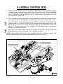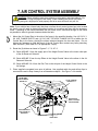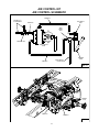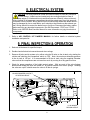
1
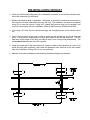
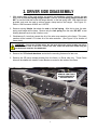
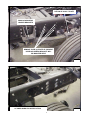
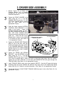
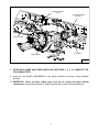
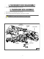
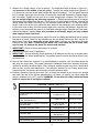
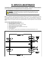
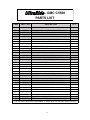
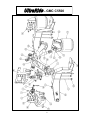
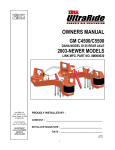
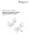
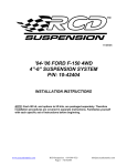
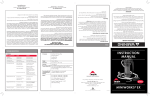
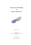
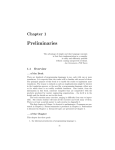
OWNERS MANUAL GMC C5500 15K AND 19K GVW CHASSIS CAB 2004-NEWER MODELS (Link Part No. 8M000050) Link Mfg. Ltd. 223 15th St. N.E. Sioux Center, IA USA 51250-2120 (712) 722-4868 Fax (712) 722-4779 QUESTIONS? CALL CUSTOMER SERVICE 1-800-248-3057 www.linkcmp.com PROUDLY INSTALLED BY : COMPANY : __________________________________________ INSTALLER SIGNATURE : ______________________________ DATE : _____________________ 80000988 SEP 1, 2015 1 INSTALLATION INSTRUCTIONS INDEX 1.0 INTRODUCTION 2.0 DRIVER SIDE DISASSEMBLY 3.0 DRIVER SIDE ASSEMBLY 4.0 PASSENGER SIDE DISASSEMBLY 5.0 PASSENGER SIDE ASSEMBLY 6.0 LATERAL CONTROL ROD 7.0 AIR CONTROL SYSTEM 8.0 ELECTRICAL 9.0 FINAL INSPECTION & OPERATION 10.0 SERVICE & MAINTENANCE 2 1. INTRODUCTION IMPORTANT! It is important that the entire installation instructions be read thoroughly before proceeding with suspension installation. WARNING! A correct installation must result in the suspension and axle being “loaded” within the range specified by axle and suspension manufacturers. Please check vehicle specifications and intended usage to insure axle will be within Gross Axle Weight Rating (GAWR). No alteration of any suspension component is permitted. PRODUCT INSTALLER RESPONSIBILITIES Installer is responsible for installing the product in accordance with Link Mfg. specifications and installation instructions. Installer is responsible for providing proper vehicle components and attachments as well as required or necessary clearance for suspension components, axles, wheels, tires, and other vehicle components to ensure a safe and sound installation and operation. Installer is responsible for advising the owner of proper use, service and maintenance required by the product and for supplying maintenance and other instruction as readily available from Link Mfg. INSTALLATION NOTES: Proper tightening of U-Bolt nuts and mounting nuts are required for proper operation. Need for proper Torque value is indicated by wrench symbol; values will be found in Table 10-1 in Maintenance section of the instructions. Failure to maintain proper torque can cause component failure, potentially resulting in accidents with consequent injury. No drilling of new frame holes is required for installation of the suspension. Mounting of the air control system will require holes to be drilled into the frame where necessary. Exhaust modification will be needed during the installation and is the responsibility of the installer. The GMC C5500 UltraRide with 15K rear axle and the 19K rear axle are shown throughout these installation instructions. The only difference between the suspensions for either axle depends on which shock is used. Both will follow the same sequence and setup as depicted. NOTE: When completing the installation of the UltraRide on the GM chassis, please refer to appropriate sections of the GM Service Manual for additional requirements. 3 PRE-INSTALLATION CHECKLIST Check the vehicle wheel alignment prior to installation to ensure no precondition already exists; record the information for verification. Remove the attached body, if applicable. Remember to disconnect all electrical connections to the body and fuel filler tube before removing the body. The installation can also be completed using a lift to raise the vehicle. If using a lift, chassis body removal may not be necessary, but removal of rear wheels will aid in installation. Refer to GM Document 812944 and 827666. If not using a lift, block the front wheels and apply the emergency brake so the vehicle cannot roll. Jack up the rear frame of the truck in order to unload the rear leaf springs (or use an overhead hoist). It may also be advantageous to place jack stands under the rear axle itself. This will take some of the weight off the axle, and help to keep it from moving during disassembly. The stands should not raise the tires off the ground. Install the suspension in the listed sequence. Install one side of the suspension at a time. First install the driver side completely, then install the passenger side. Removal of the rear wheels may aid in installation if using a lift, but it is not necessary. Measure & record the wheelbase and centering dims before beginning installation. 4 2. DRIVER SIDE DISASSEMBLY 1. With weight taken off the rear springs, as noted in pre-installation checklist, remove the rear bolts from the rear leaf spring hanger bracket. Remove the front spring hanger bracket. DO NOT re-use the bolts that mount the hanger bracket, or the leaf spring itself. New fasteners are provided, and must be used to achieve proper clamp load on the hanger. See Figure 2-1. Refer to GM Documents 800862 and 1202795. 2. Remove existing U-bolts that attach the axle to the leaf spring. After this is done, the axle, spring, and hanger will be loose. Remove only the leaf spring from the axle; DO NOT re-use CAUTION: Be careful theU-bolts leaf spring does not spring out of its hanger, or off the existing fasteners suchthat as the or nuts. frame. 3. Grind/remove 6 rivets that connect the aft of the axle cross-member to the frame. This crossmember will be located 9.72 inches aft of the axle centerline. (See Figure 2-2 for location of these rivets). WARNING! If truck has C5V042 option, the fuel tank will not be in this location but will be mounted further back on the truck. If this is the case, holes will need to be drilled using the provided paper template. Part # 80001039. 4. Remove the OEM shock absorbers and retain the mounting fasteners for later use. 5. Remove the OE jounce bumper bracket from the frame, on Driver side only. These Frame holes will be shared with Lateral Control Bracket, mounted to the inside of the frame. REMOVE OEM FRONT HANGER BRACKETS. DISCARD BOLTS FIG. 2-1 5 RETAIN OE U-BOLT PLATE REMOVE OEM REAR HANGER BRACKETS REMOVE THESE (6) RIVETS IF PRESENT. UPPER AIR SPRING BRACKET WILL BE MOUNTED HERE FIG. 2-2 PASSENGER SIDE VIEW SHOWING COMPLETION OF PREP WORK FOR INSTALLATION. FIG. 2-3 6 3. DRIVER SIDE ASSEMBLY 1. Review Figure 3-3 & Parts List/ Drawing (Section 10) to acquaint yourself with the various parts of the UltraRide suspension. 2. Fasten the FRONT HANGER to the frame using (6) 1/2 x 1 3/4 UNC FLANGE BOLTS and (6) 1/2 UNC TOP LOCK FLANGE NUTS, supplied with kit. (See Table 10-1 for appropriate Torque). 3. Place the frame mounted LATERAL CONTROL ROD BRACKET to the inside of the frame. Fasten this bracket to the frame using (4) 1/2 x 1 3/4 UNC FLANGE BOLTS and (4) 1/2 UNC TOP LOCK FLANGE NUTS, with bolts protruding through from the inside out. Place The OE Jounce Bumper back in place on the outside of the frame as it was. (See Table 10 -1 for appropriate Torque). FIG. 3-1 FRAME MOUNTED LATERAL CONTROL BRACKET OE JOUNCE BUMPER 4. Position the DRIVER SIDE TRAILING ARM on top of the axle, with front bushing mounted to the front surface of the HANGER BRACKET. Secure loosely with (2) 3/4 X 3 UNC FLANGE BOLTS AND (2) 3/4 UNC FLANGE NUTS. See Fig. 3-3. 5. Fasten the UPPER AIR SPRING BRACKET , and AIR SPRING to the FIG. 3-2 frame using (6) 1/2 X 1 3/4 UNC FLANGE BOLTS and (6) 1/2 UNC TOP LOCK FLANGE NUTS. Orient the bolts so that they point away from the vehicle. Tighten the 3/4 UNC JAM NUT on the lower AIR SPRING STUD that goes through the TRAILING ARM. (See Table 10-1 for appropriate Torque). 6. Install TRAILING ARM to axle using new supplied U-BOLTS. Use the OE upper leaf spring assembly plate and lower stabilizer bar plate as they were used in the original leaf spring setup. (See Fig 3-3) Tighten in a crisscross pattern. (See Table 10-1 for appropriate Torque). 7. Torque the (4) 3/4 X 3 UNC FRONT TRAILING ARM front pivot bolts. (See Table 10-1 for appropriate Torque). 7 HEIGHT CONTROL VALVE UPPER AIR SPRING BRACKET FRONT HANGER AIR SPRING TRAILING ARM FIG. 3-3 8. AFTER BOTH SIDES HAVE BEEN INSTALLED (SECTIONS 3, 4, 5, 6), COMPLETE THE FOLLOWING STEPS: 9. Install the new SHOCK ABSORBERS in the same orientation as factory, using hardware provided. 10. IMPORTANT: Route all brake cables away from the air spring and other moving components. It may need to be tied, or slightly repositioned in order to accommodate this. 8 4. PASSENGER SIDE DISASSEMBLY 1. Repeat Section 2 for the passenger’s side of the truck. 5. PASSENGER SIDE ASSEMBLY 1. Repeat Section 3 for the passenger’s side of the truck. 2. Check all clearance points and all alignments. See Figure 5-1 for details. IMPORTANT: Double-check all fasteners for proper torque. UPPER AIR SPRING BRACKET OE JOUNCE BUMPER FRONT HANGER TRAILING ARM AIR SPRING FIG. 5-1 9 6. LATERAL CONTROL ROD 1. Position AXLE MOUNTED LATERAL CONTROL ROD BRACKET onto axle as shown in Fig. 61. Mount Loosely to axle using (4) 5/8 UNF SQUARE U-BOLTS, (8) 5/8 SAE HARDENED WASHERS, and (8) 5/8 UNF HIGH NUTS. Note: If Truck uses Dana S150 axle (22k GVW truck), (4) SPACERS (Part No. 80001035) will be needed between this bracket and the axle itself as shown in the Parts List. 2. Check to make sure that the axle itself is centered between the frame rails by measuring from the outside of the driver and passenger side frame rails to the inside of the wheel hub, or tire. 3. Once both sides of the air suspension and both LATERAL CONTROL ROD BRACKETS are installed, mount the LATERAL CONTROL ROD between the two sides using (2) 5/8 X UNF BOLTS and (2) 5/8 UNF TOP LOCK NUTS (See Table 10-1 for appropriate Torque). See Figure 6-1 for details. Make sure when tightening that the lateral control rod connection maintains its transverse orientation. 4. With Truck set at Design Height (See Fig. 9-1), tighten (8) 5/8 UNF HIGH NUTS that were assembled loosely in step 1 (See Table 10-1 for appropriate Torque). NOTE: Inspect Lateral Control Rod for any interference with other components, paying close attention to clearance with any flexible components such as brake and fuel lines. LATERAL CONTROL ROD AXLE MOUNTED LATERAL CONTROL ROD BRACKET UPPER LATERAL CONTROL ROD MOUNT BRACKET FIG. 6-1 10 7. AIR CONTROL SYSTEM ASSEMBLY CAUTION! Route all airline away from exhaust, moving parts, and sharp objects. Be careful not to crimp the edges of the tubing. When installing the airline, fully insert into fitting and give a slight pull to seat properly and to be sure airline will not pull out. Note: If your vehicle has a frame body that does not allow the air control system box to be located as shown, you will need to determine another location for mounting and then drill the necessary holes. If installing on the frame underneath the cab, make sure it is mounted as high on the frame as possible to allow for ground clearance below the tank. 1. Mount the Air Control Box to the side of the frame in the specified location. Use (4) 5/16 X 1 3/4 UNF FLANGE BOLTS and (4) 5/16 UNF TOPLOCK FLANGE NUTS to fasten the Air Control Box to the frame, placing the rubber isolators between the box and frame. Do not tighten the fasteners so tight that back of the Air Control Box contacts any bolts protruding from the frame. (See Table 10-1 for appropriate Torque). 2. Route the (6) airlines as shown in Figures 7-1, 7-2, & 7-3. 2.1. Route AIRLINE 1 from the supply port of the Height Control Value to the lower outlet port of the Air Reservoir Solenoid. 2.2. Route AIRLINE 2 from the top Elbow in the Height Control Valve to the elbow in the Air Reservoir Solenoid. 2.3. Route AIRLINE 3 & 4 from the Run Tee on the del port of the Height Control Valve to the Air Springs. 3. Place supplied corrugated loom onto all airlines. Use supplied cable ties and airline clips to secure airline and to keep it away from all hazardous objects. See Figure 7-4 for details. FROM DUMP PORT ON AIR KIT AIRLINE # 2 TO AIR SPRINGS AIRLINE 3 & 4 ADJUSTABLE HEIGHT CONTROL VALVE LINKAGE FROM AIR SUPPLY PORT ON AIR KIT AIRLINE # 1 LEVER ARM 11 FIG. 7-1 AIR CONTROL KIT AIR CONTROL SCHEMATIC AIRLINE # 2 AIRLINE # 3 & 4 TO AIR SPRINGS PILOT SUPPLY PORT AIRLINE # 5 MAIN SUPPLY PORT AIR SUPPLY TEE HEIGHT CONTROL VALVE TO AIR CONTROL KIT AIR TANK AIRLINE # 1 SOLENOID VALVE FIG. 7-2 AIRLINES #3&4 AIRLINE # 2 AIRLINE # 1 FIG. 7-3 12 8. ELECTRICAL SYSTEM CAUTION! All wiring should be routed and secured neatly to avoid any functional or visual issues. Under-hood and under-body wire routings should be clear of sharp edges (3/4 inches minimum) and direct sources of heat (4 inches minimum). Wiring located in the passenger compartment should be routed away from high temperature areas over the muffler. Wiring should not be routed through wheel well areas where it may be damaged by tire or road debris, and it should not be routed over the exhaust system. Wiring should not contact the brake lines or fuel lines. Disconnect the battery cables before servicing any electrical components. See GM Documents 173237 and 173165. Refer to the GMT560 Best Practices Manual for more information on tying into electrical components. 1. Refer to AIR CONTROL KIT OWNERS MANUAL for further details on electrical system installation and parts list. 9. FINAL INSPECTION & OPERATION 1. Recheck all fasteners for specified torque. 2. Double-check all electrical connections and wire routings. 3. Remove all jacks and air system up by either using the fill valve on the air tank or by starting the vehicle and switching the compressor switch to “ON”. Note: the maximum allowable pressure in the air tank is 120 psi. It is recommended to fill the air tank using the supplied Schrader valve so that the compressors are not taxed too much by running for a long period of time. 4. Check for proper operation of the height control valves. With one end of the valve linkage disconnected rotate the valve arm down 45º, air should exhaust from the air springs. Rotating the valve arm up 45º should cause the valve to fill the air springs. FIG. 9-1 JOUNCE BUMPER CONTACT AT DESIGN HEIGHT 11.00 INCHES DESIGN HEIGHT 13 5. Measure the “Design Height” of the air springs. The height should be as shown in Figure 9-1, and measured at the middle of the air spring. To adjust the design height (see Figures 9-2, 9-3) disconnect one end of the valve linkage and adjust accordingly. Turn the plastic ball end joint to change the length of the linkage (increasing the length will increase the Design Height, and vise-versa). Tighten the lock nuts on the valve linkage when complete. See Figure 10-3. Set the design height by the following sequence: 1) Deflate the passenger side air bag by disconnecting the linkage from the arm. 2) With the driver side linkage connected, measure the design height and adjust accordingly by the methods mentioned above. 3) Once the design height is set for the driver side, repeat the same steps for the passenger side, including deflating the driver side air bag. Once the design height is set, reconnect the linkages. Jostle the suspension up and down and then allow it to come back to design height. Recheck the initial measurement and adjust if needed. Note: this procedure to set design height can only be done when empty or under light load. 6. Move the suspension through its entire range of motion by inflating and deflating the air springs to achieve full travel. Check for any interferences with the lateral control rod, axle, shocks, exhaust, frame, brake lines (especially on the driver side), fuel lines, etc. Reconnect the valve linkage to the lever. Note: if contacting the brake lines, hand caulk the line to make clearance at least 1/4” between the brake line and the axle brackets. 7. IMPORTANT! Check all fittings and airlines for air leaks. 8. Reinstall the chassis body (if applicable). 9. IMPORTANT! During servicing, check tightness of all fasteners and for any air system leaks. See Table 10-1 for torque specifications. Immediate corrective action should be taken if malfunctions occur. 10. After all final checks are complete, it is recommended to complete a full four-wheel alignment and drive line angle check. The pages following the installation instructions describe the proper method for checking driveline angles. Note: improper driveline angles may have a detrimental effect on ride, u-joints, and transmission. If any driveline vibration (or out of spec. angle measurement) occurs, use factory axle seat shims to modify driveline angle. 11. Kneeling Operation: Moving the switch “ON” to Dump will exhaust all air from the air springs and lower the rear of the vehicle approximately 3-4 inches. Air springs will inflate when the switch is returned to the “OFF” position. WARNING: Do not drive the vehicle while the Dump Switch is on and the air springs are deflated. TORQUE TABLE (Table 10-1) LOCATION FASTENER TORQUE FRAME MOUNTED FRONT HANGER 1/2 UNC NUTS 90-120 FT-LBS FRAME MOUNTED UPPER AIR SPRING BRACKET 1/2 UNC NUTS 90-120 FT-LBS FRAME MOUNTED LATERAL CONTROL ROD BRACKET 1/2 UNC NUTS 90-120 FT-LBS HIGH NUTS FOR 5/8 UNF U-BOLTS 130-170 FT-LBS 5/8 UNF NUTS 180-240 FT-LBS AIR SPRING STUD 3/4 UNC JAM NUTS 40-50 FT-LBS TRAILING ARM FLANGE NUTS FOR M20 U-BOLTS 250-325 FT-LBS FRONT TRAILING ARM PIVOT BOLTS 3/4 UNC NUTS 280-375 FT-LBS AIR CONTROL BOX 5/16 UNF NUTS 15-20 FT-LBS AXLE MOUNTED LATERAL CONTROL ROD BRACKET LATERAL CONTROL ROD 14 10. SERVICE & MAINTENANCE The UltraRide suspension needs no lubrication and little maintenance. The following components should be checked at the time the truck is being serviced. However, immediate corrective action should be taken if a serious malfunction occurs. See Exploded Assembly on following page for details. CAUTION! If maintenance or service is to be done on the air system, be sure to drain all air from system. Serious injury could occur if components are removed while system is full of air. Note: It is important to release any moisture contained within the air reservoir on a daily basis. This can be done by pulling on the cable attached to the drain valve. See Figure 7-3. Not releasing the moisture on a regular basis will cause the drain valve to not operate properly, and may cause the valve to malfunction. Excess moisture in the system can also cause premature failure of other components, as well as the tank itself. INSTALLATION & MAINTENANCE CHECK LIST Check and document OE rear axle alignment Set Design Height to 11.0 inches Verify suspension function via dump and re-inflation Check for air leaks and system integrity Check clearances throughout suspension motion range Check driveline angle 4 wheel alignment After installation, measure and record wheelbase and centering dims below (Fig. 10-2) 15 UltraRide — GMC C5500 PARTS LIST ITEM PART NO. DESCRIPTION QTY 1 2 13010062 13025090 VALVE-CONTROL, HEIGHT ELBOW, 1/4 TB 1/8 M-NPT, PUSH-IN DOT 1 2 3 13025497 RUN TEE-PLUG IN, 1/4" 1 4 13025499 ELBOW-PLUG-IN, 1/4" 1 5 14111614 1/2 X 1 3/4 UNC FLANGE BOLT (GRADE 8) 28 6 14882002 5/8 HARDENED WASHER, ZINC PLATED 8 7 14950029 U-BOLT-SQUARE, 5/8 UNF, 5.06 X 7.00 4 8 14950030 U-BOLT, M20 X 2.50, 79 X 465 4 9 29910024 PIVOT BALL KIT 2 10 80001035 ADAPTER-AXLE, GM5500HD, 15K 4 11 1103-0505 SPRING-AIR 2 12 * SEE NOTE SHOCK ABSORBER 2 13 1302-2014 REDUCER, 1/8 F-NPT 1/4 M-NPT 2 14 140D-2022 5/8 X 2 3/4 UNF HEX CAP SCR (GR 8) O&P 4 15 141A2424 3/4 X 3 UNC FLANGE BOLT (GR 8) O&P 4 16 1474-1600 1/2 UNC HEX JAM NUT 4 17 1475-2402 3/4 UNF HEX JAM NUT, O&P 2 18 1477-2006 5/8 UNF HEX TOP LOCK NUT (GR C) O&P 4 19 1480-1604 1/2 UNC TOP LOCK FL NUT (GR G) O&P 28 20 1480-2002 HEX TOP LOCK FLANGE NUT, M20 X 2.5, CLASS10 8 21 1480-2404 3/4 UNC TOP LOCK FL NUT (GR G) O&P 4 22 1500-0245 LINKAGE-VALVE, HEIGHT CONTROL (3.88) 1 23 1500-0303 SNAP BUSHING (.250 MAT'L) 2 24 1506-0016 5/8 UNF HEX HIGH NUT 8 25 800M0086 BRACKET-MOUNT, LCR, UPPER 1 26 800M0087 BRACKET-MOUNT, LCR, LOWER 1 27 800M0088 LATERAL CONTROL ROD 1 28 810M0025 HANGER 1 29 810M0026 HANGER 1 30 810M0028 BRACKET-MOUNT, AIRSPRING 1 31 810M0029 BRACKET-MOUNT, AIRSPRING 1 32 820M0011 ARM 2 * - THE 15K AXLE USES SHOCK ABSORBER 1210-0506 AND THE 19K AXLE USES 1210-0511. 16 UltraRide — GMC C5500 17 UltraRide - TROUBLESHOOTING GUIDE COMPONENT POSSIBLE PROBLEM CORRECTIVE ACTION Airlines Air leaks Replace airline Fittings Air leaks Remove fitting and apply fresh joint compound. Reinstall fitting, but Do Not Over tighten. Do not use Teflon tape. A. Improper height A. Adjust valve linkage to maintain proper air spring height. Air Springs B. Air leakage B. Replace air spring. A. Air spring(s) will not inflate when weight is added to the chassis. Height Control Valve* OR Air spring(s) will not deflate when weight is removed from the chassis. Inspect valves to insure drive bearing notch is located correctly. The driver side valve notch on “SUPPLY” port side of valve, passenger side on “SUSP” port side. If not, loosen lever screw (but do not remove completely) and pull lever loose from drive bearing, rotate drive bearing until the drive bearing notch is in the correct position and re-secure lever by tightening lever screw. See Fig. 11-3 & 11-4 for orientation details B. Replace valve. Shock Absorber Lateral Control Rod Insufficient damping effect Replace shocks A. Loose nuts on lateral control rod bolts A. Tighten securely. B. Worn bushings B. Replace lateral control rod. 18 GMC C5500 OWNERS GUIDELINES The UltraRide suspension needs no lubrication, and little maintenance. However, immediate corrective action should be taken if a serious malfunction occurs. CAUTION! If maintenance or service is to be done on the air system, be sure to drain all air from the system. Serious injury could occur if components are removed while system is full of air. PRODUCT OWNER RESPONSIBILITIES Owner is solely responsible for pre-operation inspection, periodic inspections, maintenance, and use of the product as specified in the particular LINK MFG. instructions available by product model, except as provided in this warranty, and for maintenance of other vehicle components. Of particular importance is the re-torque of fasteners including axle u-bolts, torque rod bolts, and track rod bolts. This re-torque must be performed within 90 days of the suspension being put in service. Owner is responsible for “down time” expenses, cargo damage, and all business costs and losses resulting from a warrantable failure. The UltraRide Chassis Air Suspension is fully automatic in controlling the height of the chassis. No manual intervention to control air pressure or ride height is needed during the course of operation. The Compressor Switch must be on for the compressors to operate. During difficult starting circumstances, (i.e. extremely cold weather) it is recommended to turn the compressor switch off until the vehicle is running, so it will not draw current from the battery. The compressors are controlled by the pressure switch located in the Air Control Box. This switch automatically turns the compressors on when the tank pressure falls below 100 psi, and turns them off at 120 psi. The Low Pressure Warning Light indicates a severe drop in tank pressure (below 60 psi). Immediate corrective action should be taken to determine the cause of air loss. Compressor switch should be turned off if Low Pressure Warning Light is on, and remains on even after the compressors have run for a normal period of time. NOTE: The Low Pressure Warning Light could come on briefly when the “Dump” feature is being used. It is important to release any moisture contained within the air tank on a daily basis. This is done by pulling on the attached release cable for approximately 5 seconds. See Air Control Kit Owners Manual for location of this cable. Not releasing the moisture on a regular basis will cause the drain valve to not operate properly. CHECK AT EVERY VEHICLE SERVICE INTERVAL: Check Design Height ±¼”. Check for air leaks around fittings. CHECK AFTER THE FIRST 1000 MILES: Recheck & tighten any loose fasteners. Check for any loose or worn components. CHECK AFTER EVERY 30,000 MILES: Check arm pivot bushings and lateral control rod bushings for wear; replace if worn 19 20 21 22