1
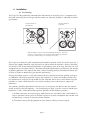
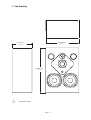
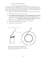
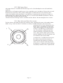
H
Q
2
1
0
User Manual
Quested Monitoring Systems
Table of Contents
1. Introduction . . . . . . . . . . . . . . . . . . . . . . . . . . . . . . . . . . . . . . . . . . . . . . . . . . . . . . .3
2. Safety considerations
2.1 General . . . . . . . . . . . . . . . . . . . . . . . . . . . . . . . . . . . . . . . . . . . . . . . . . . . . . .4
2.2 Hearing damage . . . . . . . . . . . . . . . . . . . . . . . . . . . . . . . . . . . . . . . . . . . . . . .4
3. Unpacking . . . . . . . . . . . . . . . . . . . . . . . . . . . . . . . . . . . . . . . . . . . . . . . . . . . . . . . .4
4. Installation . . . . . . . . . . . . . . . . . . . . . . . . . . . . . . . . . . . . . . . . . . . . . . . . . . . . . . . .5
4.1 Positioning . . . . . . . . . . . . . . . . . . . . . . . . . . . . . . . . . . . . . . . . . . . . . . . . . . .5
5. Audio connections . . . . . . . . . . . . . . . . . . . . . . . . . . . . . . . . . . . . . . . . . . . . . . . .7
5.1 Definitions . . . . . . . . . . . . . . . . . . . . . . . . . . . . . . . . . . . . . . . . . . . . . . . . . . .7
5.2 Passive Operation . . . . . . . . . . . . . . . . . . . . . . . . . . . . . . . . . . . . . . . . . . . . .8
5.3 Bi-Amped Operation . . . . . . . . . . . . . . . . . . . . . . . . . . . . . . . . . . . . . . . . . .10
5.4 Tri-Amped Operation . . . . . . . . . . . . . . . . . . . . . . . . . . . . . . . . . . . . . . . . . .10
5.5 2 Way Active . . . . . . . . . . . . . . . . . . . . . . . . . . . . . . . . . . . . . . . . . . . . . . . . .11
5.5.1 Converting from passive if speakers are free standing . . . . . . . . . . . . . . . .11
5.5.2 Converting from passive if speakers are soffit mounted . . . . . . . . . . . . . . .11
5.6 3 Way Active . . . . . . . . . . . . . . . . . . . . . . . . . . . . . . . . . . . . . . . . . . . . . . . . .12
5.6.1 Converting from passive or bi-amped if speakers are free standing . . . . . . .12
5.6.2 Converting from passive or bi-amped if speakers are soffit mounted . . . . . .12
5.7 Cable . . . . . . . . . . . . . . . . . . . . . . . . . . . . . . . . . . . . . . . . . . . . . . . . . . . . . . . .12
6. Technical specification . . . . . . . . . . . . . . . . . . . . . . . . . . . . . . . . . . . . . . . . . . . .13
7. Line Drawing . . . . . . . . . . . . . . . . . . . . . . . . . . . . . . . . . . . . . . . . . . . . . . . . . . . . . .14
8. Guarantee . . . . . . . . . . . . . . . . . . . . . . . . . . . . . . . . . . . . . . . . . . . . . . . . . . . . . . . .15
9. Appendix . . . . . . . . . . . . . . . . . . . . . . . . . . . . . . . . . . . . . . . . . . . . . . . . . . . . . . . . .15
9.1 Accessories . . . . . . . . . . . . . . . . . . . . . . . . . . . . . . . . . . . . . . . . . . . . . . . . . . .15
9.2 Spares . . . . . . . . . . . . . . . . . . . . . . . . . . . . . . . . . . . . . . . . . . . . . . . . . . . . . . .15
9.3 Driver replacement procedure . . . . . . . . . . . . . . . . . . . . . . . . . . . . . . . . . . . .16
9.3.1 Tweeter & tweeter diaphragm . . . . . . . . . . . . . . . . . . . . . . . . . . . . . . . . . .16
9.3.2 Mid range driver . . . . . . . . . . . . . . . . . . . . . . . . . . . . . . . . . . . . . . . . . . .17
9.3.3 Bass Driver . . . . . . . . . . . . . . . . . . . . . . . . . . . . . . . . . . . . . . . . . . . . . . . .17
1. Introduction
Thank you for purchasing your Quested product and whether it is a pair of passive monitors or a
4 way active system you can be assured the same care has gone into its design and manufacture.
You can be sure you have purchased one of the finest monitors in the world and if you take time
and care in positioning and aligning the system you will appreciate why Quested monitors have
a reputation for faithful reproduction covering the entire audible spectrum. They are professional
monitors, and are not designed to flatter, but faithfully reproduce. Please take care to maintain
the system and you will obtain many years of service
Please take the trouble to complete the registration form that came with your monitors. This will
help us in the future, should you raise any queries. If you have any questions please address
them to your Quested representative, who will then refer back to the designer and manufacturer
if necessary. In this way, you will be assured in obtaining the best possible performance and long
term reliability of your system.
This manual covers the HQ210 3 way passive monitor.
Please read this manual, which we have kept as concise as possible, it really will help you and
covers important safety considerations.
The HQ210 is a 3 way passive monitor that can be used soffit mounted or free standing and the
ability to rotate the mid/hi baffle enables the speaker to be installed in a horizontal or vertical
orientation. They are suitable for use as main monitors in mid sized control rooms or as mid field
reference monitors in large rooms.
Typical applications include post production suites, broadcast, project studios, surround sound,
mastering suites and main monitors in medium sized control rooms.
The HQ210 monitors can be run passively with the ability to bi or tri-wire and can also be run bi
or tri-amped. They also have the ability to be run 2 way or 3 way active but will need the addition of an external electronic crossover, and to take advantage of the additional power that will
be available some of the drivers should be upgraded.
A pair of HQ210 are ideally driven by a Quested AP800 amplifier, but other amplifiers with a
power output of between 200-700 watts RMS per channel can be used.
The low frequency performance is more than adequate for most situations, but can be further
extended by combining it with the VS1115 15” sub bass to extend the frequency response down
to 20Hz. The VS1115 is also ideal when a discrete sub channel is required when using formats
such as Dolby 5.1
Page 3
2. Safety Considerations
2.1 General
THE HQ210 HAS BEEN DESIGNED IN ACCORDANCE WITH INTERNATIONAL SAFETY STANDARDS.
THE FOLLOWING WARNINGS MUST BE FOLLOWED TO ENSURE SAFE OPERATION OF THIS EQUIPMENT.
CAUTION:
THIS
UNIT CONTAINS MAGNETIC COMPONENTS WHICH MAY EFFECT ADJACENT
SUSCEPTIBLE EQUIPMENT.
2.2 Hearing Damage
This equipment can deliver sound pressure levels in excess of 112dB. At this level permanent hearing damage can occur and exposure to this level of sound, even for relatively short periods (see
table below), can be harmful. Of equal importance to the maximum level of sound is the exposure
to high levels of sound for extended periods. There are no international agreed limits and different
countries have different limits measured in differing ways. IT IS THEREFORE IMPORTANT THAT THE USER
ESTABLISHES THE RECOMMENDED, AND IN SOME TERRITORIES, LEGAL LIMITS, THAT ARE IN PLACE.
As a guide the table below shows the levels that are acceptable in the majority of Western Europe
and the US & Canada.
SPL dB(A)
Listening time per day
90
95
100
105
110
115 and over
8 hours
2.4 hours
40 minutes
15 minutes
5 minutes
Not at all
It is also important to note that the effect of exposure to sound is cumulative. Having listened to sound, for example, for 15 minutes at 105 dB then further exposure to noise levels
above 80dB should be avoided until the next day.
3. Unpacking
This Quested product has been carefully manufactured, tested and packed to ensure it arrives in a
flawless condition. The component parts of the packing have been thoughtfully designed to offer sufficient protection during transportation, yet remain fully recyclable and should be retained for future
use.
Page 4
4. Installation
4.1 Positioning
The HQ210 is designed to be mounted either horizontally or vertically, but it is important that
the baffle containing the mid range and the tweeter are correctly aligned as indicated in the diagram below.
HQ210 mounted
Vertically
HQ210 mounted
horizontally
Note the baffle is taken out and turnd through 90 degrees when the
cabinet is changed from vertical to horizontal mounting so that the
the tweeter and mid range are still aligned vertically.
The HQ210 can either be soffit mounted or positioned on speaker stands, but which ever way is
chosen, the support should be rigid and must not vibrate when the monitor is driven. Vibrations
will result in lack of low frequency definition. Its positioning close to or away from the rear wall
and proximity to any room corners is best determined by experimenting and placing the speaker
in differing positions. The shape of the room, normal listening position and room treatment will
all have an effect on determining the speakers positioning.
Placing the cabinet against a wall will reinforce the bass performance of the speaker and up to
an additional 3dB may be obtained. Placing the monitors in a corner will further reinforce the
bass performance and gains of up to 6dB may be achieved, but be very careful about siting the
monitors in a room corner because it can excite standing waves and create an unpleasant
boominess.
The speakers should be positioned so that the axis (an imaginary line drawn from the acoustic
centre of the left and right monitor — see line drawing on page 14 of this manual) should cross
between 0.5 and 1 meter behind the engineers position, for the following reasons:a) To obtain the most accurate imaging, both front to rear and side to side, and to obtain as
large as possible listening area so that the engineer can move and operate the console without perceiving a change in character of the monitors.
b) To enable listening for long periods of time without suffering strain or fatigue.
Page 5
Sketch showing positioning of speakers. The speakers should be between 2.5 - 3.4 meters apart and the axis of
the speakers should cross between 0.5 and 1 meter behind the listening position
2.5 - 3.4 mtrs
The height of mounting the speaker is equally as important. The correct height should result in the axis
being at ear level when the engineer is sitting in his normal position at the console.
Page 6
5 Audio Connections
|
The connection to the HQ210 is through a triple pair terminal tray which accepts either bare end
cables or 4mm banana plugs. Each pair of terminals corresponds to individual sets of drivers and
are marked accordingly with Hi, Mid & Lo.
+
Hi
Mid
Lo
5.1 Definitions
The terms tri-wired, bi-amped etc. can be confusing as they are not always used consistently, so the
following definitions indicate the meaning as used in this manual.
Passive One amplifier channel is used for all the monitor drive units. An internal passive crossover
separates the programme frequencies and directs them to the appropriate drive units. On the
HQ210 the input to each section of the internal crossover is available on separate terminal connections to facilitate a number of different wiring options.
Bi-wired This is a wiring option when running the monitors in the passive mode. Here the single
channel amplifier has a pair of twin cables running between its output terminals and the input terminal tray of the monitor. Generally the bass driver would be driven from one cable and the mid
and high drivers together from the other cable. Tri-Wired This is a wiring option when running the
monitors in the passive mode. Here the single channel amplifier has 3 twin cables running between
its output terminals and the input terminal tray of the monitor. Each set of drive units (bass, mid &
high) in the monitor will be run from its own cable.
Bi-Amped 2 amplifier channels are used for each monitor. One amplifier channel will drive the
bass, the other the mids & highs together. Both channels will use the internal passive crossover,
therefore this is not the same as running the speakers 2 way active where the bass would be driven
directly from the amplifier without the signal passing through the internal crossover.
Page 7
The mid and high would use a separate amplifier channel with the mid being driven directly from
the amplifier and the high through the internal passive crossover. This method of running the monitors would require the use of an external electronic crossover.
Tri-Amped 3 amplifier channels are used for each monitor. One amplifier channel will drive the
bass, another the mids and the 3rd the highs. All channels will use the internal passive crossover,
therefore this is not the same as running the speakers 3 way active where each set of drive units
(bass, mid & high are driven directly from the amplifier without the signal passing through the
internal crossover. This method of running the monitors would require the use of an external electronic crossover.
5.2 Passive operation
When run passively the the programming plug on the passive crossover circuit board
must be plugged into the socket CN3, marked as passive. This is how the speaker is set up at
the time of shipment from the factory when supplied as passive. See page 11 & 12 on changing
the position of the programming plug if converting the speaker to passive from 2 or 3 way active.
These monitors can either be installed with a single twin cable, 2 twin cables (bi-wired) or 3 twin
cables (tri-wired). It is recommended that the monitors are installed bi or tri-wired. This will make
a small improvement in sound quality by minimising distortions produced by voltage losses associated with the interaction of signal currents flowing through the loudspeaker cables. If the speak-
ers are to be soffit mounted and there is any intention to convert to bi or tri-amped
operation then the speakers should be bi or tri-wired to avoid the need to remove the
speakers from their soffit mounting position when converting.
If installing with a single twin cable the hot or positive wire should be connected to the appropriate terminal marked (+) and having the red marking round the screw down knob. The cold or negative wire should be connected to the corresponding terminal marked (-) and having the black
marking round the screw down knob. The brass connecting links between the 3 (+) terminals and
those linking the 3 (-) terminals, should remain in place.
Passive operation: The connection from the amplifier can be
to any of the terminals, but the connecting links must be kept
in place. The hot or positive wire to the terminal marked (+) red.
and the cold or negative wire should be connected to the
terminal marked (-) black.
AMPLIFIER
or
or
All links remain in place
Page 8
If the speakers are to be bi-wired there will be a pair of twin cables from the amplifier. One twin
cable should be connected to the terminal marked lo and the links between it and the terminals
marked mid should be removed. The other cable can be connected to either the terminals marked
Mid or Hi, but the links must remain in place. With both twin cables the hot or positive wire
should go to the (+) terminals and the cold or negative wire to the (-) terminals.
Passive operation, but with bi-wired connection. A pair of twin cables
is run from the amplifier. One wire should be connected to the terminal
marked Lo and the links between Lo & Mid should be removed.
The other wire can be connected to either the terminal marked Mid or Hi
but links must remain in place. With both the twin cables the hot or positive
wire should go to the (+) red terminal and the cold or negative wire to the
(-) black terminal.
Hi
or
AMPLIFIER
Mid
and
Lo
Links between Lo & Mid removed
If the speakers are to be tri-wired there will be 3 twin cables from the amplifier. The hot or positive cables should be connected to the 3(+) terminals and the cold or negative cables to the 3(-)
terminals and all the connecting links removed.
Hi
Passive operation, but with tri-wired connection : 3 twin cables are run from
the amplifier. One wire should be connected to the terminal marked Lo, the
second to the terminal marked mid and the final wire connected to the terminal
marked Hi. All links should be removed. The hot or positve wire should go to
the (+) red terminal and the cold or negative wire to the (-) black terminal.
AMPLIFIER
Mid
Lo
All links removed
Page 9
5.3 Bi-Amped Operation
If the speakers are to be run bi-amped 2 amplifier channels will be used to drive each monitor.
One amp channel should be connected to the either the terminal marked Mid or Hi and the link
between these terminals kept in place. Another channel should be connected to the terminal
marked Lo and the links between the mid and lo terminals should be removed.
Bi-amped operation will allow the use of two lower powered amps, rather than a single high powered amp when the HQ210 is driven passively, so might be useful when upgrading from smaller
monitors, or, for example, a specialist/esoteric valve amp. is required to drive the mid & hi drivers.
5.4 Tri-Amped Operation
Amplifier 1 should drive the mid & hi. The connection from this amplifier should be to either
the terminal marked Mid or Hi and the link between the terminals should be kept in place
Amplifier 2 will drive the lo. The connection from this amplifier should be to the terminal
marked Lo and the link between terminals marked Mid & Lo should be removed.
With both twin cables the hot or positive wire should go to the (+) red terminal and the cold
or negative wire to the (-) black terminal.
Hi
AMPLIFIER 1
or
AMPLIFIER 2
Mid
and
Lo
Links between Lo & Mid removed
If the speakers are to be run tri-amped 3 amplifier channels will be used to drive each monitor.
One amp. channel should be connected to the terminal marked Hi, another channel should be
connected to the terminal marked Mid and the third channel should be connected to the terminal
marked Lo. All the links should be removed. The same comments regarding the use of lower powered/specialist amps as noted under bi-amped operation in the above paragraph applies.
Amplifier 1 should drive the hi and the connection from this amplifier should be to the terminal
marked Hi. Amplifier 2 should drive the mid and the connection from this amplifier should be to
terminal marked Mid. Amplifier 3 should drive the lo and the connection from this amplifier should be to
terminal marked Lo. All terminal links should be removed. With the three twin cables the hot or positive
wire should go to the (+) red terminal and the cold or negative wire to the (-) black terminal.
Hi
AMPLIFIER 1
AMPLIFIER 2
Mid
AMPLIFIER 3
Lo
All links removed
Page10
5.5 2 Way Active
If the monitors are shipped set up for bi-amped operation then the following connections should be
made
The link connecting the terminals marked Lo & Mid for both the hot (+) and cold (-) should have
been removed. The cable that runs from the amplifier/amplifier channel chosen to drive the bass drivers should be connected to terminals marked lo and the cable that runs from the amplifier/amplifier
channel chosen to drive the mid & high drivers should be connected to either of the terminals
marked mid or high. Remember to leave the link connecting the mid and hi terminals in
place.unless the mid/high speakers are to be run bi-wired (separate cables for the mids & highs, but
still though the passive crossover) then the link should be removed and the cable run to both the
mid and hi terminals. In all cases the hot or positive cable should go to the terminal marked (+) and
the cold or negative cable to the terminal marked -).
If the monitors are being converted from passive operation the following instructions should be
noted.
When the HQ210 is shipped direct from the factory the LS2500 (Quested part number Q01-0030)
bass drivers are fitted. These drivers are capable of handling greater power and it is recommended
that if you are converting passive monitors you also upgrade the bass drivers.
Whether new drivers are fitted or not, it will be necessary to change the connection on the passive
crossover as follows:
5.5.1 Converting from passive if the speakers are free standing:a)
b)
c)
d)
Remove the six M5 countersunk socket screws that hold the terminal tray mounting board.
Remove the complete assembly which contains the passive crossover, the wooden mounting
board and the terminal tray. Be careful not to put strain on the cables that run to the speakers.
On the crossover circuit board, locate the programming plug CN2 which will be plugged into
socket CN3, marked as passive. Disconnect the programming plug by gripping the sides and
pulling. Finally reconnect the plug into socket CN4, marked as ‘2 W-Active’
Replace the complete assembly and screw back in place with M5 socket screws
5.5.2 Converting from passive if the speakers are soffit mounted:There will no need to remove the monitors as long as they have been bi or tri-wired as detailed in
5.2 above.
a)
b)
c)
d)
e)
Remove the left hand bass driver by undoing the four M5 socket cap screws.
Disconnect the crimp connectors noting colour coding of wiring to the loudspeaker terminals.
Pull away the felt at the rear of the cabinet (this has been tack stapled so will be easy to pull
away). This will reveal the passive crossover.
Repeat procedure as in 5.5.1 c) above.
The felt should then be tacked back into place and the bass driver reconnected.
Page 11
5.6 3 Way-Active
If the monitors are set up for 3 way-active operation then the following connections should be
made.
All the links connecting the terminals should have been removed. The cable which runs from the
amplifier chosen to drive the bass drivers should be connected to the terminals marked lo. The
cable running from the amplifier chosen to drive the mids should be connected to the terminal
marked as mid and the cable running from the amplifier chosen to drive the high frequency units
should be connected to the terminal marked hi.
In all cases the hot or positive cable should go to the terminals marked (+) and the cold or negative
cable to the terminals marked as (-).
If the monitors are being converted from passive or bi-amped operation the following instructions
should be noted.
When the active monitors are shipped from the factory the following upgraded drivers are fitted to
the HQ210 Active.
Bass Drivers - LS2500 (Quested part number Q01-0030)
Mid Drivers - MD3SD (Quested part number Q02-0030)
HF Units - TW34 (Quested part number Q03-0030)
It is strongly recommended that if you are converting passive or bi-amped monitors you also
upgrade the bass drivers to the LS2500 and fit a new mid/hi baffle containing the MD3SD and
TW34.
It will then be necessary to change the connection on the passive crossover.
5.6.1 Converting from passive or bi-amped if the speakers are free
standing:Repeat the procedure as in 5.5.1above, except reconnect the programming plug CN2 into socket
CN5, marked as 3 way-active.
5.6.2 Converting from passive or bi-amped if the speakers are soffit
mounted
There will be no need to remove the monitors as long as they have been tri-wired as detailed
above.
Repeat the procedure as in 5.5.2 above, except reconnect the programming plug CN2 into socket
CN5, marked as 3 way-active.
5.7 Cable
When running speaker cables it is important that good quality oxygen free cable (OFC) is used. If
the connection is with a single pair of cables 4mm2 speaker cable should be used, with bi/tri wired
connections, 2,0mm2 cable should be run.
Page 12
6. Technical Specification
Size (w x h x d):
590 x 850 x 355mm ( 23” x 33” x 14”)
Weight:
60kgs (132lbs)
Drivers:
Bass 2 x 254mm (10”) cone
Mid Range 1 x 75mm (3”) soft dome
High Frequency 1 x 28mm(11/8”) soft dome
Maximum SPL:
112dB(C)
Sensitivity:
91.5dB at 1 watt at 1 meter
Frequency Response:
40Hz-18kHz ±2dB
Nominal Impedance:
8Ω
Connectors:
Triple pair gold plated binding posts for 4mm banana or
bare wire allowing connection through the passive
crossover to the individual sets of drivers
Crossover:
Multipole network utilising polypropylene capacitors and
air cored inductors throughout.
Power requirements:
Amplifier rating at 8ohm between 300-900 watts RMS
This product is built to conform to the requirements for CE marking
Page 13
7. Line Drawing
590.00 mm
23.23 "
355.00 mm
13.98 "
850.00 mm
33.46 "
Acoustic Centre
Page 14
8. Guarantee
The HQ210 is guaranteed for 24 months from its date of purchase. If any part of the product is
found defective due to faulty manufacture within 24 months from the date of purchase, Quested,
through its authorised distribution network will effect repair or replacement, at its discretion, free of
charge providing:a)
The fault is reported to the authorised distributor.
b)
Proof of purchase is provided.
c)
The fault is not caused by, misuse, neglect, or faulty operation by the user.
d)
The fault is not a result of fair wear & tear
e)
The equipment has not been modified in any way
f)
The equipment has not been taken apart or tampered with in any way other than
described in the service manual for the adjustment and replacement of user accessible
items.
The guarantee does not cover
a)
Damage during transit
b)
Damage to diaphragms, cones and other speaker parts as a result of the over-driving of
the monitors or by faulty installation or connection.
c)
Damage caused by incorrect installation or during installation caused by incorrect handling.
d)
The cost of carriage to or from the authorised repairer.
9. Appendix
9.1 Accessories
Accessory
TW30DMS
Part Number
Q03-0011
Shielded Tweeter
9.2 Spares
Spare part Description
LS 2505mm
(10”) Loudspeaker
MD75D
3” midrange soft dome
Part Number
Q01-0035
Q02-0040
TW30
28mm (11/8”) soft dome
Q03-0010
RD30
28mm (11/8”) soft dome diaphragm
10” Loudspeaker recone
Q53-0010
RC2505
Page 15
Q50-0035
9.3 Driver replacement procedures
9.3.1 Tweeter and tweeter diaphragm
The tweeter is held in by 3 self tapping wood screws. Remove these with a posidrive no. 2 screwdriver. Take out the tweeter and disconnect the two wires, noting which colour goes to which terminal. If on removing the 3 screws that hold the tweeter there is any difficulty in removing the unit
do not try to force a blade between the cabinet and tweeter, but use a small narrow bladed screwdriver in one of the screw holes to gently lever out the tweeter.
a)
Remove the 3 machine screws on the front plate of the tweeter using a 2mm hex driver.
b)
De-solder and unwind wires from the terminal tags
c)
Remove diaphragm assembly and replace with the new diaphragm. The Ferrofluid has
the appearance of oil and is dark brown in colour and should cover about 1/3 of the
coil. If there is less than this then additional Ferrofluid should be added. This can be
obtained from your dealer/distributor or directly from Quested. The ferrofluid reference
is
It should be noted that ferrofluid is best added as shown in the
diagram below. The fluid should never cover more than 1/2 the coil.
d)
Wrap the wires from the diaphragm around the corresponding tags
e)
Keep the wire slightly taught, but do not strain
f)
Re-solder the wires and re-assemble.
Wire with curved loop formed at one end
2
1
Ferrofluid
Tweeter
Dip wire in ferrofluid, a small amount will be retained on the wire
hold wire over the tweeter gap and the magnet will attract the
fluid from the wire into the gap. Do this 3 or 4 times in different
position on the tweeter, then check by inserting the new diaphragm
to see the amount of fluid in the tweeter.
Page 16
9.3.2 Mid range driver
No recone kit that is available for the mid range so if a fault develops the unit will need to be
replaced.
Remove the 4 self tapping wood screws using a posidrive no.2 screwdriver. Take out the unit and
disconnect the two wires, noting which colour goes to which terminal. If on removing the 4
screws that hold the mid range there is any difficulty in removing the unit do not try to force a
blade between the cabinet and mid range, but use a small narrow bladed screwdriver in one of
the screw holes to gently lever out the unit.
Connect the new mid range and re assemble into the cabinet. Do not overtighten the 4 screws.
9.3.3 Bass driver and bass driver recone.
The bass drivers are held in by four M5 machine screws. Remove the screws in the order shown
below using a 4mm hex driver The drivers are heavy so hold the driver by the frame when
removing the last screw. Remove the bass
driver, using a screwdriver in one of the
screw holes to gently lever out the driver
1
if there is any difficulty in removing the
3
unit. Do not force a blade between the
cabinet and driver. Disconnect the two
wires, noting which colour goes to which
terminal. Replace with the new driver and
re-assemble in the reverse order.
4
2
Page 17
A recone unit is available for the HQ210
bass driver. Instruction for reconing is
included with the recone kit. However,
unless you are familiar with the practice
of reconing it is better to have the speaker
reconed by someone who is experienced.