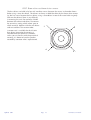
1
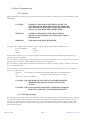
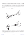
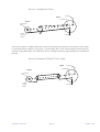
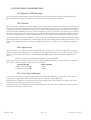
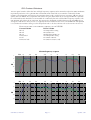
V
S
2
1
0
8
USER MANUAL
QUESTED MONITORING SYSTEMS
1.
INTRODUCTION . . . . . . . . . . . . . . . . . . . . . . . . . . . 3
2.
SAFETY CONSIDERATIONS . . . . . . . . . . . . . . . . . 4
2.1. General . . . . . . . . . . . . . . . . . . . . . . . . . . . . . 4
2.2. Hearing damage. . . . . . . . . . . . . . . . . . . . . . . 4
3. UNPACKING . . . . . . . . . . . . . . . . . . . . . . . . . . . . . . . . . 5
4. INSTALLATION . . . . . . . . . . . . . . . . . . . . . . . . . . . . . . . 6
4.1. Positioning . . . . . . . . . . . . . . . . . . . . . . . . . . . 6
4.2. Aligning the speakers . . . . . . . . . . . . . . . . . . 6
4.3. Electrical connections. . . . . . . . . . . . . . . . . . 8
4.3.1. Safety Earthing . . . . . . . . . . . . . . . . . . . 8
4.3.2. Voltage Setting. . . . . . . . . . . . . . . . . . . 8
4.3.3. Fuse Setting . . . . . . . . . . . . . . . . . . . . . 9
4.4. Rear panel detail . . . . . . . . . . . . . . . . . . . . . . 9
4.5. Audio connections. . . . . . . . . . . . . . . . . . . . . 10
5. OPERATIONAL CONSIDERATIONS . . . . . . . . . . . . . . . . 12
5.1. Mains On-Off Switching. . . . . . . . . . . . . . . . . 12
5.2. Thermal. . . . . . . . . . . . . . . . . . . . . . . . . . . . . . 12
5.3. Signal Level. . . . . . . . . . . . . . . . . . . . . . . . . . . 12
5.4. Front Panel Indicator. . . . . . . . . . . . . . . . . . . 12
5.5. Contour Selectors. . . . . . . . . . . . . . . . . . . . . 13
6. TECHNICAL SPECIFICATION. . . . . . . . . . . . . . . . . . . . . 14
7. LINE DRAWING . . . . . . . . . . . . . . . . . . . . . . . . . . . . . . . 15
8. GUARANTEE. . . . . . . . . . . . . . . . . . . . . . . . . . . . . . . . . 16
9. APPENDIX . . . . . . . . . . . . . . . . . . . . . . . . . . . . . . . . . . 16
9.1. Accessories . . . . . . . . . . . . . . . . . . . . . . . . . . 16
9.2. Spares . . . . . . . . . . . . . . . . . . . . . . . . . . . . . 16
9.3 Driver replacement . . . . . . . . . . . . . . . . . . . . . 17
1. INTRODUCTION
Thank you for purchasing your Quested monitor system and whether it is a pair of passive monitors or a 4 way
active system you can be assured the same care has gone into its design and manufacture. You can be certain you
have purchased one of the finest monitors in the world and if you take time and care in positioning and aligning
the system you will appreciate why Quested monitors have a reputation for faithful reproduction covering the
entire audible spectrum. They are professional monitors, and therefore are not designed to flatter but faithfully
reproduce. Please take care to maintain the system and you will obtain many years of service.
Please take the trouble to complete the registration form that came with your monitors. This will help us in the
future should you raise any queries. If you have any questions please address them to your Quested representative, who will then refer back to the designer and manufacturer if necessary. In this way, you will be assured in
obtaining the best possible performance and long term reliability of your system.
This manual covers the VS2108 self powered active monitor.
Please read this manual, which we have kept as concise as possible, it really will help you and covers important
safety considerations.
The VS 2108 is a self powered two way active monitor. Its integral electronics makes it ideal where space is at a
premium and its magnetic shielding, which is a standard feature of these units, allow them to be used in close
proximity to TV and computer monitors . The power output of 210 watt RMS enables the monitors to be used
where high monitoring levels are required and also makes the VS2108 suitable for use as main monitors in smaller rooms, in post production suites, for broadcast and in application such as location work requiring a powerful
yet portable monitor.
The compact size allows for ease of placement of three or more units for LCR and multi channel applications.
The extra wide bandwidth of the VS2108 is more than adequate for most situations. However should the low end
performance need to be further extended this can be accomplished by combining it with the VS1112 or VS1115
sub bass. The VS1112 or VS1115 is also ideal when a discrete sub bass channel is required when using formats
such as Dolby 5.1
VS2108 User manual
Page 3
Update 5/01
2. SAFETY CONSIDERATIONS
2.1. General
Before proceeding to connect your Quested Monitor to the AC power supply please read the following safety
information.
CAUTION:
TO REDUCE THE RISK OF ELECTRICAL SHOCK, DO
NOT REMOVE THE REAR OR BACK PANEL. THERE ARE
NO USER SERVICEABLE PARTS INSIDE. REFER ANY SERVICING TO QUALIFIED SERVICE PERSONNEL.
WARNING:
TO REDUCE THE RISK OF FIRE OR ELECTRICAL
SHOCK, DO NOT EXPOSE THIS APPLIANCE TO RAIN
OR MOISTURE.
WARNING:
THIS APPLIANCE MUST BE EARTHED
The cores in the supplied mains lead are colour coded in accordance with the following code:
Green and Yellow :
Earth
Blue:
Neutral
Brown:
Live.
As the colours of these wires may not correspond with the coloured markings identifying the terminals in
your plug, proceed as follows:
The wire which is coloured green and yellow must be connected to the terminal in the plug which is marked
with the letter ‘E’ or by the earth symbol, or coloured green and yellow.
The wire which is coloured blue must be connected to the terminal in the plug which is marked with the letter ‘N’ or coloured black.
The wire which is coloured brown must be connected to the terminal in the plug which is marked with the
letter ‘L’ or coloured red.
NOTICE:
FOR
CERTAIN COUNTRIES THE POWER CORD WILL BE SUPPLIED WITH
AN
INTEGRAL MOULDED PLUG TO SATISFY
NATIONAL SAFETY STANDARDS
CAUTION: THE HEATSINKS OF THIS UNIT CAN ACHIEVE ELEVATED
TEMPERATURES WHICH MAY FEEL HOT TO THE
TOUCH.
CAUTION: THIS UNIT CONTAINS MAGNETIC COMPONENTS WHICH
MAY EFFECT ADJACENT SUSCEPTIBLE EQUIPMENT.
2.2. Hearing damage
This equipment can deliver sound pressure levels in excess of 108dB. At this level permanent hearing damage
can occur and exposure to this level of sound, even for relatively short periods (see table below), can be
harmful. Of equal importance to the maximum level of sound is the exposure to high levels of sound for
extended periods. There are no international agreed limits and different countries have different limits measured in differing ways.
Update 5/01
Page 4
VS2108 User manual
IT
IS THEREFORE IMPORTANT THAT THE USER ESTABLISHES THE RECOMMENDED AND IN
SOME TERRITORIES, LEGAL LIMITS, THAT ARE IN PLACE.
As a guide the table below shows the levels that are acceptable in the majority of Western Europe and the US &
Canada.
dB(A)
Listening time per day
90
8 hours
95
2.4 hours
100
40 minutes
105
15 minutes
110
5 minutes
115 and over
Not at all
It is also important to note that the effect of exposure to sound is cumulative. Having listened to sound, for example, for 15 minutes at 105 dB then further exposure to noise levels above 80dB should be avoided until the next
day.
3. UNPACKING
This Quested product has been carefully manufactured, tested and packed to ensure it arrives in a flawless condition. The component parts of the packing have been thoughtfully designed to offer sufficient protection during
transportation, yet remain fully recyclable and should be retained for future
VS2108 User manual
Page 5
Update 5/01
4. INSTALLATION
4.1. Positioning
The VS2108 is designed to be mounted vertically and should not be turned on its side so the tweeter and bass
driver are aligned horizontally. Not only would this result in a degradation of the speakers acoustic performance, but could result in the overheating of the amplifier as the heat sink is designed for effective cooling in a
vertical position.
The VS2108 is ideally positioned on a speaker stand, but is tolerant of a variety mounting positions including
shelf or table mounting or can be positioned on the meter bridge of a console. Which ever way is chosen the
support should be rigid and must not vibrate when the monitor is driven. Vibrations will result in lack of low
frequency definition. Its positioning close to or away from the rear wall and proximity to any room corners is
best determined by experimenting and placing the speaker in differing positions. The shape of the room, normal listening position and room treatment will all have an effect on determining the speakers positioning.
It is possible to soffit mount the VS2108, however it is essential that adequate air flow is provided behind the
soffit to ensure the amplifier is adequately cooled.
4.2 Aligning the speakers
The speakers should be positioned so that the axis (an imaginary line drawn from the acoustic centre of the
left and right monitor — see line drawing on page 15 of this manual) should cross between 0.5 and 1 meter
behind the engineers position, for the following reasons:a) To obtain the most accurate imaging both front to rear and side to side to obtain as large as possible listening area so that the engineer can move and operate the console without perceiving a change in character of
the monitors.
b) To enable listening for long periods of time without suffering strain or fatigue.
The height of mounting the speakers is equally as important. The correct height should result in the axis being
at ear level when the engineer is sitting in his normal position at the console.
Update 5/01
Page 6
VS2108 User manual
Distance from the user will depend on the SPL level and the physical constraints on speaker placement
However the principle of the triangle and the axis from the two speakers crossing behind the
listening position remains.
1 - 3m
0.5 -1m
The height of mounting the speaker is equally as important. The correct height should
result in the axis being at ear level when the engineer is sitting in his normal position
at the console.
VS2108 User manual
Page 7
Update 5/01
4.3. Electrical Connection
4.3.1. Safety Earthing
This product has been designed to comply with international safety standards. It is essential that the
green/yellow core of the mains cable, or the ground pin of a 3 pin moulded plug, is connected to the electrical installations safety earth or ground. It is internally connected to all exposed metal surfaces and it is essential for personal safety as well as proper operation of the product. The audio signal input is electronically balanced and does not need the disconnection of any safety earth for the avoidance of hum loops.
4.3.2. Voltage Setting
An orange label on the rear panel of the unit, above the IEC inlet connector indicates the correct mains AC
voltage setting. At this setting there is an acceptable tolerance over which the performance of the unit will
continue to meet its specifications. For the 230v setting this is 179v to 256v and for the 115v setting it is 90v
to 128v. If the unit is connected to voltages in excess of its maximum, damage is likely to occur which may
not be recoverable from without qualified service attention.
View of rear of VS2205/VS2108 with rear panel removed, showing right hand side
Alternative
Settings
If for any reason it is necessary to change
the voltage setting the mains lead must be
removed and the back panel taken off using
a 2.5mm hex driver to remove the seven
countersunk socket screws (3 on each side
and the seventh adjacent to the XLR connector).
Gently pull away the rear panel to reveal the cable
that is preventing the rear panel from being removed.
Disconnect the cable that is running from the IEC
inlet connector to the main PCB. The rear panel can
then be removed. The connector plug can then be
removed from its existing position and placed
on the adjacent pins as indicated in this illustration.
Update 5/01
Page 8
230V
115V
Cable to IEC
input connector
VS2108 User manual
4.3.3. Fuse Setting
The incoming AC power is protected by a fuse integral with the IEC inlet connector. Access to this fuse is gained
by unclipping the fuse carrier with a flat blade after first removing the power cord. A spare fuse of the correct rating is also provided within the same carrier.
Should it be necessary to replace this fuse it is essential for continued safety that one of the correct rating is used.
For the 230v voltage setting this is 20mm T3.15amp. For the 115v voltage setting it is 20mm T6.3amp.
It is very unlikely that this fuse will fail during normal use, and must be treated with some caution as to the cause,
if it should do so. Apart from internal catastrophic component failure, the fuse may fail following incorrect mains
voltage supply or poor installation wiring and a qualified electrician should be consulted to verify the integrity
and suitability before reconnection.
4.4. Rear panel detail
VS2108
ACTIVE MONITOR
STANDARD SETTINGS
HF CONTOUR = OFF
LF CONTOUR = OFF
SERIAL No.
LIFT
**********
OFF HF CONTOUR
CUT
MAINS VOLTAGE
EXTENDED
OFF
LF CONTOUR
230
EXTERNAL SUB
-18
0
-4
-14
-12
-8
INPUT LEVEL
MAINS IN
dBu for 100dB SPL
AC
INPUT
50/60Hz 350VA
POWER
CAUTION
2=HOT
3=COLD
1= GROUND
10k Ohm ELECTRONICALLY BALANCED
FUSE
CAUTION
ELEVATED TEMPERATURE
FUSE AND VOLTAGE RATINGS
115: (85V-130V)=T6.3A
230:(170V-260V)=T3.15A
ON
USE THIS WAY UP
ALLOW ADEQUATE VENTILATION
HEATSINKS MAY BE HOT TO TOUCH (60 C)
CAUTION
MAGNETIC INTERFERENCE
THIS EQUIPMENT CONTAINS
MAGNETIC COMPONENTS WHICH
MAY AFFECT SUSCEPTIBLE EQUIPMENT
Designed & Manufactured by QUESTED MONITORING SYSTEMS Ltd UK
VS2108 User manual
Page 9
Update 5/01
4.5. Audio connections
The audio signal input is RFI filtered and electronically balanced to ensure a high level of rejection for common mode interference signals and to give a professional connection to external equipment. It is essential for
optimal use of these specifications that a professional grade balanced two core screened cable is used.
In accordance with international standards 3 pin XLR style input connectors are utilised, with pin 2 being designated the ‘in-phase’ or ‘hot’ terminal and pin 3 the ‘out of phase’ or ‘cold’ terminal. Pin 1 is connected to
the chassis ground and must be connected to the screen of the audio interconnecting cable. This is necessary
to ensure proper compliance with European Standards for Electromagnetic Compatibility. Pin 1 carries no
signal voltages or currents and is provided purely for screening purposes. It should not be connected to either
pin 2 or pin 3.
Source Balanced Pin 2 hot
2 (Hot)
Input
1 (Ground)
Source
2 (Hot)
1 (Ground
3 (Cold)
3 (Cold)
Source Unbalanced Pin 2 hot
Input
2 (Hot)
1 (Ground)
Source
2 (Hot)
1 (Ground)
3 (Cold)
3 (Cold)
If the equipment providing the audio signal has an unbalanced output, then the interconnecting audio cable
should be wired so the hot output of the source is connected to pin 2 of speaker input XLR and the ground of
the source connected to pin 3. The screen of the interconnecting audio cable should be connected to pin 1 of
the input connector only. There must be no connection between the ground connection of the unbalanced output and the pin 1 ground connection of the input connector.
Update 5/01
Page 10
VS2108 User manual
Source Unbalanced Phono
2 (Hot)
Input
1 (Ground)
Source
Centre Pin
Hot
Outer
Casing
Cold
3 (Cold)
If the source output is a phono socket then centre pin of phono plug should be wired to pin 2 of the speaker input XLR and outer phono casing to pin 3. The wire from pin 1 of the XLR will not be connected to the
terminals of the phono plug. Strict adherence to this will help to eliminate ground loop hums and RF break
through
Source Unbalanced Phono 2 Core cable
Input
2 (Hot)
1 (Ground)
Source
Centre Pin
Hot
Outer
Casing
Cold
VS2108 User manual
3 (Cold)
Page 11
Update 5/01
5. OPERATIONAL CONSIDERATIONS
5.1. Mains On-Off Switching
On Off switching is provided by a rocker switch on the left hand side of the rear panel adjacent to the IEC
power connector. Intelligent circuitry ensures noiseless power-on and power-off modes.
5.2. Thermal.
The internal power amplifiers have their output devices mounted onto the blue finned heatsinks which causes
them to heat up and reach temperatures well above that of ambient. The design is such that no forced cooling
is necessary provided a sufficient free space can be maintained around the heatsinks to allow air to circulate
freely. The internal monitoring circuitry, includes temperature sensing as part of its safe operating area. Should
this detect unsafe temperatures the amplifier will automatically shut off and the front panel indicator will show
red. Once temperatures have reached safe operational level, the amplifier will automatically switch on again
The internal circuitry includes temperature sensing as part of its safe operating area monitor. Should this detect
unsafe temperatures the amplifier will automatically shut off and the front panel led indicator will show a red
colour. Once temperatures have reached a safe operational level, the amplifier will automatically switch on
again.
5.3. Signal Level.
Input sensitivity can be adjusted with the ten position rotary switch recessed in the rear panel by using a flat
bladed screwdriver. The control has an 18dB range in 2dB steps and accurately sets the SPL level for a known
input signal level. With the switch set at the 0dB position, 0dBu of pink noise will produce 100dB SPL at 1
meter.
NOTICE
FOR USERS OF THE PREVIOUS VERSION OF THE
VS2108
If you wish to set the sensitivity of the current VS2108 to match that of earlier versions which had a two position switch (+4dBu & -10dBu) set the signal level as follows.
Current VS2108
Earlier VS2108
0dBu (marked with )
+4dBu
-14 dBu (marked with )
-10dBu
5.4. Front Panel Indicator.
A two colour led indicator is provided that illuminates through the logo badge on the cabinet front. When
mains power is applied the indicator will show as green, indicating correct operation.
When the power amplifiers are close to their maximum output power, the indicator will show as red for the
period of time that the input signal level is excessive.
Should there be internal electronic faults, or overheating of the heatsinks, the indicator will show permanent
red and the audio signal will be muted.
Update 5/01
Page 12
VS2108 User manual
5.5. Contour Selectors.
Two rear panel switches allow the low and high frequency response to be trimmed to adjust for room conditions
or personal preference. The 3 position HF CONTOUR switch should be set to OFF for a nominally flat HF
response. The lift position will increase the gain from 5kHz, with a gradual increase averaging 1dB over the frequency band, to 20kHz. The cut position will reduce the gain above 5kHz by an average of 1dB The 3 position
LF CONTOUR switch should be set to extended for a nominally flat and extended low frequency response. The
OFF position will reduce the LF extension, but increase the headroom available between 50 and 200Hz by an
average of 1 dB for bass heavy music as is typically found in modern dance mixes. The EXTERNAL SUB position
is used when the VS2108 is being used in conjunction with a sub bass cabinet such as the VS1112 or VS1115.
NOTICE
FOR USERS OF THE PREVIOUS VERSION OF THE
VS2108
Current VS2108
Earlier VS2108
HF Lift
HF Off
HF Cut
LF Extended
LF Off
LF External Sub
No comparable setting
HF Contour Out
Modified HF Contour In
No Comparable setting
LF Contour Normal
LF Contour Out (Ext. Sub)
VS2108 frequency response
5
Hz
50
100
200
500
1k
2k
5k
10k
20k
HF Lift
0
LF
Extended
-5
HF
Cut
LF Cut
dB
-10
-15
5
Hz
50
100
200
500
1k
2k
5k
10k
20k
0
-5
30° off axis
dB
-10
-15
VS2108 User manual
Page 13
Update 5/01
6. TECHNICAL SPECIFICATION
Size (w x h x d)
340 x 405 x 340mm ( 131/4" x 153/4" x 131/2" )
Weight
22kgs ( 48lbs )
Drivers
Bass cone 1 x 200mm(8")
High Frequency soft dome 1 x 28mm(11/8")
Maximum SPL
108dB(A)
INPUT
Connector:
Impedance:
XLR3 type-Female
10kΩ Electronically balanced with RF filters
Wiring:
Pin 1 ground
Pin 2 hot
Pin 3 cold
Sensitivity:
Minimum sensitivity
Maximum sensitivity
Rear mounted 10 position rotary switch calibrated in 2dB steps
0dBu for 100dB SPL @ 1m: Max input level for clip >+16dBu @ 5kHz
-18dBu for 100 dB SPL @ 1m: Max. input level for clip >-2dBu @ 5kHz
FILTERS
Subsonic:
Ultrasonic
-3dB @ 27Hz, 12dB/oct (LF equaliser out)
-3dB @ 250kHz, 6dB/oct (HF equaliser out)
Crossover
1.25kHz, 12dB/oct.
User LF EQ:
3 position rear mounted switch to select EXTENDED for normal use, OFF for increased
LF headroom, or EXTERNAL SUB for use with an external sub-woofer
User HF EQ
3 position rear mounted switch to select OFF for nominally flat HF response. LIFT for
about 1dB increased HF gain above 5kHz and CUT for about 1.dB reduced HF gain
above 5kHz
POWER AMPLIFIER
LF output power:
HF output power
THD
Hum + Noise
>
>
<
>
110W rms continuous (note 1)
100W rms continuous (note 1 )
0.03% at levels up to 1dB below clip, 20Hz - 20kHz. typ 0.005% @ 20W rms 1kHz.
-100dB referred to clip
note 1: The continuous rating is for a period not exceeding 5 minutes with unrestricted
airflow (100mm clearance) around the amplifier heatsinks and ambient temperatures is
<30¯C
INDICATION
Power on:
Overload
Thermal protection
Front mounted LED (green) indicates power applied
Front mounted LED flashes red 0.5dB below signal clip
Front mounted LED turns red, signal is muted and amplifier switches to standby mode
during thermal protection cooling cycle. Normal operation resumes when heatsink tem
perature drops by 20¯C
POWER REQUIREMENTS
Voltage:
Set by internal plug: nominal 115V or 230V @ 50-60Hz AC.
230V setting: Min 160V (restricted output power): Max 263V
115V setting: Min 80V (restricted output power): Max 132V
CONSUMPTION
Quiescent:
Typical use:
Max:
Note 1
55W
130W
415W
0dBv = 775mV into open circuit.
This product is built to conform to the requirements for CE marking.
Update 5/01
Page 14
VS2108 User manual
7. LINE DRAWING
280mm
11"
340 mm
13 1 / 2 "
338 mm
13. 1 / 4 "
VS2108
ACTIVE MONITOR
400 mm
15 3 / 4 "
STANDARD SETTINGS
HF CONTOUR = OFF
LF CONTOUR = OFF
SERIAL No.
LIFT
**********
OFF HF CONTOUR
CUT
MAINS VOLTAGE
EXTENDED
OFF
LF CONTOUR
230
EXTERNAL SUB
-18
= Acoustic Centre
0
-4
-14
-12
-8
INPUT LEVEL
MAINS IN
dBu for 100dB SPL
AC
INPUT
50/60Hz 350VA
POWER
CAUTION
2=HOT
3=COLD
1= GROUND
10k Ohm ELECTRONICALLY BALANCED
FUSE
CAUTION
ELEVATED TEMPERATURE
FUSE AND VOLTAGE RATINGS
115: (85V-130V)=T6.3A
230:(170V-260V)=T3.15A
ON
USE THIS WAY UP
ALLOW ADEQUATE VENTILATION
HEATSINKS MAY BE HOT TO TOUCH (60 C)
CAUTION
MAGNETIC INTERFERENCE
THIS EQUIPMENT CONTAINS
MAGNETIC COMPONENTS WHICH
MAY AFFECT SUSCEPTIBLE EQUIPMENT
Designed & Manufactured by QUESTED MONITORING SYSTEMS Ltd UK
VS2108 User manual
Page 15
Update 5/01
8. GUARANTEE
The VS2108 is guaranteed for 24 months from its date of purchase. If any part of the product is found defective
due to faulty manufacture within 24 months from the date of purchase Quested, through its authorised distribution network, will effect repair or replacement, at its discretion, free of charge providing:a) The fault is reported to the authorised distributor.
b) Proof of purchase is provided.
c) The fault is not caused by, misuse, neglect, or faulty operation by the user.
d) The fault is not a result of fair wear & tear
e) The equipment has not been modified in any way.
f) The equipment has not been taken apart or tampered with in any way other than
described in the service manual for the adjustment and replacement of user accessible
items.
The guarantee does not cover
a) Damage during transit
b) Damage to diaphragms, cones and other speaker parts as a result of the over-driving of
the monitors or by faulty installation or connection.
c) Damage caused by incorrect installation or during installation caused by incorrect handling
d) The cost of carriage to or from the authorised repairer.
9. APPENDIX
9.1. Accessories
Accessory
Part Number
Speaker Grill
R21-0012
9.2. Spares
Spare part Description
Update 5/01
Part Number
LS2207 200mm (8")Loudspeaker
Q01-0025
RC2207 200mm (8") Loudspeaker recone kit
Q50-0025
TW30 28mm (11/8") soft dome
Q03-0010
RD30 28mm (11/8") soft dome diaphragm
Q53-0010
Page 16
VS2108 User manual
9.3 Driver replacement procedures
9.3.1 Tweeter and tweeter diaphragm
The tweeter is secured by 3 self tapping wood screws. Remove these with a posidrive no. 2 screwdriver. Take
out the tweeter and disconnect the two wires, noting which colour goes to which terminal. If on removing the 3
screws that hold the tweeter there is any difficulty in removing the unit do not try to force a blade between the
cabinet and tweeter, but use a small narrow bladed screwdriver in one of the screw holes to gently lever out the
tweeter. If it is necessary to replace the diaphragm
a) Remove the 3 machine screws on the front plate of the tweeter using a 2mm hex driver.
b) De-solder and unwind wires from the terminal tags
c) Remove diaphragm assembly and replace with the new diaphragm. The Ferrofluid has the
appearance of oil and is dark brown in colour and should cover about 1/3 of the coil. If
there is less than this then additional Ferrofluid should be added. This can be obtained
from your dealer/distributor or directly from Quested. The ferrofluid reference is
It should be noted that ferrofluid is best added as shown in the diagram below. The fluid
should never cover more than 1/2 the coil.
d) Wrap the wires from the diaphragm around the corresponding tags
e) Keep the wire slightly taught, but do not strain
f) Re-solder the wires and re-assemble.
Wire with curved loop formed at one end
2
1
Ferrofluid
Tweeter
Dip wire in ferrofluid, a small amount will be retained on the wire
hold wire over the tweeter gap and the magnet will attract the
fluid from the wire into the gap. Do this 3 or 4 times in different
position on the tweeter, then check by inserting the new diaphragm
to see the amount of fluid in the tweeter.
VS2108 User manual
Page 17
Update 5/01
9.3.2 Bass driver and bass driver recone.
The bass drivers are held in by four M5 machine screws. Remove the screws in the order shown
below using a 4mm hex driver The drivers are heavy so hold the driver by the frame when removing the last screw. Remove the bass driver, using a screwdriver in one of the screw holes to gently
lever out the driver if there is any difficulty
in removing the unit. Do not force a blade
between the cabinet and driver. Disconnect
the two wires, noting which colour goes to
which terminal. Replace with the new driver
1
and re-assemble in the reverse order.
3
A recone unit is available for the VS3208
bass driver. Instruction for reconing is
included with the recone kit. However,
unless you are familiar with the practice of
reconing it is better to have the speaker
reconed by someone who is experienced.
4
Update 5/01
Page 18
2
VS2108 User manual