1
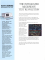
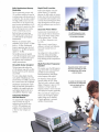
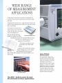
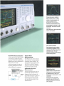
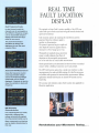
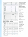
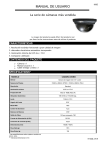
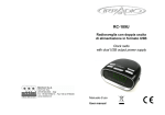
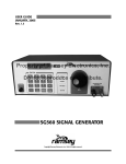
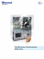
Marconi Instruments T h e M i c r o w a v e Test R e v o l u t i o n 6 2 0 0 series 6200 SERIES MICROWAVE TEST SET THE INTEGRATED MICROWAVE TEST REVOLUTION T h e M T S is t h e economical test solution that is faster a n d easier t o use than t h e multitude of individual i n s t r u m e n t s usually associated with microwave m e a s u r e m e n t s . Its high accuracy ensures that t h e M T S is equally applicable for design, m a n u f a c t u r e a n d m a i n t e n a n c e tasks. Field applications include c o m m i s s i o n i n g and repair of microwave radio links, radar a n d electronic warfare systems. The MTS — Microwave Test Set — revolutionizes microwave bench and field measurements. A complete set of instrumentation covering 10 MHz to 26.5 GHz is integrated into one compact and portable package. Using t h e p r o g r a m m a b l e voltage/current source, swept or static analysis of c o m p o n e n t s a n d s u b - s y s t e m s is available. This o p e n s u p a wide variety of n e w applications. Intelligent markers, a u t o m a t i c pass/fail analysis, The main elements of the MTS are a synthesized sweep generator, a scalar analyzer, a power meter, a frequency counter and voltage/current source. A clear color display gives high definition readout of swept responses and digital readings of power and frequency. A major additional facility is real-time Fault Location. It gives the precise position of faults and discontinuities in coaxial and waveguide antenna feeders. The MTS is the ideal solution for development, production, installation, commissioning and maintenance tasks. Just one instrument replaces all the individual instruments currently required. But the MTS is much more than a collection of discrete instruments - it is a fully integrated test system designed to simplify numerous microwave measurement problems. a m e m o r y card for saving settings a n d traces a n d a M a c r o function to store a n d replay key-press s e q u e n c e s further extend t h e m e a s u r e m e n t capabilities. A n intuitive user-interface ensures quick learning, fast operation a n d ease of use. H a r d keys access a r a n g e of soft key functions. T h e u s e r is p r o m p t e d to m a k e t h e required selections a n d help m e s s a g e s are used to guide a n d assist. T w o versions of t h e M T S are available, b o t h covering a c o n t i n u o u s wide frequency r a n g e . 6200 covers 10 M H z to 20 G H z , 6203 covers 10 M H z to 26.5 G H z . Fully Synthesized Generator Sweep Rapid Fault Location Fault location displays return loss The fast synthesized generator with against distance. It is especially 1 Hz resolution combines the speed of important for field analysis of antenna an analog sweeper with the precision of feeders since faults and discontinuities a synthesizer. Fast step times coupled in coaxial cables and waveguides can be with high stability ensures that even accurately located and diagnosed. Short narrow filters can be measured with range discontinuities and faults spaced speed, accuracy and confidence. A 400 only a few millimetres apart can also be point sweep can be m a d e in less than resolved. 200 ms allowing interactive tuning without compromising accuracy. Accurate Power Meter Accurate power measurements are Both start/stop and center/span sweep modes may be used as well as a CW mode for spot frequency measurements. made using the Marconi Instruments range of nine Power Sensors. Power The MTS integrates measurement many functions one portable in package. can be measured from - 7 0 dBm to +35 dBm at frequencies up to With the step attenuator option, amplitudes can be set from + 2 0 dBm down to - 9 0 dBm. Fundamental frequency generation gives low level harmonics ( < - 4 0 dBc) and spurious 26.5 GHz. High accuracy is assured since a calibrator is included and Calibration Factor and Linearity Factor are corrected. signals ( < - 6 0 dBc). An analog meter is also provided to The levelled accuracy of typically <±0.5 dB and superior source match means that a second detector to give a live reference may be omitted to assist when tuning and peaking. Maximum and minimum hold and limit-checking provides comprehensive analysis. simplify measurements. Versatile Scalar Analyzer The four input scalar analyzer has a 90 dB dynamic range with excellent linearity. Both AC and DC detection are provided. Two auto-scaling display channels, each capable of displaying up to two measurements are available. Up to four live or stored traces can be displayed. Simultaneous measurement of passband and stop-band characteristics is available in un-coupled mode since each display channel can be set to Multi-Function Counter Frequency Separate range of the MTS. Limit checking is be omitted from ATE saving provided for fault monitoring. source increases the range of applications so that devices such as VCOs, PIN modulators and amplifiers can be characterized at fixed or swept voltages and currents. counters cost and can now space. M a x i m u m / m i n i m u m hold display assists frequency drift analysis. The frequency counter has two functions within the MTS. W h e n A variety of microwave 'Read-out' mode is selected a digital instruments display of frequency is given to 1 Hz resolution. In 'Swept' mode the frequency counter is used to read and then display the frequency graphically. When used with the voltage/current The programmable voltage/current and frequency sweep different frequency ranges. Integrated Voltage/ Current Source power meters The counter covers the full frequency source a plot of frequency against applied voltage can be obtained, a typical application is automatic oscillator characterization. are test integrated into one simple to use compact unit. WIDE RANGE OF MEASUREMENT APPLICATIONS A wide r a n g e of m e a s u r e m e n t functions a r e incorporated into the M T S t o m a k e n u m e r o u s sophisticated m e a s u r e m e n t s rapidly and simply. Integrating all t h e functions into a single i n s t r u m e n t eliminates t h e n e e d for system interconnections, avoids s e t - u p errors a n d provides faster m e a s u r e m e n t s . T h e m e m o r y card extends t h e o n board m e m o r y t o store i n s t r u m e n t settings with limit lines, m e a s u r e m e n t traces a n d calibration data. Both plot a n d print h a r d copy Convenient Memory Card facilities a r e available. A n y H P G L compatible plotter can b e driven from the GPIB port and any E p s o n FX series compatible printer c a n b e c o n n e c t e d t o t h e parallel port. Both o u t p u t s are buffered so that m e a s u r e m e n t s c a n c o n t i n u e while plotting. A s e q u e n c e of key strokes a n d c o m m a n d Versatile Hard Copy strings, including pauses, c a n b e entered and automatically executed using t h e M a c r o facility. M a c r o p r o g r a m s c a n b e stored internally o r o n a Unique PIN Diode Characterization m e m o r y card. The programmable voltage/current port allows automatic analysis of PIN switches and attenuators. The applied voltage can be changed so that a plot of attenuation versus voltage is obtained. Insertion loss can be simply displayed for a range of bias voltages. Multi-Port Device Analysis Four scalar analyzer detector inputs simplify the adjustment and tuning of multi-port devices such as circulators, directional couplers and diplexers. User Defined Macro The MTS — built-in power to meet the demands of future applications Comprehensive Analysis Eight markers plus a 'delta marker' assist analysis reduce reading Automatic and errors. search such as minimum and maximum find, are provided 'N-dB bandwidth' as well as and peak-to-peak response. Limit lines give rapid 'go/no-go' automatic testing. Dual Channel Dual channel Mode mode enables two different displays of the response of a filter to be simultaneously. response and pass-band can be clearly A swept voltage from the MTS is applied Simple Mixer Measurements to the Voltage Controlled Oscillator. T h e GPIB port can control a second Fast VCO Characterization Frequency and level are simultaneously MTS synthesized sweep generator for displayed on two axes to characterize the synchronous mixer evaluation. T h e device quickly and simply. two synthesizers sweep together with a A VCO can therefore be easily and accurately characterized in seconds without additional test equipment. 6200 Microwave Test Set Voltage Detector Sweep ripple seen. fixed offset to enable the frequency response of a mixer and its IF filter to be rapidly and simply measured. Automatic Two Measurement Port Digital Read Out Digital read out of power An output signal generated at the end of each sweep is used to activate a Frequency counter shown Overall changeover switch to alternate the swept signal between the two ports of frequency increase of applications Frequency the of the and range MTS. is measured to 1 Hz resolution. devices such as isolators. The dual VCO channel display can simultaneously Automatic show the full characteristics of n o n - against user-set reciprocal devices. Maximum/Minimum drift limit analysis. checking limits and Hold aid REAL TIME FAULT LOCATION DISPLAY Dual Frequency Scales In dual channel mode the channels can be uncoupled so that different frequency ranges can be sequentially swept to display pass-band and stopband on one screen. This powerful technique simplifies the design and alignment of even the most complex filters. T h e optional real time Fault Location capability of t h e M T S n o w m a k e s field repair of b o t h coaxial and waveguide a n t e n n a feeders b o t h quick a n d economical. Fault Location operates by analyzing t h e interference patterns generated w h e n t h e reference signal is incident o n discontinuities. T h e pattern is processed to give a rapid a n d clear display of return loss against distance. Accuracy is 0.1 % of range u p to 1 k m . W a v e g u i d e s are analyzed using a non-linear sweep to totally eliminate t h e effects of dispersion s o that w a v e g u i d e m e a s u r e m e n t s are as fast a n d clear as coaxial cable m e a s u r e m e n t s . Closely spaced faults can b e d e t e r m i n e d so that even loose or corroded contacts within a bulkhead c o n n e c t i o n can be pin-pointed. Automatic VCO Measurement Using the frequency counter and programmable voltage source the frequency/voltage relationship can be simply displayed. A detector is used to show the variation in level with frequency. T h e M T S fault location option h a s a simple user-interface to allow m e a s u r e m e n t s to b e m a d e with little training. It is ideal for microwave and cellular radio operators for a n t e n n a feeder m e a s u r e m e n t s . Military applications include fault location o n aircraft E W systems a n d o n board ship. T h e accuracy a n d resolution m a k e s Fault Location also applicable to laboratory applications. PIN Attenuator Characteriza tion Four measurements are made, each with a different bias voltage automatically applied from the programmable source. Many components and devices can be simply characterized in this way. Revolutionize your Microwave Testing... TECHNICAL SPECIFICATION SYNTHESIZED GENERATOR SWEEP Frequency Range 6200: 10 MHz to 20 GHz. 6203: 10 MHz to 26.5 GHz. Resolution 1 Hz. CW Accuracy Frequency standard accuracy ±0.5 Hz. Typical Swept Accuracy Step time 250 us lms 10 ms Frequency Up to 2 GHz > 2 GHz <5kHz < 100 kHz < 500 Hz < 1.5 kHz < 50 Hz < 50 Hz Power 6200/6203 standard. Frequency range (GHz) 0.01 to 2 2to8 8 to 18 18 to 20 20 to 26.5 Power-levelled (dBm) Guaranteed Maximum typical -10 to+7 +11 —10 to +6 + 1 0 -10 to+5 +10 -10 to+5 +8 -10 to+4 +8 6200 + opt 001 (step attenuator) Power-levelled (dBm) Frequency Guaranteed Maximum range (GHz) typical 0.01 to 2 -80 to+5 +9 2 to 8 -80 to+4 +8 8 to 18 -80 to+3 +7 18 to 20 - 8 0 to +2 + 5 For option 002 (Field replaceable RF connector) guaranteed output is reduced by 0.5 dB. Settable power ranges Standard: - 2 0 dBm to +20 dBm. With Option 001: - 9 0 dBm to +20 dBm. Resolution 0.01 dB. Levelling Accuracy (including flatness at 0 dBm). Standard and Option 002 ±1 dB, ±0.5 dB typical. Linearity: < 0 . 5 dB over guaranteed power range. Option 001 (including Option 002 if fitted) 10 MHz to 8 GHz: ±1 dB ±0.3 dB ±2% of attenuator setting in dB 8 GHz to 20 GHz: ±ldB(±ldBor ±4% of attenuator setting in dB, whichever is greater). Levelling Via rear panel BNC input socket. Accepts signals from a detector (positive or negative) or from the analog output of a power meter (0 to ± 1V). Accuracy depends on levelling technique. Power Stability Temperature with With option 001 minimum return loss specification degrades by up to 5 dB. With option 002 minimum return loss specification degrades by up to 3 dB. Volts/GHz Voltage proportional to frequency available from rear panel BNC Voltage/Current output. Typical values following power calibration at operating temperature. Self-calibration with a Power Sensor removes temperature effects. Range: 1 V or 0.5 V/GHz selectable (20 V maximum in 1 V/GHz mode). Linearity: ±15 mV. 6200 0 to 20°C 20 to 40°C 40 to 50°C <0.02 dB/°C < 0 . 0 4 dB/°C < 0 . 0 8 dB/°C PROGRAMMABLE VOLTAGE/CURRENT SOURCE 6203 0to20°C 20 to 30°C 30 to 50°C <0.1dB/°C < 0 . 0 8 dB/°C <0.06 dB/°C Range: - 1 5 V to +15 V Resolution: 1 mV Accuracy: ±15 mV Signal Voltage Sub-harmonics and spurious signals < - 6 0 dBc. There are no sub-harmonics for frequencies above 2 GHz. Phase noise Typical values measured in 1 Hz bandwidth at 20 kHz offset from the carrier in CW mode. 0.01 to 2 GHz <-90dBc/Hz 2 to 8 GHz <-78dBc/Hz 8 to 12 GHz <-74dBc/Hz 12 to 20 GHz <-70dBc/Hz 20 to 26.5 GHz <-67dBc/Hz Residual FM In 100 kHz bandwidth in CW mode: 0.01 to 2 GHz < 1 kHz peak 2 to 26.5 GHz < (500F) Hz peak where F is the frequency in GHz. Connector Type 6200: Precision N (female), 50 Q . 6203: MPC (Marconi Precision Connector) 3.5 mm (female), 50 Q . Option 002: Field replaceable, 50 Q precision 3.5 m m (female) and N-type (female). Reverse input power 100 mW maximum. Current Output Range: - 1 5 0 mA to +150 mA Resolution: 10 u,A Accuracy: ±300 uA Total power supplied not to exceed 1.25 W. Output Connector Rear panel BNC. SCALAR ANALYZER Number of Inputs Four (A, B, C and D). Detection Modes AC and DC. Dynamic Range AC detection: 85 dB ( - 6 5 to +20 dBm), 90 dB typical ( - 7 0 to +20 dBm) DC detection: 80 dB ( - 6 0 to +20 dBm) Number of Points Number of Channels Two, two measurements may be made per channel allowing a total of four simultaneous measurements. Sweep Time Settable range 40 ms to 500 s, automatically selected or manually entered. Measurement times 401 points: 1601 points: < 2 0 0 ms. < 8 0 0 ms. Direct Voltage Input Input A, B and C Input D Source Match (internally levelled) Noise Averaging Return Loss (dB) Typical Minimum >17 >15 >33 >26 >30 >21 >25 >16.5 >20 >15 Measurement User selectable from 2 to 1601. Frequency range (GHz) 0.01 to 0.05 0.05 to 2 2 to 8 8 to 12 12 to 26.5 VSWR <1.45:1 <1.11:1 <1.2:1 <1.35:1 <1.45:1 Output Total power supplied not to exceed 2.5 W. Purity Harmonics 0.01 GHz to 2 GHz < - 2 7 dBc, - 3 5 dBc typical. 2 GHz to 8 GHz < - 3 5 dBc, - 4 0 dBc typical. 8 GHz to 26.5 GHz < - 4 0 d B c , - 5 0 dBc typical. Output Power Sweep range From maximum levelled power Standard: > 2 5 dB With Option 001 : > 9 5 dB Internal External Range 0 to - 4 . 5 volts 0 t o - 9 volts Reduction 1 td 1000 (applied per measurement). Smoothing Aperture settable from 0.01 to 20% of span, resolution 0.01% Calibration Path calibration (Normalization) types Through, short/open, short. Instrumentation Accuracy Uncertainty ±0.05% System ±0.7% Accuracy Refer to individual specifications for detectors and Return Loss Bridges. FAULT LOCATION (optional) Distance Units Metres or feet. Accuracy 0.1% of range or 3 mm, whichever is the larger (for a single fault up to 1 km range). Full scale Up to 25 km depending on cable or waveguide loss. Minimum resolution For two equal amplitude discontinuities using maximum sweep width. 6200: 1.82 cm. 6203: 1.37 cm. These resolution values are for a relative velocity (V ) of 1. For other velocities the minimum distance resolution is:6200: 1.82 X V cm. 6203: 1.37 X V cm. r r r Dynamic Range Time Normal mode: < 2 5 0 ms. Enhanced mode: < 5 0 0 ms. Number of Points AM Accuracy ±1.2% worst case for one year. Auto-Zero Set Removes DC offset from signal input. 6910 Series: ±100 nW. 6920 Series: ±50 pW. 6930 Series: ±3 uAV. Drift 6910 Series: ±10 nW. 6920 Series: ±50 pW. 6930 Series: ±300 nW. Noise 6910 Series: ±100 nW. 6920 Series: ±50 pW. 6930 Series: ±3 u.W. Response Time < 1 0 0 ms. Averaging 1 to 1000 selected automatically or manually entered. Chart Recorder Rear panel voltage/current BNC output gives a voltage proportional to measured power. Sensitivity 0 to 5 V: 0 V level dependent upon type of detector or sensor used. • AC detection: 80 dB. DC detection: 70 dB. Measurement (401 Points) traceable to National Standards. Measurement User selectable from 51 to 512. POWER METER Frequency Range Log mode: 1 V per decade. Linear mode: Scaling dependent on detector or sensor. FREQUENCY FREQUENCY Resolution 1 Hz Accuracy Power Readout mode Range COUNTER RANGE 6200: 10 MHz to 20 GHz. 6203: 10 MHz to 26.5 GHz. 30 kHz to 26.5 GHz, dependent upon sensor used. - 7 0 dBm (100 pW) to +35 dBm (3 W), dependent upon sensor used. Swept mode 1.5 MHz peak to peak at 75 Hz to 10 MHz rate. Tolerance Up to 40% modulation depth for signals within the range of sensitivity and maximum input level. Acquisition Time Readout mode Typically 2 s for frequencies greater than 300 MHz. Swept mode Typically 50 ms per point. Selectivity Typically 25 dB. DISPLAY Type Color display with 15 cm (6 inch) visible diagonal. External color monitor output available on rear panel. Number of Channels Two. A channel may be configured either as a swept channel for displaying traces or a readout channel for displaying read-outs of values such as power and frequency. Number of Traces/Read-Outs Four. Maximum of two per channel. Titles Screen title plus individual measurement titles. Swept Channel Characteristics The horizontal and vertical axes can be configured to display a variety of different measurements. The horizontal axes, referred to as 'Domain', may be defined to display the stimulus such as frequency, power, voltage, current and distance. The vertical axis, referred to as 'response', may display frequency, power and voltage. Domain (Horizontal axis) Frequency Modes: CW, start/stop, center/span, alternate sweep. ± 1 Hz ± frequency standard error. Frequency Resolution: Swept mode Settable to 1 Hz, displayed as six digits. 0.05% ±100 Hz ± frequency standard error. Frequency Offset: Frequency offset between source and display can be entered to characterize frequency changing devices such as mixers. Frequency Scaling: Multiplication factor between source and display can be entered to characterize frequency multipliers and dividers. Instrumentation Accuracy Correction Sensitivity Calibration Factor Range: 0.01 to 200%. Resolution: 0.01. 10 MHz to 10 GHz 10 GHz to 20 GHz 20 GHz to 26.5 GHz Linearity Factor Range: 0.1 to 15. Resolution: 0.1. Maximum Input Power +27 dBm peak. Reference < - 2 0 dBm typical. < - 1 5 dBm typical. < - 1 0 dBm typical. Level + 5 dBm. Damage Level Used for Power Sensor correction. Input Output Connector N (female), 50 Q . Adapters are supplied with 75 £2 and MPC (Marconi Precision Connector) 3.5 mm Power Sensors. Type 6200: Precision N Type (female). 6203: MPC (Marconi Precision Connector) 3.5 m m (female). Connector Input impedance Frequency 50 ft. 50 MHz ±0.01 Level 1 m l MHz. FM Tolerance Readout mode 20 MHz peak to peak at 45 Hz to 10 MHz rate. Power Sweep Range Range depends on option - refer to Synthesized Sweep Generator section. Power Offset Power offset between source and display can be entered for use when measuring amplifiers and attenuators. Response (Vertical axis) Units dBm, dB, pW to kW, nV to V, VSWR, Hz to GHz. Scaling Manual auto-scale (single shot), continuous auto-scale (every sweep) or user selectable. Reference level position Reference level may be set to any graticule line. Reference level value -199.99 to +199.99 all units except VSWR. 1 to 100 VSWR. Measurement Manipulation Scalar detector and counter inputs Display live measurement. Display trace memory. Display live measurement relative to trace memory. Measurement hold may be applied for each trace. Scalar detector inputs only Any input or ratio of inputs may be assigned to any one or more than one of the traces. A trace may display absolute power, power relative to a path calibration or power minus a trace memory. Limit checking: Upper and lower test limits may be entered. Relative measurement: To display the measured offset from a previously entered measured reading. Max/Min hold: To display maximum and minimum values over a period of time for drift measurements. Ageing: Better than ±2 in 10 per year. Input Offsets: An offset in the range -99.99 to +99.99 dB in 0.01 dB steps may be applied per detector or sensor input. AUXILIARY INPUTS AND OUTPUTS GPIB Interface Memory Card Interface For external storage of data and installation of software options. Parallel Printer Power: 0.01 dB. Current: 10 pA. Frequency: Six digits. 1 or 10 MHz input or 10 MHz output selectable from front panel. Voltage: 1 nV. External Marker functions Marker, delta marker, minimum, maximum, search left, search right, N-dB bandwidth (with centre frequency). Peak to peak response value and optional test against limit. Levelling Input BNC For connection of remote detector or power meter for source levelling. Voltage/Current Output BNC Power: Four digits. External Measurement Monitor Output to a variable scan rate color monitor such as NEC Multisync™ (rear panel 15 way 'high density' D type female). Manipulation The following facilities are available: Marker readout: Spot readings may be made at the domain value specified by the active marker. Settings stores: 10. Power sensor cal stores Stores for 10 sets of Power Sensor calibration and linearity factor data. Memory card Extra stores available on memory card. Real Time Clock Date and time. Used to date-stamp hard copies and to determine instrument operating hours. Radio Frequency Interference Conforms with the requirement of EEC Directive 76/889 as to limits of RF interference. Safety Rated Range of Use (over which full specification is met) Temperature: 0 to 50°C. of Storage Horizontal sync frequency: 24.77 kHz nominal. Vertical sync frequency: 54.9 Hz nominal. Horizontal sync width: 3.5 ps nominal. Vertical sync width: 204 \is nominal. and Temperature: - 4 0 to +70°C. Humidity 9 3 % RH at 40°C. Power Requirements Switchable voltage ranges 115 V set: 90 to 132 V 230 V set: 188 to 265 V Dimensions Chart recorder: Voltage proportional to power level of scalar detector or power meter sensor input. Frequency: Hz to GHz. Standard Trace memories: Four. Fixed: Fixed voltage or current output for bias measurements. Readout Channel Characteristics Resolution Power: dBm, dB, pW to kW. Memories AC Supply Swept V/I: Swept voltage or current for voltage/current domain measurements. Units External 1 or 10 MHz standard rear panel BNC input socket. User definable to be: Volts/GHz: Voltage proportional to frequency output from source. Input Offsets: An offset in the range -99.99 to +99.99 dB in 0.01 dB steps may be applied per detector input. Frequency: 1 Hz. 7 Conditions Transport Frequency Standard In/Out BNC Response (Vertical) Power: 0.01 dB. Temperature stability: Better than ±0.15 ppm/°C. Complies with IEC 348. Output Compatible with any Epson FX series printer. Output is buffered to allow further measurements whilst printing. Voltage: 1 mV. Internal Peaking Meter Display: Analog display to assist when adjusting power levels. Marker Resolution Standard For synthesized sweep generator and frequency counter. 30 MHz VCXO. Markers Eight per channel plus a separate delta marker. Domain (Horizontal) Frequency: Six digits with over-ride to give 1 Hz resolution. Frequency Duty Cycle: To display peak power given by average power measured/duty cycle. Range: 0.001 to 100%. GPIB is IEEE 488.1 and 488.2 compatible. The interface has three applications:- Instrument control with full talk and listen. - Control of a plotter using HPGL. Plotter output is buffered to permit measure ments to proceed whilst plotting. - Control of a second MTS for mixer measurements. The instruments may be set to sweep with a fixed frequency offset between them. Complex limit lines Four stores of 12 segments each. Each segment defines an upper and a lower limit line or point. Any store can be applied to any trace. GENERAL SPECIFICATION 45 to 440 Hz. 500 VA maximum. Height 197 mm 7.75 in Weight 6200 6203 and Weight Width 389 mm 15.3 in Depth 546 mm 21.5 in 19 kg 41.71b 19.5 kg 42.8 lb 4 Notes: Guaranteed Power Range Power Accuracy and VSWR are calibrated for the temperature range 0 to 50°C and are subject to the availability of National Standards. Typical performance figures are nonwarranted. 6230 SERIES SCALAR DETECTORS Test Heads for Fault 6230 Frequency range (GHz) 0.01 to 20 Dynamic range (dBm) -70 to+20 - 7 0 to +20 Maximum RF +26 CW +26 CW input (dBm) +30 peak +30 peak 0.01 to 26.5 VSWR 10 MHz to 40 MHz 1.4:1 1.4:1 40 MHz to 100 MHz 1.15:1 1.15:1 100 MHz to 2 GHz 1.12:1 1.12:1 2 GHz to 5 GHz 1.17:1 1.17:1 5 GHz to 18 GHz 1.29:1 1.29:1 18 GHz to 20 GHz 1.5:1 1.5:1 20 GHz to 26.5 GHz - 1.5:1 10 MHz to 8 GHz 8 GHz to 18 GHz ±0.5 ±0.65 ±0.5 ±0.65 18 GHz to 20 GHz ±1.25 ±1.25 20 GHz to 26.5 GHz - ±1.25 Connector Precision Precision Type N male MPC 3.5 mm male Length (mm) 79 79 Width (mm) 27 27 Weight (g) 250 250 Power Accuracy (dB) AC DC - 6 0 dBm 1.2 - Directivity'' - 5 0 dBm 0.7 0.9 38 dB, 10 MHz to 18 GHz. - 4 0 dBm 0.4 0.45 - 3 0 dBm 0.4 0.4 - 2 0 dBm 0.35 0.35 - 1 0 dBm 0.3 0.3 OdBm 0.2 0.2 + 10 dBm 0.3 0.3 + 16 dBm + 16 to +20 dBm 0.4 1.0 (typical) 0.4 1.0 (typical) Test Head 6581 & 6581E Frequency Range 10 MHz to 20 GHz, limited to IS GHz for return loss measurement. Input port connector Precision Type N female. Frequency Response (dB) Fault location test port Connector. Precision Type N female. Return loss > 2 0 dB, 10 MHz to 10 GHz. > 1 5 dB, 10 to 18 GHz. Return loss port"" Connector. 6230/6233 Precision Type N female. 1 Size (excluding connectors) 178 x 117 x 45 mm. Detector cable length 1.5 metres. Test Head 6583 & 6583E Note: Specification applies at 50 MHz at a temperature of 22°C ± 5°C and does not include errors due to mismatch, harmonics and temperature. Performance above +16 dBm is typical non-warranted. Different specifications are given Frequency range 10 MHz to 26.5 GHz. for detectors when using AC or DC detection. RETURN LOSS BRIDGES - Input port connector Precision 3.5 mm female. AUTOTESTERS A range of Return Loss Bridges are available for the precise determination of Return Loss over a wide frequency range. Model/ 59999-151W 59999-15BR 59999-f59B 5 9 9 9 9 - 1S2D 59999-16SH 0.01-18 0.01-I8 0.01-18 0.01-26.5 0.01-26.5 Fault location test port Connector. Precision 3.5 mm female. Characteristic Return loss Frequency range (GHz) Directivity (dB) 0.01-18 GHz 18-26.5 GHz 40 38 N/A N/A Frequency sensitivity (dB) ±1.2 ±1.5 38 38 38 N/A 35 35 ±1.5 ±2.0 ±2.0 > 2 0 dB, 10 MHz to 10 GHz. > 1 5 dB, 10 to 18 GHz. > 1 2 dB, 18 to 26.5 GHz. 1 Return loss port' " Connector. WSMA female. 1 Accuracy 0.01-8 GHz 0.010 ± 0.06p 8-lSGHz 0.010 ± O.lOp 0.013+ 0.I2D N/A N/A N/A O.OI8 + O.I2p 6.5 6.5 6.5 6.5 2 2 18-26.5 GHz 2 Insertion loss (dB) 0.013 ± 0.08p-' 2 2 0.013 ± O.lOp 2 0.0l3±0.l0p 0.013 ±0.08p 0.013+ O.I2p 2 0.013 ± O.lOp 2 0.013 + O.lOp 2 2 0.018 ±0.12p 2 2 6.5 Max. input power (dBm) Test port connector Input connector 3 Length (mm) Width'(mm) 3 Depth (mm) Weight (g) 1 +27 +27 +27 +27 +27 GPC-7 N(m) N(f) WSMA(m) WSMA(f) N(D N(f) N(f) Ruggcdized k(l) Ruggedized k(f) 76 76 76 54 54 50 50 50 38 38 28 28 28 I9 19 340 340 340 I98 198 Where p — measured reflection coefficient - includes directivity and test port reflection effects over the specified frequency range. 2 Nominal value from input port to test port. 3 Excluding connectors and cable. Location 6581 and 6583 series of Test Heads interface the MTS to the device under test when Fault Location is used. The ' - 0 0 1 ' version Transmission Line Test Heads incorporate a Return Loss Bridge. The economy 'E' or '—002' version Fault Location Test Heads omit the Bridge. 6233 Directivity^" 38 dB, 10 MHz to 18 GHz. 35 dB, 18 to 26.5 GHz. Size (excluding connectors) 160 x 110 X 45 mm. Detector cable length 1.5 metres. :: "Not applicable to 'E' versions. VERSIONS Ordering numbers 6200 6203 Option Option 10 MHz to 20 GHz Microwave Test Set 10 MHz to 26.5 GHz Microwave Test Set 001 002 70 dB step attenuator (available for 6200 only) Scalar Analyzer Field Replaceable RF output connector (3.5 mm and N-type) For Fault Location order 59000- 180F Fault Location Software Card SUPPLIED Linearity is automatically corrected with the 6230 series self-identifying detectors. The 6230 is used for measurements to 20 GHz; 6233 covers up to 26.5 GHz. ACCESSORIES AC Supply Lead 43123-076 2 m Power Sensor Cable 06950-081\V Operating Manual Input socket cap 6950-069 OPTIONAL ACCESSORIES 6230 6233 6230 Series Scalar Detectors 10 MHz to 20 GHz, N type (m) 10 MHz to 26.5 GHz, MPC (Marconi Precision Connector) 3.5 mm (m) 5691056911569125691356919- Power Meter Sensors 6910 Series ( - 3 0 dBm to +20 dBm) 10 MHz to 20 GHz, N type (m) 10 MHz to 20 GHz, APC 7 30 kHz to 4.2 GHz, N type (m) 10 MHz to 26.5 GHz, MPC (Marconi Precision Connector) 3.5 mm (m) 30 kHz to 3 GHz, N type 75 fi 900L 900X 900U 900D 900Y 56920- 900J S6923-900T Detectors 6920 Series ( - 7 0 dBm to - 2 0 dBm) 10 MHz to 20 GHz, N type (m) 10 MHz to 26.5 GHz, MPC (Marconi Precision Connector) 3.5 mm (m) 56930-900F 56932-900N 6930 Series ( - 1 5 dBm to +35 dBm) 10 MHz to 18 GHz, N type (m) 30 kHz to 4.2 GHz, N type (m) 56581-001T 56583-001S Transmission Line Test Heads (includes Software Card) 20 GHz Transmission Line Test Head, 6581 26.5 GHz Transmission Line Test Head, 6583 56581-002P 56583-002W265 Fault Location Test Heads (includes Software Card) 20 GHz Fault Location Test Head, 6581E GHz Fault Location Test Head, 6583E 06950—086M 06950-087C 06950-Q88R 03964-325P 54311—111E 54311-113Y 54311—112U 54311—118G 54311—120F Sensor/Detector Cables 5 m Power Sensor Cable 15 m Power Sensor Cable 50 m Power Sensor Cable 5 m Detector Extension Cable 15 m Detector Extension Cable 25 m Detector Extension Cable Direct Voltage Measurement Cable 1.5 m Extension Cable for Transmission Line Test Head 1.5 m Extension Cable for Fault Location Test Head 43129-189U 43126-012S 46884-560M Miscellaneous Electrical GPIB Cable 50 Q. BNC(m) to BNC(m) 1.5 m Parallel Printer Interface Cable Fault Fault Location Power Meter Sensors A range of nine power sensors cover 30 kHz to 26.5 GHz for the measurement of power from -70 dBm (100 pW) to +35 dBm (3 W) with a range of connector types. Location Cables Return Loss Bridges Return Loss Bridges or 'Autotesters' are available for the swept measurement of return loss. Microwave Cables 54311—109U Ruggedized Cable N(m) to N(m) 3 m (for Fault Location) 54311—110H Ruggedized Cable 3.5 mm (m) to 3.5 mm (m) 3 m (for Fault Location) 54311—116J Ruggedized Cable N(m) to N(m) I.5 m (for Fault Location) 54311—117F Ruggedized Cable 3.5 mm (m) to 3.5 mm (m) 1.5 m (for Fault Location) 5 4 3 5 I - 0 2 2 X Cable N(m) to N(m) 0.5 m 54351-025R Cable 3.5 mm (m) to 3.5 mm (m) 0.5 m 59999-151W 59999-158R 59999-159B 59999-152D 59999-166H Autotesters 10 MHz to I8 GHz 7 mm 10 MHz to IS GHz N(m) 10 MHz to 18 GHz N(f) 10 MHz to 26.5 GHz WSMA (in) 10 MHz to 26.5 GHz WSMA (0 54311-123S 54311-124W Power Splitters Power splitter DC to 18 GHz Type N Power splitter DC to 26.5 GHz 3 i mm 59000-181G 59000-182V 54127-309Z 54124—027S 59000—180F 54121-034F 46882-112C Miscellaneous 32k Blank Memory Card 128k Blank memory card Rack Mount Kit Front Stowage Cover Fault Location Software Card Detector Input Socket Cap Service Manual Transmission Line and Fault Location Test Heads Transmission line test heads provide a rapid and convenient interface for fault location measurements. Marconi a r c o m Instruments UK Marconi Instruments Ltd Longacres St Albans Herts, England AL4 OJH Tel: (+44) 727 59292 Fax: (+44) 727 57481 Tlx: 23350 MAIICON G Primed in [he UK 69283-C-RP USA Marconi Instruments Inc. 3 Pearl Court Allendale Hew Jersey 07401 Tel: 201 934 9050 Toll Free: 1 800 233 2955 Fax: 201 934 9229 France Marconi Instruments S.A. 18 rue du Plessis-Briard le Canal Courcouronnes 91023 Evry Cedex Tel: (1) 60 77 90 66 Fax: (1)60 77 69 22 Tlx: 604 482 Germany Marconi Messlechnik GmbH Landsberger Strasse 65 8034 Germering Tel: 089 84936 0 Fax: 089 8419142 Tlx: 5212642 MMMC D Netherlands Marconi Inslrumenten Van Limburg Stirumlaan 4 5037 SK Tilbutg Poslbus 645 5000 AP Tilbutg Tel: 013 63 95 40 Fax: 013 63 96 63 Spain Marconi Instrumentos S.A. Calle de Gobelas 13 Urbanization "La Florida" 28023 Madrid Tel: 372 98.75 Fax: 307 69 39 Tlx: 57481 MIES E As we arc always seeking to improve our products, the infonnation in this document gives only genera! indications of product capacity, performance and suitability, none of which shall form pan of any contract. Holding Company: The General Electric Company pic of England. ©Marconi Instruments Limited 1991. Hong Kong Marconi Instruments Ltd Rm 702-3 CC Wu Building 302-308 Hennessy Road Wanchai Tel: 8327988 Fax: 8345364 Tlx: 72369 MINST HX Australia Marconi Instruments (Ply) Limited RO. Box 1390 Level 4 15 Orion Road Lane Cove H.S.W. 2066 Tel: (02) 418 6044 Fax: (02) 418 6383 Issue 1 12/91 46S89-M