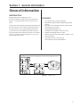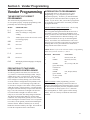
1
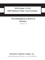
ESDI Model 110100
MDB Multiprice Water Vend Controller
PROGRAMMING & SERVICE
MANUAL
(November 18, 2011)
Electronic Systems Design, Inc.
1010 North Maclay Avenue, San Fernando, CA 91340 USA www.esdi.net
Section 1. General Information
General Information
INTRODUCTION
Programming is done “Menu Style” with
the menus consisting of “Main Items” and “Sub-Items.”
Figure 1.1 is a good example of how the menu system
works.
FEATURES
•
•
“Cash” is the first menu after pressing the mode button on
the control board. You can only access menu items from
the menu you are in. Just as the “ENTER” button takes
you into each level, the “HOME” button takes you back
to previous menu levels each time you press it. The menu
system is explained in greater detail in Section 4. Vender
Programming: Menu Levels.
•
•
•
•
•
1st Level
User-friendly menu style programming.
Hand Held Computer (HHC) programming and data
retrieval.
Real time clock / calendar to control “built-in” timer
(can display time on LED).
Supports Multi-Drop Bus coin
mechanisms, bill validators, and card readers.
Capable of setting full escrow to vend.
Both total (historical) and individual (resettable) vend
and cash counters.
Can display the sale (vend) and cash
totals (historical) on the LED DISPLAY.
2nd Level
3rd Level
up
down
enter
enter
home
home
up
up
down
down
Figure 1.1. Menu levels.
2
Section 2. Vender Component Explanation
Vender Component
Explanation
OPERATION REQUIREMENTS: The control board
requires approximately 24 volts AC from the low voltage
transformer (described later in this section). This will
allow the control board to function and to supply power to
all the vender’s components listed below.
OPERATION: Upon receiving the appropriate voltage
from the transformer, the control board will issue
information to some components, receive information
from some components, and communicate both ways with
some components.
•
•
•
The control board issues instructions (and / or
voltage) to:
LED display
Vend board
.
.
The control board receives information (and / or
voltage) from:
Select switches (logic level)
Program switch (logic level)
Vend sensor
Temperature sensor (for use with electronic
refrigeration control)
The control board communicates both ways with:
Coin mechanism
Bill validator (optional)
Debit card reader (optional)
Hand Held Computer (optional)
3
Section 2. Vender Component Explanation
Connect MDB Cable Here
Coin Mech, Bill Acceptor, etc.
P3
Expansion Connector
P8
P9 OPTION SWITCHES P4 Drop Sensor
P15
P12
P7
P14
SELECTION SWITCHES
MODE
Connect Select Switches Here
P1 DISPLAY
P10 DEX 2
P11 DEX 1
Connect DEX Terminal Here
Connect Display Cable Here
Figure 2.1.
Back Side of ESDI Model 110100
CONTROL BOARD
Standard LED Display Interface (Position P1 ): The four
(4) wire harnesses connecting to this pinout travel from
the vender’s LED to the control board. It allows the
control board to send power to and communicate with
the LED. If this harness is cut or disconnected, the LED
will go blank. If this harness is pinched, you may see
“broken segments” on the LED with various segments of
the display lit.
PIN
NUMBER
1
2
3
4
WIRE
COLOR
YELLOW
GREEN
BROWN
RED
FUNCTION
5 VDC POWER
DISPLAY CLOCK
DISPLAY DATA
DISPLAY 5 VDC
RETURN TO COMMON
4
Multi-Drop Bus ( Position P3 ): The f ve (5) wire serial
harness connecting to this pinout provides power and
communications to and from the control board for the
coin mechanism, the optional 24-volt bill validator, and
/ or the optional debit card reader. If this harness is cut,
pinched, or disconnected, you will noticeably lose power
to the coin mechanism.
Selection Switches (Position P7 ): The wiring harness
connecting to this pinout requires a logic level (ground)
signal from TB3-1, located on the top control board, to the common
position of each select switch. Upon activation, the select
switch will allow the logic level signal to travel back
to the control board. This will tell the control board a
particular switch is activated.
PIN
NUMBER
1
PIN
NUMBER
1
2
3
4
5
6
7
8
9
10
11
12
13
14
2
3
4
5
6
7
FUNCTION
MDB 35 VOLTS DC
UNREGULATED
MDB 35 VOLTS DC
RETURN TO
COMMON
KEY
VMC RECEIVE/
MDB TRANSMIT
VMC TRANSMIT/
MDB RECEIVE
VMC/MDB
COMMON
NOT USED
FUNCTION
-
SEL SWITCH #9
SEL SWITCH #8
SEL SWITCH #7
SEL SWITCH #6
SEL SWITCH #5
SEL SWITCH #4
SEL SWITCH #3
SEL SWITCH #2
SEL SWITCH #1
KEY
COMMON (Do not use)
SEL SWITCH #12
SEL SWITCH #11
SEL SWITCH #10
Vend Motors (Position P8 ): The fourteen (14) wire
harness connecting to this pinout provides common power
from the control board to the vend board.
PIN
NUMBER
1
2
3
4
5
6
7
8
9
10
11
12
13
14
15
5
FUNCTION
KEY
VEND MOTOR #1
VEND MOTOR #2
VEND MOTOR #3
VEND MOTOR #4
VEND MOTOR #5
VEND MOTOR #6
VEND MOTOR #7
VEND MOTOR #8
VEND MOTOR #9
PP
VEND MOTOR #10
VEND MOTOR #11
VEND MOTOR #12
VEND MOTOR
COMMON (Source)
GROUND
DEX UCS Connection ( Position P10): The three (3) wire
harness connecting to this pinout comes from the external
Hand Held Computer jack. The Hand Held Computer plugs directly
into this jack to read information from the vender’s control board.
Information cannot be written to the vender’s control
board unless the vender’s programswitch is in the “Program”
position. If the HHC does not operate properly,
check the harness for bad connections at the solder joints.
Also check to ensure the insulator at the jack is not
cracked from over tightening.
DEX UCS Connection (Position P10 ):
The three (3) wire harness connecting to this pinout comes
from the Hand Held Computer jack. The Hand Held
computer (HHC) plugs into this jack to read and write
information from the vender’s control board.
PIN
WIRE
NUMBER COLOR
1
RED
FUNCTION
VMC TRANSMIT/DEX
RECEIVE DATA (TIP)
KEY
2
-
3
WHITE
VMC RECEIVE / DEX
TRANSMIT DATA
(RING)
4
GREEN
DEX COMMON
24 Volt AC Power In (Position P15 ): The two (2) wire
harness connecting this pinout come from the low-voltage
transformer. It is imperative the correct harness be
connected to this pinout. If this harness is not connected
(or if power is lost to this connection), the vender will
noticeably lose all functions,
including power to the LED display. The coin mechanism
will not accept coins. With this connector, the wire
harness can be in either position and the control board
will not be affected.
PIN
WIRE
NUMBER COLOR
1
2
-
FUNCTION
24 VOLT AC
NEUTRAL
6
LOW VOLTAGE TRANSFORMER
The vender uses a low-voltage (75 VA)
transformer which reduces 115 volts AC (conventional
voltage) to 24 volts AC, to power the vender’s control
board. The transformer is a major contributor to the
vender’s operation. Without the transformer, the control
board cannot function.
OPERATION REQUIREMENTS: The transformer
operates by receiving 110 volts AC from the Vender
(black and red wires). It transforms the 110 volts AC into
24 volts AC which is what the Control Board requires.
CHECK THE TRANSFORMER AND FUSE: If upon
arriving at a vender, the LED display is not lit and
the coin changer does not take coins or pay out coins,
make sure the vender is plugged in. Next, check the
fuse for visual damage. Check for
continuity across the fuse with a voltage meter or similar
device. If defective, replace the external fuse.
1.
Check the power going into the transformer at the
receptacle. It should register 115
volts AC. If not, check all wiring leading up to this
point. The
transformer may not be the problem. There may be a
broken wire or a bad connection.
2.
If 115 volts is registered during Step 1, measure
voltage at the other end of the transformer. The
two-pin connector at the control board connected to
position P15 should register approximately 24 volts
AC at this end of the harness. If so, check the control
board; the transformer is good.
3.
If 115 volts is registered during Step 1 and 24 volts
AC is not registered during Step 2, the vender has a
bad transformer. Unplug the vender and transformer
connections at the transformer (115-volt side).
7
Section 3. Vender Programming
Vender Programming
THE NECESSITY OF CORRECT
PROGRAMMING
The vender must be programmed correctly
for it to operate properly. Improper programming could
potentially cause the following problems:
MODE
PROBLEM SEEN
Pric
Wrong prices, free vending
StoS
Items not vending or wrong items
vending
Con
Vender options such as forced vend / escrow
not working properly
SdEP
Not Used
StCL
Not Used
.
tinE . .
Not Used
FriG
Not Used
.
PAS
Not Used . .
LAnG
Will display different languages for display
messages
PRECAUTIONS TO TAKE WHEN
WORKING WITH CONTROL BOARD
As with any printed circuit board, our electronics are
very sensitive to electrostatic discharge (ESD). Simply
walking across a tile, or carpeted f oor, can generate a
range of 30,000 to 50,000 volts of electricity. One ESD
can be enough to seriously damage your control board,
or at least weaken it enough that erratic problems could
occur in the future. Even a discharge surge under 100
or 200 volts is enough to create shorts or other problems
within the circuitry of the electronics. It is advised when
storing the electronics that they be kept in their anti-static
bags, even if the electronics are thought to be defective.
If a control board is thought to be defective and is
really not, it soon will be after being charged with ESD.
The ideal prevention against ESD is to use anti-static
conductive wrist straps which ground you to the machine
before touching the electronic boards. If it is not possible
to use these, at least ground yourself before handling the
electronic boards. Whatever method you use, always
handle the electronic boards by the edges. Be careful not
to touch the components on the control board.
INTRODUCTION TO PROGRAMMING
As mentioned earlier in “The Necessity Of Correct
Programming,” it is very important your vender is
programmed properly. To do this, you must understand
how the system works and what it takes to program your
vender. As you will see, after you are able to program one
or two modes, you will be able to use similar procedures
to program all modes.
MANEUVERING THROUGH LEVELS - The f rst step
to understanding the programming is to learn
how to negotiate through and around the menu levels to
accomplish your task. To maneuver through the menu
levels, you must use the select buttons on the front of your
vender. Certain buttons have different meanings. You
will use these buttons to move up or down through the
menus. You will also use certain buttons to enter a new
menu level or to exit back to a previous level. These four
meanings that we have just mentioned are listed below,
along with the active button for each.
NOTE: %XWWRQUHIHUVWRWKHVHOHFWLRQVZLWFKHV3URJUDPPLQJ
makes use of selector switches 1, 2, and 3.
BUTTON
MEANING
FUNCTION
1
UP
Increase, Next, Etc.
2
DOWN
Decrease, Previous,
Etc.
3
ENTER
Save, Accept, OK, Etc.
[press and release,
less than two
seconds]
3
HOME
[press & hold
for two seconds
or greater]
Exit, Escape, Return,
Etc.
MENU SYSTEM - When programming, you must
f rst use the three programming buttons listed above to
maneuver through menus and sub-menus before you will
be allowed to accomplish your task. Each menu consists
of various items, or modes, such as “Pric” (Selection
Price Setting Mode) or “StoS” (Space-to-Sales Setting
Mode). There are currently two different main menus
available.
8
Section 3. Vender Programming
1.
2.
INTERNAL (Service) MENU: This menu is
available only in the program mode. It
is accessed upon pressing the control board’s Start
button. This menu contains all the programming
modes, such as the Selection Price Setting Mode and
Space-to-Sales Mode.
OPTIONAL MENU: This mode is available when
Configuration 2 (C2) is set to “1.”
Optional Menu
ECO
CPO
tUFL
dSAL
diFc
SdiS
Menu Levels
INTERNAL (Service) MENU
MODE DESCRIPTION
CASH Cash Counter Mode: Used to access the total and
individual cash counts.
SALE
Sale Counter Mode: Used to access the total and
individual vend counts.
CArd
Card Counter Mode: Used to access the cash
and sales counts of all card vends.
toKn
Token Counter Mode: Used to access the cash
and cost counts for all token vends.
FrEE
Free Vend Accounting: Used to access the cash
and cost counts for all free vends.
Eror
Errors Mode: Used to read and clear vender
errors.
tESt
Not Used
.
Pric
Price Setting Mode: Used to program selection
prices.
StoS
Space to Sales Mode: Used to program outputs
to vend from select buttons.
Factory Set: ALL = 1.
SdEP
.
Con
Configurations Mode: Used to set vender
options.
rtn
Return to Sales: Used to return to the sales
(greeting) mode (if Con 2 is set to “0”).
StCL
tinE
FriG
PAS
LAnG
rtn
(if Con 2 is set to “1”)
Exact Change Only Mode: This mode controls
the Exact Change Only light.
Coin Payout Mode: Used to payout coins from
coin mechanism.
Tube Fill Mode: Used to fill coin mechanism
tubes.
Not Used
.
Not Used
.
Not Used
.
Factory Set: ALL = 1.
.
Not Used
.
Not Used
.
Not Used.
Language Mode: Used to change the display to
different languages.
Return to Sales: Used to return to the sales
(greeting) mode.
Factory Settings For StoS: Do Not Change
SL1 = COL 1
SL2 = COL 2
SL3 = COL 3
SL4 = COL 4
SL5 = COL 5
SL6 = COL 6
9
Section 3. Vender Programming
Internal (Service) Menu
Setting the Program switch onand pressing the control
board’s program startbutton will allow you to access the
Internal Menu. This section completely outlines all the
Internal Menus, including descriptions and operation
instructions for each mode. After f ve (5) minutes without
activity, the control board will revert to the Sales Mode
(the LED will show the greeting).
CASH
Cash Counter Mode
This mode allows you to manually
extract the amount of cash taken into the
vender through product sales (up to $999,999.99). The
Cash Counter Mode consists of a total count which is
non-resettable. Individual selection counts are resettable,
depending upon the proper conf guration setting (see
Conf gurations). The counts will be preceded by the
count type (CL=cash level) and can be displayed in one
(1) or two (2) sets of four (4) digits. Examples for both
types of cash counters are:
Count Type Actual Count 1
st
Display
Total Cash $56,789.10
Count
“CASH”
Selection $6,789.10
Cash Count
“CL [number]”
2
nd
Display 3
rd
Display
“567”
“89.10”
“67”
“89.10”
OPERATION: If <enter> is pressed when the display
shows “CASH”, the controller will enter the Cash Counter
Mode. The display will f ash “CASH” and the total
amount of cash taken into the vender. This can be shown
in two sets of four digits (see Example 1 above). Using
<up> or <down> will cycle through individual selection
cash counts for each. The display will f ash individual
selection counts (as shown in Example 2 above). If
<home> is pressed anytime during this operation, the
controller will return to the “CASH” display. From
“CASH” pressing <down> will take you to “rtn.”
Pressing <up> will take you to “SALE”.
SALE
Sale Counter Mode
This mode is very similar to the Cash
Counter Mode. The Sale Counter Mode
allows you to manually extract the amount of product
vended from your vender (up to 99,999,999 vends). The
Sale Counter Mode consists of a non-resettable total
count and individual selection counts which are resettable,
depending upon the proper conf guration setting (see
Conf gurations). The counts will be preceded by the
count type (SL=sale level) and can be displayed in one (1)
or two (2) sets of four (4) digits. Examples for both types
of sale counters are:
Count Type Actual Count 1
Total Sale
Count
5,678,910
Selection 678,910
Sale Count
st
Display
2
nd
Display 3
rd
Display
“SALE”
“567”
“8910”
“SL [number]”
“67”
“8910”
OPERATION: If <enter> is pressed when the display
shows “SALE,” the control board will enter the Sales
Counter Mode. The display will f ash “SALE” and the
total amount of sales made by the vender. This can be
shown in two sets of four digits (see Example 1 above).
Using <up> or <down> will cycle through individual
selection sale counts. The display will f ash individual
selection counts (as shown in Example 2 above). If
<home> is pressed anytime during this operation, the
controller will return to the “SALE” display. From
“SALE” pressing <down> will take you to “CASH.”
Pressing <up> will take you to “CArd.”
CLEARING INDIVIDUAL COUNTERS: If the
Conf gurations Mode is set to allow the individual
counters to be reset, the individual counters will reset
upon entering the Programming mode (S4).
CLEARING INDIVIDUAL COUNTERS: If the
Conf gurations Mode is set to allow the individual
counters to be reset, the individual counters will reset
upon entering the Programming mode (S4).
10
Section 3. Vender Programming
CArd
Card Counter Mode
If <enter> is pressed at the “CArd”
prompt, the controller will enter the Card Counter Mode.
The display will show “CASH” and the total historical
amount of money made by sales using a debit or credit
card (in the same fashion as shown in Cash Counter
Mode, above). Press <up> or <down> to cycle to the
card vend counter display, where the display will show
“SALE” and the total historical amount of product
sold using a debit or credit card. Note that individual
counts for each selection are not available in the Card
Counter Mode. If <home> is pressed anytime during this
operation, the controller will return to the “CArd” display.
From “CArd” pressing <down> will take you to “SALE.”
Pressing <up> will take you to “toKn.”
tokn
Token Counter Mode
If <enter> is pressed at the “toKn”
prompt, the controller will enter the Token Counter
Mode. The display will show “CASH” and the total
historical amount of money made by sales using a vend
token (in the same fashion as shown in Cash Counter
Mode, above). Press <up> or <down> to cycle to the
token vend counter display, where the display will show
“SALE” and the total historical amount of product sold
using a vend token. Note that individual counts for each
selection are not available in the Token Counter Mode.
If <home> is pressed anytime during this operation, the
controller will return to the “toKn” display. From “toKn”
pressing <down> will take you to “CArd.” Pressing
<up> will take you to “FrEE.”
FrEE
Free Vend Accounting
This mode is used to track cash counts,
sale counts, and cost of all free vends. If <enter> is
pressed at the “FrEE” prompt, the controller will enter the
f rst of three sub-menus, “CASH.” Pressing <up> at the
“FrEE” prompt will take you to the next prompt, “Eror.”
If <enter> is pressed at the “CASH” prompt, the
controller will enter the cash value display mode by
displaying “CASH” / “XXXX” / “XX.XX,” where the
X’s represent the equivalent free vend cash value received
over machine life. A decimal will be displayed in the
appropriate position with the lower 4 digits; no decimal
will be used with the upper 4 digits. If the cash amount is
less than 5 digits long, the upper byte is not displayed.
Using <up> or <down> will cycle through each
selection as “SL N” / “XXXX” / “XX.XX,” where “N”
will indicate the selection number and the X’s represent
the resettable value of free vends. If <exit> is pressed
anytime during this operation, the controller will return to
the “FrEE” prompt.
If <enter> is pressed at the “SALE” prompt, the
controller will enter the free vend counter display mode
by displaying “SALE” / “XXXX” / “XXXX,” where
the X’s will represent the number of all free vends over
machine life. If the sales amount is less than 5 digits, the
upper 4 digits will not be displayed.
Using <up> or <down> will cycle through each selection
as “SL N” / “XXXX” / “XXXX,” where “N” will indicate
the selection number and the X’s represent the resettable
number of free vends. If <exit> is pressed anytime during
this operation, the controller will return to the “FrEE”
prompt.
If <enter> is pressed at the “COSt” prompt, the controller
will enter the free vend equivalent cost display mode by
displaying “SL N” / “XX.XX,” where “N” will represent
the selection number and the X’s represent the last saved
price for that selection that is not $00.00. A decimal will
be displayed in the appropriate position. Using <up> or
<down> will cycle through each selection. If <exit> is
pressed anytime during this operation, the controller will
return to the “FrEE” prompt.
11
Section 3. Vender Programming
Eror
Errors Mode
This mode was designed to help diagnose
vender problems. Upon entering the
program mode, the LED will flash any possible
errors. (For a list, refer to Section 6, Vender Maintenance:
Error Codes.) If there are no errors, the display will flash
“none” and after five (5) minutes of no activity will revert
to the sales greeting (ICE COLD). The Errors Mode was
designed to give a detailed description of each error and
allow you to clear errors.
OPERATION: If <enter> is pressed when the display shows
“Eror,” the controller will enter into the errors
descriptive display mode. At this point, the display will show
any and all current vender errors followed by the descriptive
errors for each. If no errors exist, “none” will appear
on the display but will revert back to the sales greeting
after five (5) minutes of no activity. If <home> is pressed
anytime during this operation, the controller will return to
the “Eror” display. From “Eror” pressing <down> will take
you to “FrEE” and pressing <up> will take you to “tESt.”
CLEARING ERRORS: To clear an error, wait until the
error to be cleared is shown on the LED display. Then,
immediately press the <up> or <down> button and hold
it in for at least two seconds; the error will disappear.
Follow this procedure for each error.
PriC
This mode is used to set vend prices.
Depending on the Configurations Mode
(discussed later in this section), this mode will allow
you to set either single or multi-pricing. When the
configurations are set to allow single pricing, only one
price has to be set in the “PriC” Mode (not individually).
The current price will be displayed on the LED display
during the greeting. If the configurations are set to allow
multiple pricing (per selection), the display will not show
the vend price during the greeting unless all selections are
set to the same price. You will have two options when
setting prices:
•
•
Single Price – Gives you the option to set one price
for all selections.
Multi-price – Allows you to set a different vend price
for each selection.
If a free vend switch is in use (turned-on), the display
will scroll “FREE” during the greeting instead of the
normal vend price.
OPERATION: If <enter> is pressed when the display
shows “PriC”, the controller will enter the price setting
mode.
• Single Price Operation: The display will flash “SPri”
and the current single price setting. This will be the
single price viewing level. If <enter> is pressed
again, the display will show the current single price
only. If <up> is pressed or held, the price will
increase in 0.05 increments. If <down> is pressed
or held, the price will decrease in 0.05 increments.
After the desired price has been set, press <home>
to save your setting and return to the single price
viewing level. Pressing <home> from the single
price viewing level will return you to the display of
“PriC”.
•
12
Selection Price Mode
“ALL” Pricing Operation: The display will
flash “ALL” followed by the last price set for all
selections. If <enter> is pressed at this point, the
display will steadily show the current “ALL” price.
If <up> is pressed or held, the price will increase
in 0.05 increments. If <down> is pressed or held,
the price will decrease in 0.05 increments. After the
desired price has been set, press <home> to save
your setting and return to where the display flashes
“ALL” followed by the new “ALL” price. You may
now set a few, all, or different individual prices if
desired.
Section 3. Vender Programming
•
Multi-pricing: If <up> or <down> is pressed when
the display flashes “ALL” followed by the current
majority price setting, the display will cycle through
the individual price settings for each selection. The
display will flash the selection number followed by
the price for that selection. Example: If Selection 1
is set at 0.50, the display will flash “P 1” followed
by “0.50”. Pressing <enter> while an individual
selection is being displayed will cause the display to
steadily show the vend price for that selection to allow
a change to the price. Press <up> to increase the price
value in 0.05 increments or <down> to lower it in 0.05
increments. After the desired price has been set, press
<home> to save your setting and return to where the
display flashes “P X” followed by the new selection
price. From “PriC”, pressing <down> will take you to
“tESt.” Pressing <up> will take you to “StoS.”
Con
Configurations Mode
This mode is used to set vender options
dealing with pricing, acceptance,
payback, and a few other optional features. While in
the Configurations Mode, the display will show the
configuration followed by the current setting. If the
display shows “C 1 0”, this means Configuration 1 is
currently set to 0. In other words, the vender is set for
single pricing. The configurations are as follows:
CONFIG.
C1
C2*
C4
C5
C6
C7
C8
C9
C10
SETTINGS
0 = Single pricing
1 = Multiple pricing (Default - Do Not Change)
0 = Hide optional menu items
1 = Show optional menu items (Default - Do Not Change)
0 = Display errors or “nonE” (Default - Do Not Change)
1 = Display sales, cash values, and
existing errors or “nonE”
0 = No reset of individual counters (Default - Do Not Change)
1 = Allow reset of individual counts upon
reading and door switch actuation
0 = Credit will be returned if proper
change cannot be made (Default - Do Not Change)
1 = Allow vend regardless of changer
tube levels (change may not be paid)
0 = Will allow bill acceptance regardless
of payout availability
1 = Will only accept a bill if coin tubes
have enough coins to cover the
difference between the bill value and
the maximum vend price (Default - Do Not Change)
0 = Escrow to vend (will act as a bill
changer) (Default - Do Not Change)
1 = Forced attempt (will not act as a bill
changer)
0 = Change is automatically returned to
customer after a valid vend (Default - Do Not Change)
1 = Will hold the customer’s change in
escrow to allow a multiple purchase
0 = Bill escrow disabled
1 = Bill escrow enabled (Default - Do Not Change)
13
Section 3. Vender Programming
C11 0 = All errors displayed (Default - Do Not Change)
1 = Certain errors displayed
.
.
.
.
ECO
Exact Change Value Mode
This mode controls the “Exact Change
Only” light. If the machine cannot make
change for the value (or lower) specif ed in this mode, the
“Exact Change Only” light will be lit.
.
OPERATION: If <enter> is pressed when the display
shows “Con”, the controller will enter the Conf gurations
Mode. The display will show Conf guration 1 and its
setting (as listed in the conf gurations’ description). If
<up> or <down> is pressed at this point, the display
will cycle through each conf guration. Pressing <enter>
while the display shows a conf guration, allows the
current conf guration setting to start f ashing. Pressing
<up> or <down> while the current conf guration setting
is f ashing, allows you to toggle the conf guration setting
between 0 and 1. If changes are made to a conf guration,
pressing <enter> will return you to the conf guration list
level and save any change. Follow the above process for
all conf gurations which you wish to set. When done,
pressing <home> will return you to the “Con” display.
From “Con”, pressing <down> will take you to “SdEP”.
Pressing <up> will take you to “rtn” if C2 is set to “0”, or
to “ECO” if C2 is set to “1”.
rtn
Optional Menu Items
Return to Sales / Greeting
Mode
This mode is used to exit the Service Menu and return to
the Sales Mode, where the display f ashes the greeting
(HEllO) along with any other
display options.
OPERATION: If <enter> is pressed when the display
shows “rtn”, the controller will revert to the Sales Mode
and the greeting will be displayed. From “rtn”, pressing
<down> will take you to “Con”. Pressing <up> will take
you to “CASH”.
OPERATION: If <enter> is pressed when the display
shows “ECO,” the controller will enter the Exact Change
Value Mode. The display will show the exact change
value. Pressing <up> or <down> allows you to adjust the
value. Pressing <home> will save the currently displayed
value and return you to the “ECO” display. From “ECO,”
pressing <down> will take you to “Con.” Pressing <up>
will take you to “CPO.”
CPO
Coin Payout Mode
This mode allows you to payout coins
from the coin mechanism’s tubes through
the control board. This mode is mainly used because
some types of coin mechanisms do not have payout
buttons (switches) on them. This can also be used as a
test to conf rm the control board’s ability to payout coins
(will payout the same as after a sale).
OPERATION: If <enter> is pressed when the display
shows “CPO,” the controller will enter the coin payout
mode and display the lowest coin value (0.05). Using
<up> or <down> will allow the user to cycle through all
coin values available for payout. If <up> or <down>
is pressed and held at this point, a coin of the displayed
value will be paid out. The word “PAY” will be
displayed as coins are paid out. Coins will continue to
payout as long as <up> or <down> is held. If <home>
is pressed anytime during this operation, the controller
will return to the “CPO” display. From “CPO”, pressing
<down> will take you to “ECO”. Pressing <up> will
take you to “tUFL”.
Note: If you are using the “tUFL,” you must use the Coin
Payout Mode to pay out coins.
14
Section 3. Vender Programming
tUFL
Coin Tube Fill Mode
This mode is used to keep inventory of
the exact coin tube levels as each coin is
inserted. During this mode, the LED display will register
each coin as it is inserted (in no particular order) and
report its value to the vender’s control board. The control
board will in turn remember the coin mechanism’s coin
tube levels and automatically deduct a coin each time a
coin is paid out (through Coin Payout Mode or during a
vend.). This mode can only be used if a Multi-Drop Bus
(MDB) coin mechanism is in use.
OPERATION: If <enter> is pressed when this display
shows “tUFL,” the controller will enter the Coin Tube Fill
Mode. The LED display will go blank allowing the deposit
of all recognized values of coins through the coin insert
or coin acceptor inlet chute. If <home> is pressed any
time during this operation, the controller will return to the
“tUFL” display. From “tUFL,” pressing <down> will take
you to “CPO.” Pressing <up> will take you to “dSAL.”
Note: The use of the coin mechanism’s manual coin
payout buttons is discouraged to keep from corrupting the
coin counts. As long as the sales greeting is scrolling, the
manual buttons cannot be used.
LAnG
Language Setting Mode
The vender gives you the
opportunity to set vending messages,
such as “ICE COLD” and “SOLD OUT,” in English,
Hebrew, French, German, or Spanish.
OPERATION: If <enter> is pressed when the display
shows “LAnG,” the controller will enter the Language
Setting Mode. The display will show the current language
being used. Pressing <up> or <down> allows you to
change the language to one of the following:
CuSt
Custom (Default - Do Not Change)
EnGL
English
HEbr
Hebrew
FrEn
French
GEr
German
SPAn
Spanish
Pressing <home> at any time during this process saves
any change and returns you to the “LAnG” display. From
“LAnG,” pressing <down> will take you to “PAS.”
Pressing <up> will take you to “rtn.”
rtn
Return to Sales
This mode is used to exit the Service
Menu and return to the Sales Mode,
where the display flashes the greeting (“HEllO,” etc.)
along with any other display options.
OPERATION: If <enter> is pressed when the display
shows “rtn,” the controller will revert to the Sales Mode
and the greeting will be displayed. From “rtn,” pressing
<down> will take you to “LAnG.” Pressing <up> will
take you to “CASH.”
15
Section 4. Vend Cycle
Vend Cycle
Stand-By Condition
In a stand-by condition, the vender will show the greeting
and possibly the vend price (if set for a single price or if
all prices are set to same) and a choice of other optional
features on the LED display. If a select button is pressed
prior to reaching the vend price (establishing a credit), the
display will show the vend price for that selection. This
will indicate to the customer more money is needed for that
particular selection.
Establishing Credit
As coins are inserted into the coin mechanism, a
corresponding credit count will appear on the display. The
coin mechanism will continue to accept coins until the
highest vend price has been achieved. All coins in excess
of the vend price will be returned to the coin cup. Once the
vend price has been achieved, the control board will set up
a credit enabling a vend to be made for any selection equal
to or less than the established credit.
Valid Selection
The vender’s control board constantly sends a logic level
signal to the common position of each select switch. When
a selection is made, the selection switch closes. This
allows the low voltage signal to travel from the switches
common position through the switch and out the normally
open position of that switch to the select switch’s harness
connection on the control board.
.
.
Sold-Out
Upon selection, the display will cycle to show the vend
progress. After ten to twelve seconds (if a vend
is not detected), the display will show “sold-out.”
The digital display will indicate “sold out” and f ash
the sold out lamp. This signals to the customer to make
another selection or push the coin return lever for a full
refund. If set for forced purchase, the customer must
make an initial selection. If the initial selection is sold out,
the customer will be allowed a full refund or an alternate
selection. If the vender is totally sold out of a product,
illumination of the “sold out” lamp and the “sold out”
message on the digital display will be continuous. No
money will be accepted into the vender in a total sold out
condition.
Resetting Sold Out
Selections
A sold out condition is only cleared by the Program
switch . If a sold out
condition is not cleared, the controller will not attempt to
vend from that selection. The display will not cycle to
indicate a vend is in progress. It will automatically show
“sold-out” upon pressing the select button (either before or
after reaching a vend price).
Vend Sequence
At this time (if there has not been a previous sold out),
the control board distributes a credit to the main vend board.
Simultaneously the display will scroll.
This is an indication to the customer a vend credit has been
issued.
16
Section 5. Vender Maintenance
Using the Vender’s Error Code System
The vender has a built-in error code diagnostic system that will help you troubleshoot and solve problems.
This system is best used in conjunction with the Troubleshooting Section which follows this page. The error codes
shown below consist of two codes: a main error and a detailed error. These errors are not a replacement for your
knowledge of the vender or its operation. They will only point you in the general direction of the problem. Most vender
parts are independent of one another. Because of this, most problems can be confined to the item in question (such as
an LED display, coin changer, or select switch), the harnessing connecting it to the control board, and the control board
itself. Upon activating the Program switch, you will enter the Service Mode. The display will flash any vender error
codes, or “none” if no problems exist. Errors can be cleared from the “Eror” Mode within the Service Menu.
Note: It is recommended the error codes be cleared after correcting any problem(s) to prevent confusion and
unnecessary work in the future.
Error Codes
MAIN ERROR
DETAILED ERROR
SELS
CHAr
SS1 - SS12 (selection switch closed)
CC (changer communication)
TS (changer tube sensor)
IC (inlet chute blocked)
tJ (changer tube jam)
CrCh (changer ROM checksum)
EE (excessive escrow)
nJ (acceptor coin jam)
CS (Vend sensor always on).........
DAxx (double-assigned column)
UAxx (unassigned column)
bS (bill validator sensor)
biLL (bill validator motor)
bJ (bill jam)
bOPn (bill validator cash box open)
bFUL (bill validator cash box full)
bC (bill validator communications)
SEnS (temperature sensor)
COLd (sensing temperature 3° F / 1.5° C
below cut-out)
CnPr (not cooling within 30 minutes of
cut-in)
ACLo (less than 95 volts for greater than
30 minutes)
ACCE
Chut
StS
NOT USED
bUAL
FriG
NOT USED
PLdn (inability to reach the set point
temperature)
CORRECTIVE ACTION
Fix stuck button / switch or replace switch.
Check changer harness connections.
Consult changer manufacturer.
Check vender’s coin chute for blockage.
Check changer’s coin tubes / tube sensors.
Consult changer manufacturer.
Check for stuck coin return lever.
Check for blockage / dirty sensor in acceptor.
Adjust chute sensor. (Refer to section 2.)
Correct space-to-sales settings, if necessary.
Correct space-to-sales settings, if necessary.
Remove obstruction or clean sensors.
Consult bill validator manufacturer.
Remove jammed bill or clean bill sensors.
Close bill acceptor cash box.
Remove bills from cash box.
Check bill validator harness connections.
Check for a cut / disconnected temperature sensor.
Check for a welded contact in refrigeration relay or
shorted wire from control board to refrigeration relay.
Check “FrG” in programming and all wiring
connections from control board to refrigeration unit.
Check voltage at wall outlet during the peak of
the load with all units (if any others are present in
circuit) running.
Check to make sure the evaporator fan motor is
working. If it is, replace the refrigeration unit.
17
Section 5. Vender Maintenance
Troubleshooting
Use the following section to troubleshoot your vender in the event you have a problem in one of the
following areas: power, acceptance (coin or bill), vending. Although we have added what we felt are
the most encountered problems, your specif c problem may not be here. If this is the case please, contact us.
Error / Problem
Possible Cause / Test Procedure
Corrective Action
COIN ACCEPTANCE / PAYOUT (RECORD ALL ERRORS ON PAPER)
No power to board.
Coin mechanism will not accept coins.
No acceptance or rejects a percentage of
good coins.
Always accepts coins but gives erratic / no
credit.
Changer will not pay out coins. (continued
on next page)
Check to make sure the LEDVDUHOLW
Check fuse and transformer.
Harness from coin mech to board is cut or
disconnected.
Using a voltmeter, check each wire for
continuity and to ground.
Short in coin mechanism.
Unplug all connections from the control
board except the transformer and coin
mech connections. Test acceptance. If it
accepts, replug each connection one at a
time and test acceptance after each.
Acceptor is dirty or other problem may exist
(not tuned).
Clean acceptor or contact your local coin
mech distributor.
Short in control board.
If above procedures do not work, replace
control board.
Coin return lever pressing down on
acceptor’s coin plunger.
Make sure changer is mounted correctly
and the coin return lever is in the proper
position.
Acceptor is dirty or foreign matter is in the
path.
Clean acceptor or contact distributor.
Coin changer is improperly tuned (if
tunable).
Contact manufacturer for tuning.
Defective control board.
Replace / test control board.
IF NO CREDIT: Defective harness
between coin mech and control board (will
have “CC” error).
Check harness for cut wires or wrong / bad
connections. Test each wire for continuity
or test to ground. If found to be defective,
replace the harness.
IF ERRATIC OR NO CREDIT: Acceptor or
coin mech.
Replace coin mech and test.
IF NO CREDIT: Defective control board.
Replace control board.
Defective harness from coin mech to
control board.
Test vender’s manual coin payout. If
vender won’t pay out using the CPO mode
or during sales, check harness for cuts,
bad continuity, or wrong connections. If
defective, replace and test.
Defective coin mech.
Replace coin mech and test. If it pays out,
the coin mech was defective.
Defective control board.
If coin mech won’t pay out coins manually
in the CPO mode or during the Sales Mode
and the above procedures have failed,
replace the control board and test payout
both in the CPO mode and during a sale.
18
Section 5. Vender Maintenance
Error / Problem
Possible Cause / Test Procedure
Corrective Action
Changer will not pay out coins. (continued
from previous page)
Change payout buttons are disabled while
door is closed or while in Open-door Mode.
Enter the Service Mode or access the Coin
Payout Mode (“CPO”).
No power to validator.
Unplug vender for 10 seconds and replug
to see if bill acceptor cycles. If not, check
acceptor harnessing or replace the bill
acceptor.
Wrong acceptor harness or wires of the
harness are in the wrong position.
Make sure that the acceptor harnessing is
correct for your style of acceptor and that it
is wired properly.
Acceptance disabled by coin mech (if
present), or bad harnessing.
Make sure that the coin mech is plugged
in (accepts coins) and that the coin
tubes have enough coins to enable bill
acceptance.
Coin mech is not operative.
Make sure that the changer harnessing
is correctly connected and has continuity.
Repair or replace if necessary.
Replace acceptor and test. If acceptor
pulls bill in, acceptor was defective.
Replace bill acceptor.
Defective acceptor harness (credit not
getting from acceptor to control board
through the harness).
Make sure that the acceptor harnessing is
correct for your style of acceptor and it is
plugged in / wired properly.
Defective acceptor.
Replace / test acceptor.
BILL ACCEPTANCE
Bill acceptor won’t pull bill in.
Bill acceptor takes a bill but will not
establish a credit.
Bill acceptor takes a bill and credits, but
credit will not erase.
Acceptor takes a bill and allows payback of
coins without a selection.
Defective control board.
Replace / test control board.
Defective / wrong acceptor interface
harness.
Refer to bill acceptor service manual or bill
acceptor representative.
Defective bill acceptor.
Replace acceptor, and test acceptance and
erasure of credit.
Defective control board.
Replace / test control board for erasure of
credit.
Controller configurations not set properly.
Access vender configurations mode and
check the Forced Vend Attempt setting.
19
Section 5. Vender Maintenance
Error / Problem
Possible Cause / Test Procedure
Corrective Action
9HQG switch wiring incorrectly connected or
cut / pinched.
Check for cuts on the two switch wires
going from the switch to the control board.
Also, check for bad connections.
9HQG switch.
Check the YHGQ switch to see if it is
defective. Use a voltmeter to measure for
voltage between the COM / NO positions
and COM / NC positions.
Control board.
Check the control board by checking
voltage across the two pins for the YHQG
switch on the board. If no voltage is found,
replace the control board.
Defective main harness. Secondary
power harness to the transformer. Lights
defective.
Replace main wiring harness. Replace
secondary power harness. (See
interconnect drawing.)
Transformer not properly connected or
defective.
Check transformer connection. Check
power with voltmeter from transformer to
control board. (See interconnect drawing.)
Replace if necessary.
Defective display or display harness.
Check display and display harness.
Replace if necessary.
MISCELLANEOUS PROBLEMS
Display shows “Sold Out” immediately
upon pressing selection button of a full
column (sold-out condition not clearing).
Vender appears dead; no digital display
and no lights.
No digital display; vender lights are on.
Vender scrolls message on display but
does not accept money.
Vender accepts money but does not
establish credit.
Vender accepts and credits money but
does not vend (does not indicate a sold-out
condition).
Flashing 8’s across the LED.
Solid 8’s across the LED.
“Out of Order” on the LED.
Defective control board.
Replace control board.
Changer out of tune.
Refer to changer manual or contact distributor.
Defective changer.
Replace changer.
Defective control board.
Replace control board.
Defective changer.
Replace changer.
Defective control board.
Replace control board.
Defective selection switch.
Check selection switch. Replace if
necessary.
Defective selection switch harness.
Check harness. Replace if necessary.
Defective control board.
Replace control board.
Chips on control board not seated properly.
Seat the chips properly.
Bad LED connection.
Scrape the pins on the LED and reinstall
harness.
Defective control board.
Unplug everything from the control board
except the LED and main power. If the 8’s
remain, replace the control board.
Defective components.
If the 8’s have disappeared from the
previous step, begin plugging in harnesses
one at a time. Replace whatever causes
the 8’s to reappear.
Defective LED.
Replace LED and / or harness.
Defective control board.
Replace control board.
Corrupted control board.
Press the service mode button. Wait
approximately 20 seconds for the board to
reset. Reprogram the control board. If the
problem reappears or the board cannot be
reprogrammed, replace the control board.
20
Section 6. Training Guide
DEX / UCS Harness (See Figure 6.8)
• Located at positions P10 (Internal) and P11 (External)
• Computer access point
• Internal: read / write anytime; standard item
• External: read anytime; can only write when door
switch is open; optional item.
TIP
TIP
RED
KEY
BROWN (TIP)
1
2
3
4
1
2
3
4
P11
(INTERNAL)
RED (RING)
BLACK (SLEEVE)
4
BLACK
SLEEVE
4
3
P10
3
2
BROWN
KEY
BROWN (TIP)
RED (RING)
BLACK (SLEEVE)
2
1
RING
RING
RED
BLACK
SLEEVE
BROWN
1
(EXTERNAL OPTIONAL)
Figure 6.8 - DEX / UCS Harness
.
21
Section 7. Exploded View
Control Board and Wiring
L.E.D. DISPLAY
TO DEX/UCS TERMINAL
TO SELECT
SWITCHES
TO VEND BOARD
TO 24VAC
TO COIN CHANGER
& BILL VALIDATOR
TO VEND BOARD
TO 115VAC
POWER
22