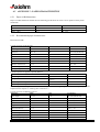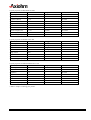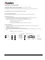
1
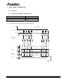
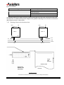
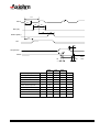
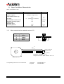
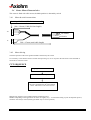
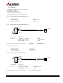
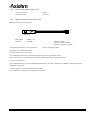
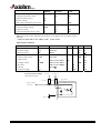
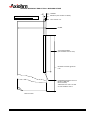
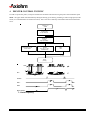
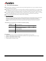
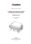
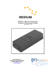
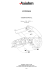
TURNKEY PRINTING SOLUTIONS TA/TB – DA/DB PRINTER USER MANUAL Reference 3107999 Issue Z October - 2004 AXIOHM 1, rue d'Arcueil, BP 820 92542 MONTROUGE CEDEX FRANCE Tel : (33) 1 58 07 17 17, Fax : (33) 1 58 07 17 18 EVOLUTIONS Date 10/2004 Issue Z Modifications Creation TA/TB- DA/DB Printer User Manual Page 1 /32 Reference: FDE – 3107999 Issue Z INTRODUCTION The TA/TB series are highly reliable printer mechanisms especially designed to print and cut very thick thermal paper. (DA/DB: version without cutter) Those mechanisms come with standard features, such as top of form management, end of paper detection, possible reverse feeding. The motor torque allows to handle big paper rolls or folded media to suit as many applications as possible. The specific paper guiding added to a heavy duty guillotine blade give to this mechanisms the ability to cut the thickest thermal media available on the market. The most common Axiohm PCBs available to drive those mechanisms are the ‘Optiboard’ series. The following manual is designed to help the mechanical and electronic integration – Axiohm technical support can be contacted if necessary. TA/TB- DA/DB Printer User Manual Page 2 /32 Reference: FDE – 3107999 Issue Z CONTENTS 1 TECHNICAL SPECIFICATIONS................................................. 5 2 MECHANICAL FEATURES ........................................................ 6 3 2.1 External Dimensions.................................................................................. 6 2.2 Housing features for ticket access .............................................................. 8 2.3 Paper entry and exit .................................................................................. 8 ELECTRIC INTERFACE ............................................................. 9 3.1 Overview: .................................................................................................. 9 3.2 General Print Head Characteristics........................................................... 9 3.2.1 Fonction of each 64 bit IC (integrated circuit) ............................... 9 3.2.2 Routing of data to the thermistor dots ......................................... 10 3.2.3 Timing Chart ............................................................................ 11 3.2.4 Print head connection ................................................................ 12 3.3 Paper Feed Motor Characteristics ........................................................... 13 3.3.1 Motor connections for standard versions (J15)............................. 13 3.3.2 Induction sequence and timing for standard motor ....................... 14 3.3.3 Acceleration curve for standard motor ........................................ 14 3.4 Cutter Motor Characteristics .................................................................. 15 3.4.1 Motor & switch connections ...................................................... 15 3.4.2 Motor driving ........................................................................... 15 3.5 Stepper Motors Electric Control (paper feed) .......................................... 16 3.5.1 Used Driver.............................................................................. 16 3.5.2 Driving cycle............................................................................ 16 3.6 Sensors .................................................................................................... 17 3.6.1 End of paper switch characteristics............................................. 17 3.6.2 End of paper switch connection (J7) ........................................... 17 3.6.3 Cover switch connection (J6) .................................................... 17 3.6.4 Cutter switch characteristics (J5) ................................................ 18 3.6.5 Optical sensors characteristics (J10) ........................................... 18 4 PRINTER CONTROL TECHNIC ............................................... 21 5 RECOMMENDATIONS ............................................................. 22 5.1 Mechanical Recommendations................................................................. 22 5.2 Recommendations for Electronic ............................................................. 22 5.3 Recommendations for paper.................................................................... 23 5.5 Cleaning your printer .............................................................................. 23 5.6 General Recommendations ...................................................................... 24 TA/TB- DA/DB Printer User Manual Page 3 /32 Reference: FDE – 3107999 Issue Z 6 APPENDICES............................................................................. 25 6.1 APPENDIX 1 : PRINT-HEAD THERMISTOR ...................................... 25 6.2 APPENDIX 2 : PAPER CHARACTERISTICS ....................................... 26 6.2.1 Paper width dimensions............................................................. 26 6.2.2 Recommended paper characteristics ........................................... 26 6.3 APPENDIX 3 : HEATING TIME CALCULATION................................ 28 6.3.1 Real heating times..................................................................... 28 6.3.2 History control.......................................................................... 29 APPENDIX 4 : HEATING TIME ..................................................................... 31 TA/TB- DA/DB Printer User Manual Page 4 /32 Reference: FDE – 3107999 Issue Z 1 TECHNICAL SPECIFICATIONS The following table gathers the main characteristics of the printing unit. ITEM VALUE UNIT Printing method -- Paper loading Number of resistor dots Resolution Printing width Max Printing speed Static thermal dot line printing Autoload/Automatic 640 8 horizontal & vertical 72/80 130 -dots Dots/mm mm mm/s Paper width (TAxx / TBxx) 80 / 82.5 mm Head T° detection Paper feed pitch By Thermistor 0.125 -mm Paper empty detection TOF Operating voltage range Vcc (logic) By switch Option: optical-sensor 4.5 - 5.5 (5V±10%) 21.6 - 26.4 (24V±10%) 26 --V DC mA per resistor dot "on" at 24V 50 mA 0.15 500 mJ mA per activated phase at 24V 16.7 A 152.6 87.1 112.2 838 -40 to +80 mm mm mm g °C Relative humidity*2 no condensing Operating range*2 20 to 90 (up to 35°C) 20 to 80°C (up to 50°C) -10 to +50 % Electrical lifetime *3 pulses on OE signal Mechanical lifetime *3 2 x 10⁸ 150 Cutter lifetime Up to 500K cuts Vch (dot) Current Consumption : Vch Max Current Consumption: Vcc (all dots "on") Nominal dot energy (High sensitivity paper) Current Consumption: Stepping motor Peak print head current (all dots ”on ” at nominal value) Over all dimensions: Width Depth Height Weight Storage range*2 V DC °C km *1 In standard conditions: 24 Volts, 25°C, for a print head with a resistance of 950 Ω, at 1042 PPS *2 Contact Axiohm for recommendations if extended conditions are required *3 Per AXIOHM conditions TA/TB- DA/DB Printer User Manual Page 5 /32 Reference: FDE – 3107999 Issue Z 2 MECHANICAL FEATURES 2.1 External Dimensions 290 ± 10mm Paper inlet Only the straight paper path is available on these mechanism versions TA/TB- DA/DB Printer User Manual Page 6 /32 Reference: FDE – 3107999 Issue Z Sheet metal cover Thick paper cutter Specific paper guide for thick paper paper path edge Useful distances for Top of form management middle paper path paper edge Distance from the optical sensor to the line of cut : 79.5 ± 1 mm Distance from the line of dots to the line of cut: 35 ± 1 mm 8 mm 34 mm 34 mm 8 mm 6.3 mm for 80 mm mechanisms 7.5 mm for 82.5 mm mechanisms The optical sensors can be placed on both sides of the paper path. They can face the back side of the paper. TA/TB- DA/DB Printer User Manual Page 7 /32 Reference: FDE – 3107999 Issue Z 2.2 Housing features for ticket access See section “Recommendations”. 2.3 Paper entry and exit The paper must be guided to reach the mechanism paper inlet. The guide must be designed in such a way that it does not stop the paper or mark it, or create high friction. If the application requires a paper guide at the mechanism paper exit, make sure the paper is not bent too much otherwise a jam will occur. The design of the mechanism guide at the paper exit is optimized to cut thick paper. If an exit guide is added, leave enough space so that it does not obstruct the mechanism guide and prevent the internal paper guide from working properly. PAPER ENTRY EXIT ANGLE Exit Guiding : ± 10° The paper should be guided as shown on the drawing here after. Smooth curves are preferred to drive the paper (in or out). In case of doubt when designing the guides, contact your Axiohm representative. 22 mm Entry Guiding : ± 20° TA/TB- DA/DB Printer User Manual Page 8 /32 Reference: FDE – 3107999 Issue Z 3 ELECTRIC INTERFACE 3.1 Overview: 3.2 General Print Head Characteristics Number of dots Number of driver ships Dot resistance Maximum current per dot line (at 24V) 3.2.1 640 10 (64 dots per ships) 950 ± 3 % Ω 16.2A Fonction of each 64 bit IC (integrated circuit) Vch 1 2 3 4 ...... (OUTPUTS).... 62 63 64 Line of resistor dots GND Output Enable (OE) OE Strobe 64 bits buffer register Serial Input (SI) 64 bits shift register CLOCK SERIAL OUTPUT (SO) TA/TB- DA/DB Printer User Manual Page 9 /32 Reference: FDE – 3107999 Issue Z Driver IC schematic These circuits are supplied by 4,5V to 5.5V logic voltage 64 open collector transistors Each circuit features 64-bit shift register 64-bit memory register Each circuit controls 64 resistor dots on the print head The heating element power supply VCH is not connected to the Driver ICs but to the resistive line of dots itself. The driver ICs are connected via a pattern of high current gold interconnecting traces to the line of resistor dots. (Heat element structure: 2 heaters/dot) 3.2.2 Routing of data to the thermistor dots R64 Resistors R1 R64 CHIP n SI R1 Resistors CHIP n+1 SO SI SO OUT IN CLK Strobe OE n OE n+1 Paper path direction Data input Sensitive side Print head bottom view (chip side) Thermal Dots print order The first bit of data entered will be the first bit of data printed (FIFO). TA/TB- DA/DB Printer User Manual Page 10 /32 Reference: FDE – 3107999 Issue Z 3.2.3 Timing Chart 1 / t1 Clock t2t t3 t4 DIN (SI) t5 t6 Strobe (latch) t7 SO t8 OE (strobe) t8 DOUT t9 Min Typ Clock frequency t10 Max 6.25 Mhz Clock pulse width t2 70 ns Clock SI set up time Clock SI hold time Latch pulse width Clock latch setup time SO Delay time OE-DO delay time t3 t4 t5 t6 t7 t8 40 40 100 100 ns ns ns ns ns DO fall time t9 DO rise time t10 TA/TB- DA/DB Printer User Manual Page 11 /32 90 % 50% 10% 120 10.5 µs 3.5 10 µs 2.0 6.0 µs Reference: FDE – 3107999 Issue Z 3.2.4 Print head connection The following table provides the standard printing speed version. Pin n° 1 Signal Vch (heating) Pin n° 2 Signal Vch 3 5 7 9 11 13 15 17 19 21 23 25 27 29 Vch Data - in OE 5 Thermistor 1 GND GND GND GND GND OE 2 Vcc (logic) Strobe Vch Vch 4 6 8 10 12 14 16 18 20 22 24 26 28 30 Vch NC OE 4 Thermistor 2 GND GND GND GND OE 3 OE 1 Clock Data - Out Vch Vch Contact side 30 1 30 pin compatible connectors (to be fitted on the controller board) connector ZIF 30 Compatible connector suppliers and references: Molex 5597 3951 3304 straight connector Molex 5597 3951 3303 bent connector Stocko MZF 9390 60 3030 straight connector Stocko MZF 8900 60 3030 bent connector TA/TB- DA/DB Printer User Manual Page 12 /32 Reference: FDE – 3107999 Issue Z 3.3 Paper Feed Motor Characteristics Motor for standard versions: Recommended control voltage 24 VDC Coil resistance 8 Ω 2 (Bipolar Chopper 2-2P) 0.125 7.5 (48 steps per revolution) 500 400 mm ° mA/phase step/s 1040 600 step/s gr Number of phases Paper feed for 1 motor step Step angle Recommended control current Maximum starting frequency (with no load) Maximum speed Maximum pull force 3.3.1 Motor connections for standard versions (J15) PIN n° 1 2 3 4 Wire color yellow orange brown black 3 1 280 4 2 +20 -10 master spline on opposite side 1 (yellow) Connector : JST PHR - 4 - R Gold plated contacts SPH - 002GA - PO . 5S gear side view Corresponding contact to be set on the board: TA/TB- DA/DB Printer User Manual gold plated tin plated Page 13 /32 JST B4B-PH-K-G JST B4B-PH-K Reference: FDE – 3107999 Issue Z 3.3.2 Induction sequence and timing for standard motor Step 1 2 3 4 current into winding A BLACK + + Colour ORANGE BROWN + + + + - Currents removed t1 t2 current into winding B Currents restored Motor Steps 3.3.3 YELLOW + + Acceleration curve for standard motor The following table is an example of an acceleration curve that can be used to increase from the maximum starting frequency of motor to 130 mm/s. The curve may need to be modified, depending on the paper roll size and the bucket resistance. This curve has been designed for a paper roll of 90 mm diameter, not mounted to an axle. step number printing speed (mm/s) motor speed (step/second) step motor time (µs) 1 31.25 250 4000 2 52 416 2400 3 62.5 500 2000 4 69.3 555 1800 5 71 568 1760 6 72.6 581 1720 7 89.25 714 1400 step number printing speed (mm/s) motor speed (step/second) step motor time (µs) 9 97.6 781 1280 10 104.1 833 1200 11 111.6 893 1120 12 115.7 926 1080 13 120.1 961 1040 14 125 1000 1000 15 130 1042 960 8 91.9 735 1360 It is also recommended to use this curve if lower speed is necessary or to re accelerate from medium speed. This happens particularly when the dot line heating is divided into several dot groups (for consumption reasons or to avoid going over 60% of dots "on"). TA/TB- DA/DB Printer User Manual Page 14 /32 Reference: FDE – 3107999 Issue Z 3.4 Cutter Motor Characteristics This cutter is fitted with a DC motor, the blade position is detected by switch. 3.4.1 Motor & switch connections Locating side shown (3 & 4 not connected) 100 ± 10 mm (Cable division length) J17 4 3 2 1 1 2 1 3 J5 1 2 3 3.4.2 M + - DC Motor NC MO Switch 280 ± 15 mm (total cable length) Motor driving The home position of the cutter guillotine blade is detected by the switch. It is necessary to test that the switch is closed when powering on, if it is not power the DC motor so that the blade is moved till it closes the switch. CUT SEQUENCE Apply power to the DC motor Check the switch opens When the switch is closed again – reverse the power applied to the DC motor during 25 ms. This balances the motor inertia. Note 1: Only the full cut is available with this mechanism series. Notes 2: Depending on the application the 25ms can slightly vary – To tweak this timing in your development process, check the switch stays closed (meaning the blade stays in correct position). TA/TB- DA/DB Printer User Manual Page 15 /32 Reference: FDE – 3107999 Issue Z 3.5 Stepper Motors Electric Control (paper feed) 3.5.1 Used Driver Even though different motor drivers can be used to apply the cycle described next, Axiohm recommends the use of L6258EX from ST. 3.5.2 Driving cycle There are 4 different conditions for the motor windings: The sequence is: AB AB AB AB AB Where AB stands for : A = positive B = negative This electrical sequence corresponds to a sequence of 4 consecutive mechanical positions. The sequence is repeated 12 times for each revolution (24 for cutter motor). If the phase currents are switched to zero, the position in the sequence must be memorized. When the winding currents are re-applied, the polarities corresponding to the last known position should be used. This ensures that the motor will re-start correctly. Once the initial winding currents have been applied, they must be maintained for a time t1 (t1 > 2 ms). Once this time has passed, the motor can be operated if the winding currents are changed in the usual manner. To take-up the backlash in the gears, please operate the motor for 16 steps before printing. TA/TB- DA/DB Printer User Manual Page 16 /32 Reference: FDE – 3107999 Issue Z 3.6 Sensors - On DA/DB / TA/TB sensors are used as follows : - End of Paper: switch (J7). - Cover Sensor: switch (J6). - Cutter Blade position: switch (J5). - TOF opto sensor (only on certain version- J10) 3.6.1 End of paper switch characteristics 30 mΩ, 100 mA/250 V, -40° C +85° C. - contact resistance : - maximum rating : - operating temperature : 3.6.2 End of paper switch connection (J7) Black 1 (black) 2 3 Red Leads length Connector : 250 ±5 mm : JST PHR - 3 - Y (yellow) golden plated contacts SPH - 002GA - P0 . 5S Corresponding contact to be set on the board: 1 : Black 2 : Not Connected 3 : Red gold plated tin plated JST B3B-PH-K-G JST B3B-PH-K Cover switch characteristics <150 mΩ, 10 mA/5 VDC, -40° C +85° C. - contact resistance : - maximum rating : - operating temperature : 3.6.3 Cover switch connection (J6) Black 1 (black) 2 3 Red Leads length Connector : 260 ±5 mm : JST PHR - 3 - BL (blue) golden plated contacts SPH - 002GA - P0 . 5S Corresponding contact to be set on the board: TA/TB- DA/DB Printer User Manual 1 : Black 2 : Not Connected 3 : Red same as end of paper switch Page 17 /32 Reference: FDE – 3107999 Issue Z 3.6.4 Cutter switch characteristics (J5) 10 mΩ, 5 A/250 V, - contact resistance : - maximum rating : 3.6.5 Optical sensors characteristics (J10) Reflective sensor is described below. 1 2 3 Optical cell Leads length Connector : 360mm ± 10 : JST PHR - 3 Corresponding contact to be set on the board: 1 : Black : Ground 2 : Purple : Diode command 3 : Brown : Transistor reception same as end of paper switch The optical cell is: Kodenshi SG105F (see main characteristic on next page) To use transmitive detection, two identical optical sensors can be placed face to face. In this case the sensor cell will be the same as described but the connection has to be defined. For Top of form detector : It is recommended to have a 0.7 min. Macbeth optical density (20% max. reflectance) to 900NM* infrared light for the black mark on the paper. * Use the D filter to measure with the Macbeth PCM II See specifications in chapter 2.5 on Optical sensor position. TA/TB- DA/DB Printer User Manual Page 18 /32 Reference: FDE – 3107999 Issue Z Absolute Maximum ratings SYMBOL RATING UNIT LED Continuous Forward Current Pulsed forward current * Reverse voltage Max. Power Dissipation at 25°C max If IFP VR P 50 1 5 75 mA A V mW PHOTO-TRANSISTOR Collector Emitter Voltage Collector Current Collector Dissipation at 25°C max VCEO IC PC 30 20 50 V mA Mw Note: Driving the sensor with pulse current allows to use higher current to improve paper detection. * (Time On, Time Off) T On = 100µs, T On + T Off = 10 ms Input/Output Conditions LED Forward voltage Reverse current TRANSFER CHARAC. Collector dark current Light Current Leakage Current Rise time Fall time Peak wave length SYMBOL CONDITIONS VF IR ICE0 IL ICE0D tr tf Min. Max. UNIT IF=10 mA VR=5v 1.3 10 V VCE=10V VCE= 5V, IF=10mA VCE= 5V, IF=10mA VCE= 2V, IC=100µA 200 nA µA nA µs µs nm 90 RL= 1kΩ λp External Circuit Example (with pulsed current) Vcc (5V) 4.7 kΩ TYP. 200 30 25 940 µA 5V pulse Opto-sensor 68 Ω Analog / Digital Convertoer green 1 2 orange 3 black GND TA/TB- DA/DB Printer User Manual Page 19 /32 Reference: FDE – 3107999 Issue Z MACHINE READABLE END-OF-ROLL WARNING STRIPE 12MMMIN 5MM MAX. (MAY EXTEND TO EDGE) VIEW OF NON-THERMAL LAST PARTIAL CUT 82,5MM, 30 INCHES MINIMUM (MAY EXTEND TO ROLL END) DESIRED FOOTAGE @ PAPER LOW 0.7 MINIMUM MACBETH OPTICAL DENSITY (20% MAX. REFLECTANCE) *MEASURE WITH THE D FILTER ON THE MACBETH PCM II END OF PAPER TA/TB- DA/DB Printer User Manual Page 20 /32 Reference: FDE – 3107999 Issue Z 4 PRINTER CONTROL TECHNIC In order to operate the printer, we depict hereafter the mode that will allow driving the printer with maximum speed. Mode: The paper feeds itself automatically during the heating cycle thereby permitting to achieve high speed (in this mode, it is recommended to use historical control). This is the most commonly used method with those mechanisms series. Printing of n dot line Transmission of data in series (Din) in step with CLK Transfer to memory stage (STROBE) Heating controlled through OE 1,OE 2,...OEn simultaneously Transmission of next series of data Motor feed 1 to n End of printing CLK T Din N Strobe OE 1 OEn Motor Steps T : Clock frequency TA/TB- DA/DB Printer User Manual Page 21 /32 Reference: FDE – 3107999 Issue Z 5 RECOMMENDATIONS 5.1 Mechanical Recommendations 1 - Make sure the mechanism is fixed to a plane mounting surface as shown on next drawing. This is necessary whether the mechanism is mounted to its front or underneath surface. Front plane mounting surface to set the mechanism. (tolerance 0.1 mm) Underneath plane mounting surface to set the mechanism. (tolerance 0.1 mm) The fixing surfaces should be set to a plane surface 2 - Never apply mechanical stress to the mechanism (other than the necessary stress to fix the mechanism on a plane surface as described above). This could result in print-head misalignment and thus degrading the print quality. A good way to achieve this is to leave some freedom to some of the fixing points. 3 - The thermal print head must have 1 degree of freedom of movement. Never prevent the print head from pivoting on its axis. 5.2 Recommendations for Electronic IMPORTANT: If the line of dots (Vch, 24 V) is supplied before the control logic (Vcc, 5V), resistor dots may be destroyed. Because the control logic has a random state, resistors might be heated for a longer period than the specified maximum burning out the heated resistor. To avoid this, we recommend applying the heating voltage (Vch, 24V) after the logic supply voltage (Vcc, 5V). When first applying Vch, make sure the OEs level is 0 in order to avoid the dot heating before sending data. The same precaution should be taken when shutting down. The supply voltage Vch must be switched off before the logic supply voltage Vcc. Care should be taken to allow enough time for residual capacitive charge to dissipate. To reduce the peak current drawn from the power supply, it is recommended to use a storage capacitor of 1000 to 1200 µF/35V. TA/TB- DA/DB Printer User Manual Page 22 /32 Reference: FDE – 3107999 Issue Z 5.3 Recommendations for paper Use a paper classified with an AXIOHM Part number (or approved by Axiohm). Make sure the paper stock spool is free to turn. With the acceleration curve of the paper feed motor given in this manual, the paper feed motor can pull with a maximum force (see chart in chapters 3.2 and 3.3) without affecting the printing quality. For common rolls of paper (and on common supports) this force corresponds to a roll diameter of 115mm sliding in its bucket. Above this value (or if the bucket and paper path friction are high), use an axle to set the roll (maximum diameter 200mm). If bigger rolls are required contact your Axiohm representative: a specific mechanical design and/or a specific acceleration curve may be required, and the printing speed may be affected. The roll of paper must be exactly “on line” (perpendicular to the printer mechanism) and parallel to the paper inlet in order to avoid paper tracking. Paper inlet path must be designed to avoid obstacles on paper edges. The printer should not operate without paper or this will damage the surface of the rubber roller. Note that the sensitivity of the paper has a direct impact on the mechanism’s performance (in terms of speed). Make sure the chosen paper corresponds to your needs. 5.5 Cleaning your printer The TA/TB DA/DB printer mechanism is a high reliability unit, which requires very little maintenance, but can benefit from cleaning as follows. Depending on the environment in which the printer is used, the printer can accumulate dust. Therefore it is necessary to clean it periodically in order to maintain good print quality. The frequency of cleaning also depends on the environment and the use of the printer; but, the print head should be cleaned at least once a year, or up to one month in heavy duty applications. The print head should always be cleaned immediately if the print becomes visibly fainter due to contamination of the print head. Cleaning instructions: Switch off printer. Never clean the head immediately after printing for the head may be hot. Open the cover of the printer and remove the roll of paper roll. Clean the heating dots of the head with a cotton stick containing a solvent alcohol (ethanol, methanol, or IPA), but do not touch the print head with your fingers. Allow the solvent to dry. Reload the paper and close the cover. N.B.: AXIOHM can provide cleaning kits P/N: CK80000A TA/TB- DA/DB Printer User Manual Page 23 /32 Reference: FDE – 3107999 Issue Z 5.6 General Recommendations Ensure that there is adequate air circulation around the print head support/heat sink, for poor ventilation of the print head can degrade the print quality. Depending on the uses (high current set in the motor phases, integration of the mechanism in a very tight housing, high temperature), it may be necessary to set a duty cycle time to avoid overheating of the paper feed motor. In this case, tests must be made by the mechanism integrator. The temperature should not exceed 80°C on the motor frame. For Clamshell applications, the mechanism cannot be opened when the rotating blade is stopped in its cutting position. The rotating blade must be in such a position that the paper path is opened (cutter switch closed). Never open the mechanism while printing or when the cutter is operating. Duty cycle restrictions : There are restrictions on the duty cycle because of the heat generated by the receipt thermal print head, when printing solid blocks (regardless of the length of the block in relation to the print line). The restrictions are ambient temperature, the percentage of time (measured over one minute) of continuous solid printing, and the amount of coverage. Another cause for duty cycle restriction is paper feed motor temperature increase due to continuous printing. Allowable Duty Cycle (measured over one minute of continuous printing) Amount of Solid Coverage Ambient Temperature 25°C 35° C 50° C 20% 100% during the first 3 minutes of continuous printing. 50% after 3 minutes. 50% 20% 40% 50% 25% 10% 100% 20% 10% 4% For reference: A typical receipt with text (contains some blank spaces) is approximately 12% dot coverage. A full line of text characters (every cell on the line has a character in it) is approximately 25% dot coverage. Graphics are approximately 40% dot coverage. Barcodes are approximately 50% dot coverage. A solid black line is 100% dot coverage. TA/TB- DA/DB Printer User Manual Page 24 /32 Reference: FDE – 3107999 Issue Z 6 APPENDICES 6.1 APPENDIX 1 : PRINT-HEAD THERMISTOR GENERAL CHARACTERISTICS Maximum operating temperatures -50° C to + 400° C Rated resistance at 25° C Rn = 30 kΩ Tolerance for Rn 5% Thermal dissipation constant > 0.3 mW/°C Thermistor time constant (in air) t = 1.5 sec This thermistor has a rated value of 30 kΩ. Its resistance variation can be expressed as follows: R = Rn exp B ( 1 T 1 ) Tn where T is in Kelvin degrees (°K) B = 3950° K ± 3% Rn = reference value at temperature Tn (298° K) Note: that printing should be stopped if the thermistor value goes over 60°C. TA/TB- DA/DB Printer User Manual Page 25 /32 Reference: FDE – 3107999 Issue Z 6.2 APPENDIX 2 : PAPER CHARACTERISTICS 6.2.1 Paper width dimensions Paper roll width dimensions should meet the following specifications to ensure correct operation of the printer mechanism. Product Paper width Tolerance DAxx / TAxx DBxx / TBxx 80 82.5 ± 0.3 +0 -0.4 6.2.2 Recommended paper characteristics Kanzan KL415 SB+ Typical properties of KL415 SB+ Properties Value Units Test method 2 Basis weight 182 ± 12 g/m ISO 536 (JIS P8124) Thickness 183 ± 12 75 min. µm ISO 534 (JIS P8124) % ISO 2470 (JIS P8123) Smoothness 500 min. Sec ISO 5627 (JIS P8119) Image colour black - Initial activation T° 70 ± 5 °C (D) = 0.2 80 ± 5 Tensile strength (MD/CD) >6.8/>3.4 °C (D) = 0.8 Kn/m ISO 1924/1 Tearing strength (MD/CD) >950/>950 mN ISO 1974 Brightness Effective activation T° Typical Properties of Appleton Optima T886-B Topic Value Unit Basis Weight 82.3 ± 4.1 g/m2 Calliper 81.3 ± 7 Microns Static temperature response for O.D. = 0.2 79.4 ± 5 °C °C Static temperature response for O.D. = 1 93 ± 5 (With this paper an average factor of 1.45 should be applied to the heating time given; this affects the printing speed as explained in the chapter 6.3 "Heating time calculations ") Typical properties of Blumberg T49-32 Properties Value Units Test method 2 Basis weight 88 ± 3.5 g/m ISO 536 (JIS P8124) Calliper 77 ± 3 70 min. µm ISO 534 (JIS P8124) % ISO 2470 (JIS P8123) Smoothness >350 Sec ISO 5627 (JIS P8119) Image colour black - Initial activation T° 70 ± 5 °C O.D.*) = 0.1 Effective activation T° °C O.D.*) = 1.3 Tensile strength (CD) 115 ± 5 > 2 min. KN/m ISO 1924 (JIS P8113) Tear strength (CD) > 300 mN ISO 1924 (JIS P8116) Head cleaning frequency 10 maxi. km Brightness TA/TB- DA/DB Printer User Manual Page 26 /32 Reference: FDE – 3107999 Issue Z Typical properties of Mitsubishi TP 8065 Properties Value Units Test method 2 Basis weight 82 ± 5 g/m ISO 536 Calliper 87 ± 5 µm ISO 534 Brightness (R457) 92 ± 4 % ISO 2469 Smoothness (Bekk) Sec ISO 5627 Image colour 750 ± 250 Black - - Initial activation T° 85 °C - Effective activation T° 100 °C - Tensile strength (CD) 80 ± 10 N/15mm ISO 1924/1 Tear strength (CD) 40 ± 10 * N/15mm ISO 1924/1 - - Head cleaning frequency Typical properties of Kanzaki Lotto 480 Properties Value Units Test method Basis weight 83.2 g / m2 avg Calliper 83.3 µm avg TAPPI T-410 TAPPI T-411 Brightness 89 % avg TAPPI T-525 Smoothness 1500 Sec avg TAPPI T-479 Image colour Black - - Initial activation T° 80 ± 5 °C - Effective activation T° 90 ± 5 * °C - - - Head cleaning frequency Typical properties of Sihl PrintTherm 80 P 7 CS Properties Value Units Test method 2 Basis weight 82 ± 8 g/m ISO 536 Calliper µm ISO 534 Brightness 83 ± 8 > 75 % ISO 2470 Smoothness > 500 Sec Image colour Black - ISO 5627 - Initial activation T° 78 °C - Effective activation T° 105 °C Head cleaning frequency * - - * Refer to chapter "Cleaning your printer". TA/TB- DA/DB Printer User Manual Page 27 /32 Reference: FDE – 3107999 Issue Z 6.3 APPENDIX 3 : HEATING TIME CALCULATION 6.3.1 Real heating times Heating time versus voltage and temperature: Tch (saturation heating time) Température statique Voltage Temperature Paper Coeff "a" Coeff "b" Voltage Speed Paper Coeff "c" Coeff "d" Coeff "g" Coeff "h" Coeff "i" Coeff "j" Temperature Speed Paper Coeff "e" Coeff "f" 0,440 ms 100 °C At Nominal Voltage & Nominal Temperature Heating Time vs Speed 24 Volts 25 °C KL415SB+ 0,3826 1,0150 t 2 = t1 × (a × Log(tm) + b) tm = Time for motor step (ms) At Nominal Speed & Nominal Voltage Heating Time vs Temperature 24 Volts 130mm/s KL415SB+ -0,0087 1,2175 -0,00000161 0,000173 -0,013690 1,259449 t 3 = t 2 × ( cT + d ) For polynomial modelisation * t3 = t2 × ( g × T3 + hT2 × iT + J) At nominal Temperature & Speed Heating Time vs Voltage 25 °C 130mm/s KL415SB+ 1,1192 -2,6037 V '= eV + *: Recommended by Axiohm (more accurate) TA/TB- DA/DB Printer User Manual Page 28 /32 Reference: FDE – 3107999 Issue Z f 6.3.2 History control The history coefficient depends on the speed (explained below). It gives the reduction (in %) of the TCH (nominal heating time), which has to be applied on a dot previously heated (on N-1 or N-2 dot line). Paper feed motor control parameters: Min Speed = 23 mm/sec Max Speed = 130 mm/sec Ramp Size = 32 Speed = MIN_SPEED + (MAX_SPEED - MIN_SPEED) x Index / (RAMP_SIZE-1) History control : Tb = (COEFA x ln(6.25) + COEFB) Tb = 1,716 TbTmp = (COEFA x ln(StepTime/1000) + COEFB) HistTmp = 110 x (Tb-TbTmp) / Tb if (HistTmp < 0) HistCoef = 0 else HistCoef = HistTmp TA/TB- DA/DB Printer User Manual Page 29 /32 Reference: FDE – 3107999 Issue Z Index Step Time (µs) Speed (mm/sec) History Coef (%) History control 0 1 2 3 4 5 6 5435 4726 4180 3748 3396 3105 2860 23 26 30 33 37 40 44 3 6 8 11 13 15 17 Raster (N) 1 Raster (N-1) 0 Raster (N-2) 0 1 0 1 1 1 0 1 1 1 0 1 1 1 7 8 9 10 11 12 13 14 15 16 17 18 19 20 21 22 23 24 25 26 27 28 29 30 31 2650 2470 2312 2173 2050 1940 1842 1753 1672 1598 1530 1468 1411 1358 1309 1263 1221 1181 1144 1109 1076 1045 1015 988 962 47 51 54 58 61 64 68 71 75 78 82 85 89 92 95 99 102 106 109 113 116 120 123 127 130 19 20 22 23 24 26 27 28 29 30 31 32 33 34 34 35 36 37 37 38 39 39 40 41 41 TA/TB- DA/DB Printer User Manual HistoryEn Actual heating time = TCH x (1 - HistoryCoef x HistoryEn) Page 30 /32 Reference: FDE – 3107999 Issue Z APPENDIX 4 : HEATING TIME The heating timetable is presented on the following page (given for paper: KL415SB+) The print-head resistance to obtain this table was 950 Ω. The timetable gives the required heating time, giving the necessary energy to obtain an optical density of 1.2. The heating time must always be shorter than the motor cycle time. How to use the heating timetable? The heating time can be controlled either with or without historical control as described here after. Without historical control: - Take the indicated heating time from the timetable (definition of voltage and temperature and speed) - We do not take into account the history control (⇒ History EN always = 1). - At high speed, printing quality for isolated dots might be affected with this method. Example: at 130mm/s, 25°C and 24 volts TCH = 362 µs (from the table) In this mode only one serialisation of data is necessary for one dot line. With historical control: - In this mode, the actual heating time is different depending on if the dots have been previously heated or not. (History EN = 1 or 0) - This method gives the best printing quality. - With this mode, two serialisation data are necessary for one dot line. - The first one will be all the data, and the second one will be only the dots not heated previously on lines (N-1) and (N-2). Example: at 130 mm/s, 25°C and 24 volts: N-2 N-1 dot to heat HistoryEN = 1 = dot ON Heating time to apply 0.362 ms HistoryEN = 1 = dot OFF 0.362 ms HistoryEN = 0 0.621 ms (base heatingtime) TA/TB- DA/DB Printer User Manual Page 31 /32 Reference: FDE – 3107999 Issue Z Heating time table Paper: KL 415 SB Voltage (V) Temperature (°C) Real Virtual Temps moteur pour un pas Temps moteur pour une sous ligne 20,00 20,00 20,00 20,00 20,00 20,00 20,00 22,00 22,00 22,00 22,00 22,00 22,00 22,00 24,00 24,00 24,00 24,00 24,00 24,00 24,00 26,00 26,00 26,00 26,00 26,00 26,00 26,00 28,00 28,00 28,00 28,00 28,00 28,00 19,78 19,78 19,78 19,78 19,78 19,78 19,78 22,02 22,02 22,02 22,02 22,02 22,02 22,02 24,26 24,26 24,26 24,26 24,26 24,26 24,26 26,49 26,49 26,49 26,49 26,49 26,49 26,49 28,73 28,73 28,73 28,73 28,73 28,73 0 °C 10 °C 20 °C 25 °C 30 °C 40 °C 50 °C 0 °C 10 °C 20 °C 25 °C 30 °C 40 °C 50 °C 5 °C 10 °C 20 °C 25 °C 30 °C 40 °C 50 °C 0 °C 10 °C 20 °C 25 °C 30 °C 40 °C 50 °C 0 °C 10 °C 20 °C 25 °C 30 °C 40 °C Speed (mm/s) < 20 mm/s 6,250 ms 6,250 ms 1,176 ms 1,063 ms 0,973 ms 0,934 ms 0,897 ms 0,827 ms 0,753 ms 0,949 ms 0,858 ms 0,785 ms 0,754 ms 0,724 ms 0,667 ms 0,608 ms 0,742 ms 0,707 ms 0,647 ms 0,621 ms 0,597 ms 0,550 ms 0,501 ms 0,655 ms 0,592 ms 0,542 ms 0,521 ms 0,500 ms 0,461 ms 0,334 ms 0,443 ms 0,401 ms 0,367 ms 0,352 ms 0,338 ms 0,312 ms TA/TB- DA/DB Printer User Manual 50 mm/s 2,500 ms 2,500 ms 0,936 ms 0,846 ms 0,774 ms 0,743 ms 0,714 ms 0,658 ms 0,599 ms 0,755 ms 0,683 ms 0,625 ms 0,600 ms 0,576 ms 0,531 ms 0,483 ms 0,591 ms 0,562 ms 0,515 ms 0,494 ms 0,475 ms 0,438 ms 0,398 ms 0,522 ms 0,471 ms 0,432 ms 0,414 ms 0,398 ms 0,367 ms 0,303 ms 0,402 ms 0,363 ms 0,333 ms 0,319 ms 0,307 ms 0,283 ms 70 mm/s 1,790 ms 1,790 ms 0,848 ms 0,767 ms 0,702 ms 0,674 ms 0,647 ms 0,596 ms 0,543 ms 0,685 ms 0,619 ms 0,566 ms 0,544 ms 0,522 ms 0,481 ms 0,438 ms 0,535 ms 0,510 ms 0,467 ms 0,448 ms 0,430 ms 0,397 ms 0,361 ms 0,473 ms 0,427 ms 0,391 ms 0,375 ms 0,361 ms 0,332 ms 0,290 ms 0,385 ms 0,348 ms 0,318 ms 0,306 ms 0,294 ms 0,271 ms Page 32 /32 R= 80 mm/s 2,500 ms 2,500 ms 0,812 ms 0,734 ms 0,672 ms 0,645 ms 0,620 ms 0,571 ms 0,520 ms 0,655 ms 0,592 ms 0,542 ms 0,521 ms 0,500 ms 0,461 ms 0,420 ms 0,512 ms 0,488 ms 0,447 ms 0,429 ms 0,412 ms 0,380 ms 0,346 ms 0,453 ms 0,409 ms 0,375 ms 0,359 ms 0,345 ms 0,318 ms 0,279 ms 0,371 ms 0,335 ms 0,307 ms 0,294 ms 0,283 ms 0,261 ms 90 mm/s 1,790 ms 1,790 ms 0,782 ms 0,707 ms 0,647 ms 0,621 ms 0,597 ms 0,550 ms 0,501 ms 0,631 ms 0,570 ms 0,522 ms 0,501 ms 0,481 ms 0,444 ms 0,404 ms 0,493 ms 0,470 ms 0,430 ms 0,413 ms 0,397 ms 0,366 ms 0,333 ms 0,436 ms 0,394 ms 0,361 ms 0,346 ms 0,333 ms 0,306 ms 0,269 ms 0,357 ms 0,323 ms 0,296 ms 0,284 ms 0,273 ms 0,251 ms 942 Ohms 100 mm/s 1,560 ms 1,560 ms 0,754 ms 0,682 ms 0,624 ms 0,599 ms 0,575 ms 0,530 ms 0,483 ms 0,609 ms 0,550 ms 0,503 ms 0,483 ms 0,464 ms 0,428 ms 0,390 ms 0,476 ms 0,453 ms 0,415 ms 0,398 ms 0,383 ms 0,353 ms 0,321 ms 0,420 ms 0,380 ms 0,348 ms 0,334 ms 0,321 ms 0,296 ms 0,260 ms 0,346 ms 0,313 ms 0,286 ms 0,275 ms 0,264 ms 0,243 ms 110 mm/s 1,390 ms 1,390 ms <None> 0,660 ms 0,604 ms 0,580 ms 0,557 ms 0,513 ms 0,467 ms 0,589 ms 0,532 ms 0,487 ms 0,468 ms 0,449 ms 0,414 ms 0,377 ms 0,461 ms 0,439 ms 0,402 ms 0,385 ms 0,370 ms 0,341 ms 0,311 ms 0,407 ms 0,368 ms 0,337 ms 0,323 ms 0,310 ms 0,286 ms 0,244 ms 0,325 ms 0,293 ms 0,269 ms 0,258 ms 0,248 ms 0,228 ms Reference: FDE – 3107999 Issue Z 130 mm/s 1,250 ms 1,250 ms <None> <None> <None> 0,544 ms 0,523 ms 0,482 ms 0,438 ms 0,553 ms 0,500 ms 0,457 ms 0,439 ms 0,422 ms 0,389 ms 0,354 ms 0,432 ms 0,412 ms 0,377 ms 0,362 ms 0,347 ms 0,320 ms 0,292 ms 0,382 ms 0,345 ms 0,316 ms 0,303 ms 0,291 ms 0,268 ms 0,334 ms 0,443 ms 0,401 ms 0,367 ms 0,352 ms 0,338 ms 0,312 ms