1
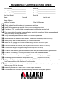
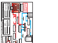
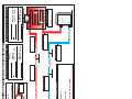
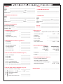
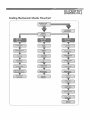
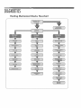
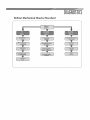
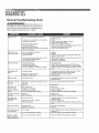
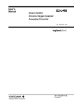
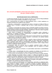
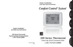
Allied HVAC Distributors Technical Service Reference Guide October 2014 CUSTOMER SERVICE IS OUR PASSION The intent of this booklet is to guide our customers on how to best utilize the resources of our Technical Support resources. Please don’t hesitate to contact us with any questions you might have regarding the services we offer. Table of Contents PAGE Technical Service Calls…..…..………….………….………….………………...1 TSM Jobsite Visits…………....………….……………………………………….2 DOA Policy…………………....………….……………………………………….3 Technical Training…………....………….……………………………………….4 Frequently Asked Questions (F.A.Q’s)……….………………………………….5 Click on any item to be taken to that page. Click on any page heading to be taken back to the table of contents Supporting Documents Appendix Residential Commissioning Sheet………………………………………………...A Heat Pump Jobsite Information Sheet…………………………………………...B Air Conditioning Jobsite Information Sheet…………………………………….C 80% Gas Furnace Jobsite Information Sheet..…………………………………..D 90% Gas Furnace Jobsite Information Sheet……………………………………E Oil Furnace Jobsite Information Sheet……….…..…….………………………..F Suggested Service Van Tool List……………...…………………..….…………..G RUUD Diagnostic Flow Charts..………………………………………………….H Fujitsu Halcyon Troubleshooting Guide…………………………………………I Training Course Cancellation Policy: We encourage people to sign up online for courses and to do so early to insure a seat is reserved in their name. Please note that we reserve the right to cancel a course at least one week in advance when attendance is below our minimum, which changes based on subject matter and length of class. Training Course No Shows: There are significant costs incurred to produce a training course, including printing, travel, lodging, meals, snacks and drinks. Please note that no shows, those who sign up for courses, but don’t show up or cancel within 24 hours of the scheduled start time are billed the full tuition. All handouts will be provided to the TM for delivery to the contractor as time permits. Technical Service Calls One of the primary job functions for a technical service manager (TSM) is to assist our customers in solving problems over the phone. To maximize that effort we attempt to record all incoming technical support calls. The records we keep are then used to identify trends in service or warranty, allowing us to be proactive in reporting back to RUUD’s technical support department. It also helps technicians obtain more accurate support if they call back with follow up information days or weeks later because we keep accurate records on what direction was provided at the time of the original call. So prior to making the call and as a way to increase the likelihood the TSM can help resolve your issue please have the following information at the ready: Technician contact information such as first/last name, company name, company phone and cell phone Model and Serial # (both indoor and outdoor if split system) Date Installed and date failed Description of the problem, including as many specifics as possible Temperatures, pressures and all operational data that may assist the TSM in finding the resolution In fact, to better serve you we recommend having a diagnostic or start up sheet completed prior to making the call. We have sheets for residential and/or commercial A/C and heat pumps, ground source heat pumps, mini split systems and gas furnaces. These sheets are available to download from our available forms page. To insure you have the means to complete these sheets please see Appendix G for the list of tools we suggest be on every service van. These tools are vital to insuring a professional start up, commissioning or troubleshooting effort. Please don’t hesitate to contact us if you have questions on what tools are needed to obtain the data for these sheets. TSM Jobsite Visits Jobsite visits are another valuable service provided by a TSM, with the goal to always resolve issues as efficiently as possible. In order to meet our phone support goals, site visits must be scheduled with as much advance notice as can be provided and we ask that you keep in mind only the TSM or the Director of Technical Service can schedule a site visit. A service technician with all the tools needed to perform the work must be present for any site visit. If the site visit will not involve troubleshooting a system another contractor representative, such as a principle or manager, may be present instead of a service technician. However there must always be a contractor present when a TSM visits a site. NO EXCEPTIONS to this rule are permitted under any circumstances. Site visits can only be made if the TSM has received, in advance, a completed datasheet. The reason behind this requirement is that it is a well proven fact that our TSM can resolve most service and troubleshooting issues from their desks when provided the proper information. The data found on our start up or diagnostic sheets help him get to the core of the problem quickly. By requesting and reviewing this information before considering a site visit he can often spot the problem and provide suggested resolutions without having to leave the office. This information is also required by the factory when we contact them for additional support. An urgent call because a service technician has been to the site 5 times is not as effective as if we are called to assist after the first or second visit. Even if a site visit is not required at that time we can log the information then have it available as reference data at a later time if more action is required. Please help us support you in the most proactive way possible by following the steps below to arrange a site visit: . Provide the TSM with the completed data sheet using fax or email. After entering the data into our call log, reviewing and discussing it with the technician, the TSM may provide suggestions on how to resolve the issue. If the suggested resolutions do not resolve the problem a site visit can then be scheduled. The TSM will schedule the visit at a time most convenient with the system owner and the contractor, with the only limiting factor being the need to insure our minimum phone coverage is met. The TSM will meet the contractor at the jobsite at the designated date and time. The TSM provides supervisory assistance onsite and also records all the data. The technician must have the tools required to complete all anticipated troubleshooting tasks. These tasks may include, but are not limited to, the ability to recover the system charge into a clean empty cylinder, weighing the charge that was removed, evacuating the system to 500 microns and weighing in the correct, calculated charge. For details on the tools we recommend every service van have (or have access to), please see appendix G. After the site visit the TSM will forward, via email or fax, a report to the contractor detailing the suspected cause, resolution and follow up recommendations. All jobsite notes and reports are then entered into our call log. DOA Policy The intent of the Allied HVAC Distributors DOA (Dead On Arrival) policy is to insure consumers and contractors are not forced to accept one of the few units that may come from the factory with a problem that can either not be repaired, or due to concerns for long term reliability, a repair is not an option. This policy is limited to contractors who participate in our marketing programs and who also attend the product training courses. Please see your TM to discuss eligibility. The acronym DOA means dead on arrival so the failure must occur within 30 days of the unit start up to qualify for this program. Failures that occur beyond the first 30 days would be covered by either the factory CCE program or the unit’s standard warranty. Please contact your territory manager or your local TSM to verify coverage. The program guidelines are as follows: Authorization for any unit being returned under this policy must be obtained in advance from a regional vice president, branch/operations manager or technical service manager. The policy only applies to residential condensing units, furnaces and residential packaged units. To qualify the failure must be a non-repairable refrigeration leak, a shorted, open or non-repairable compressor or a defective, non-repairable heat exchanger. To begin the process call our TSM on call to report a unit being DOA. Provide model/serial of the unit along with the reason for failure. o The TSM will log the information and then provide you with a SR# for future reference. The words “DOA SR#” should then be written on the unit being returned to insure proper tracking. o The reason for failure must be specific. “Compressor will not start” or “The unit has a leak” will not be considered specific enough to qualify. Units received without an SR# for tracking cannot be accepted by our warehouse staff or truck drivers. A completed residential start up/data sheet must be provided on the replacement unit. This insures the new unit is operating within acceptable parameters. o Note: Credit for either the unit or the unit and labor (if applicable) are not issued until the completed startup/data sheet has been received by the TSM responsible for the branch where the unit was purchased. This information is then scanned and attached to the service request (SR) in our call log for future reference. Technical Training One of the universal truths about the HVAC industry is that it is constantly evolving and improving. So to keep pace with the introduction of new products and technologies it is absolutely essential for contractors and technicians to evolve and improve as well. Allied takes pride in offering our customers the widest range of technical training opportunities in the industry. Our jobs and lives are typically very busy so making time for training can be a challenge. A contractor will sometimes say “What if I train that technician and he leaves the company?” We’ll always counter by suggesting they ask a different question: “What if I don’t train that technician and he stays?”. Listed below is a list of our current training options: Traditional Classroom Training F2F or Face to Face training has existed since the dawn of time and continues to be the method of choice for a large contingent of contractors and technicians. Last year we developed and introduced a five part series called “C.A.T.” or Callback Avoidance Training. It was very successful and continues as a popular offering for both seasoned and new technicians. We offer a wide range of scheduled training courses in both spring and fall. However please keep in mind that posted courses are added and changed on a very regular basis so we encourage you to visit our webpage often. Anytime Learning Network We understand how difficult it can be to juggle work, home, training and still find a way to enjoy some leisure time. Our ALN offers almost 40 full length training courses that take anywhere from 15 to 25 hours to complete. These courses are used by colleges and universities across the country in a wide range of content such as HVACR Fundamental, Electrical Theory (both AC & DC), Oil Heat, Gas Heat, Heat Pumps, Indoor Air Quality, Troubleshooting, etc.. The courses are rated as beginning, intermediate and advanced. Self-Paced Training Modules Through our partnership with Hardi we offer a full range of printed training materials for those learners who prefer self paced home study courses over F2F or online. Many of these courses are designed non-technical personnel such as office, accounting or warehouse staff whose productivity and efficiency can be improved with a better understanding of the HVAC industry. The courses come in a wide range of topics that include comfort heating, comfort cooling, controls, materials handling, etc. Personalized Training Sessions Whether in response to new hires, when considering a new product line or to simply get up to speed on how to wire a particular system, Allied is there to help. Our TSM can come to your place of business at a time most convenient to your schedule to present whatever material you request. Webinars – Live and Pre-Recorded Webinars are fast becoming a training tool of choice for many organizations. They can be arranged quickly, require no special travel and very little cost. Yet live webinars, typically less than 1 hour in length, allow learners to interact with the presenter in a way that video cannot, while pre-recorded webinars give potential learners the chance to review material they may not otherwise have access to. If you have a need or idea for a webinar, please don’t hesitate to ask as we can arrange the webinar of your choice as soon as time permits. Frequently Asked Questions (F.A.Q’s) The following are a list of common questions often posed to the technical service managers. We hope you find them useful and would encourage you contact your local TSM with any additional questions you might have. We will add to this list from time to time so please be sure to visit our View Available Forms page often to obtain the most recent version of this document. I would like to call the factory directly for technical support. Why will Allied not provide a number to call? As the local RUUD distributor it’s both our responsibility and our desire to support the products we sell. Even if a contractor were to reach out to the factory they will always be redirected back to the local distributor. I have a consumer who is demanding to speak with the factory. Will Allied provide them a contact number? For the same reasons as mentioned above we do not provide the factory technical support number to consumers. Consumers who try contacting the factory directly will always be redirected back to us as the local distributor. We sell only to licensed contractors who then sell those products to consumers. If a consumer has an issue they should first speak to the installing contractor. However we will always do our best to help resolve issues between a consumer and a contractor and we always try to answer consumer questions. I have a design or quality issue that I feel should be brought to the factory’s attention. How can I get this accomplished? Provide your TSM with as much detail as you can, including pictures whenever possible. He will create a report which is then submitted to the factory. The RUUD factory has assured us all such reports will be reviewed and answered. We will then forward that answer to you. This insures your voice is heard and we strongly encourage our contractors to take advantage of this process. How do I determine if the control board or ECM motor is the problem? Verify you have high voltage to the motor and then connect a Tech Mate to the motor. Contact your TSM to obtain this valuable tool. How do I check a X13 motor to verify if it’s not working properly? Verify you have high voltage constant to the motor and then check to see if you have 24v on one of the terminals 1-5. I have a split system application with 128 feet of refrigerant piping. What size line set do I need and what would the refrigerant charge be? You can use the installation instructions along with the long line set application guidelines and our refrigerant line sizing spreadsheet. They can be downloaded from our forms webpage. I have a gas furnace with a variable speed blower. The cfm light on the board tells me it’s delivering 1200 cfm. How can I be sure it is in fact moving 1200 cfm? You can apply the sensible heat formula to quickly and easily determine actual CFM while on the jobsite: CFM=BTUH/(1.08 X TD) Residential Commissioning Sheet Cond. Model #____________________ Serial #__________________________ Evap. Model #____________________ Serial #__________________________ AH/Furn. Model #_________________ Serial #__________________________ Elec. Heat Model #________________ Serial #__________________________ Owner_____________________ Phone #_____________________ Start Up Date________ Owner Address______________________________________________________________ Installing Contractor__________________________ Start Up Mechanic_______________ Check and verify model numbers to insure proper match up Install field accessories as required (Follow accessory installation instructions) If installing a TXV, carefully tighten connections and install/insulate sensing bulb Prior to energizing the system, inspect all factory electrical connections (tighten as needed) and verify field wiring, including accessories. Verify thermostat parameters have been set to jobsite requirements Inspect and set pin selections on air handler, furnace and condensing unit (if applicable) Install primary and secondary drains as per I/O and local codes Install line set, purging with Nitrogen while brazing (Leak check refrigeration system) Evacuate to below 500 microns (Must stay below 500 microns for at least 15 minutes) Calculate and weigh in refrigerant charge (Refer to application data sheet) Furnaces: Leak check all gas line connections, then verify a complete and solid ground exists Furnaces: If converting to LP verify the correct kit has been used and installed. Furnaces: Measure inlet gas pressure_____ Measure manifold gas pressure_____ All Heating Systems: Measured Temperature Rise______ (Adjust airflow as needed) Refrigeration Systems: Verify airflow, operate for 15 minutes, then measure/record performance. If heat pump, operate in both heating and cooling modes Perform all other start up procedures outlined in the installation instructions and complete the data fields on page 2 of this document Balance system airflow to each room to insure proper distribution Provide owner with information packet, explaining thermostat and system operation Air Conditioning & Heat Pump Systems Start-Up Information Sheet Record the data below as a permanent record the unit is performing as expected on start up. LL: Pressure_____ Temperature_____ Saturated Temperature_____ Subcooling______ OD Db Temp_____ SL: Pressure______ Temperature_____ Saturated Temperature____ Superheat_____ Discharge Temp____ Measured after 15 minutes of run time Compressor: Type_________ Running Volts______ Amps (1st Stage)_______ Amps (2nd Stage)_______ Low Voltage: R____ Y1_____ Y2_____ G_____ B____ W1_____ W2_____ Measured from Common Suction Line Size___ Liquid Line Size___ Vertical Rise____ ft. Total Length_____ ft. # of Els___ Is there underground pipe (Y/N)_____ Length underground_____ft. Refrigerant added ____ozs If line size verification is required, provide configuration drawings. Refrigerant added is for system match and line length beyond 15' Return Air: db Temp______ wb______ Supply Air: db______ wb_____ ∆T_____ Values must be taken as close to the coil as possible. Wb temps must be recorded to the nearest tenth of a degree Return Air Static Pressure_______ Supply Air Static Pressure________ Total Static___________ Taken downstream of filter for return and upstream of coil for supply (unless a single piece air handler) CFM__________ Calculation Method: Temp Rise_____ Velometer_____ ECM Board Settings______ ECM Jumper Settings: Cool_____ Adjust____ Heat_____ Delay_____ Hum_____ HP_____ Other Air Handler, Defrost Control or Furnace Jumper Settings:______________________________ Comments______________________________________________________________________________ _______________________________________________________________________________________ _______________________________________________________________________________________ HEAT PUMP JOBSITE INFORMATION SHEET ➮ OWNER: Name: _________________________________________________ Street: _________________________________________________ City: ____________________________ Zip: ________________ State/Province: _______________________ Phone: ________________ Contact: _________________________________________________ ➮ SERVICING CONTRACTOR: Name: _________________________________________________ Street: _________________________________________________ City: ____________________________ Zip: _______________ State/Province: _______________________ Phone: ________________ Contact: _________________________________________________ ➮ DATE REQUESTED: _________________________ ➮ REQUESTOR: ____________________________________________ ➮ DISTRIBUTOR: Name: ___________________________________ Street: ___________________________________ City: _________________ Zip: ____________ State/Province: ______________________________ Phone: ___________________________________ Contact: ___________________________________ ➮ EQUIPMENT DATA: OUTDOOR UNIT Model #: ______________________________ Serial #:_______________________________ Date Installed: _______________ EVAPORATOR Model #: ______________________________ Serial #:_______________________________ Date Installed: _______________ AIR HANDLER Model #: ______________________________ Serial #:_______________________________ Date Installed: _______________ FURNACE Model #: ______________________________ Serial #:_______________________________ Date Installed: _______________ ➮ PROBLEM SUMMARY: ___________________________________________________________________________________________________________ ___________________________________________________________________________________________________________ ___________________________________________________________________________________________________________ ➮ CORRECTIVE ACTIONS TAKEN: ___________________________________________________________________________________________________________ ___________________________________________________________________________________________________________ ___________________________________________________________________________________________________________ ➮ ADDITIONAL INFORMATION: ___________________________________________________________________________________________________________ ___________________________________________________________________________________________________________ ___________________________________________________________________________________________________________ ➮ ACCESSORIES? (CHECK THOSE INSTALLED): ❏ ❏ ❏ ❏ ❏ ❏ ❏ Low Ambient Kit Compressor Time Delay Mild Weather Kit Crankcase Heater Hard Start Kit Filter-Drier Compressor Sound Enclosure HPJS-RH-REV1 ❏ ❏ ❏ ❏ ❏ ❏ ❏ Oil Separator High Pressure Cutout Low Pressure Cutout Discharge Line Muffler Hot Water Recovery Heat Pump Monitor Hot Gas Bypass ❏ ❏ ❏ Pump Down Kit Accumulator Fossil Fuel Kit: type: ________________________ ❏ Other: __________________________ Vapor Line Temp. S: ______ R: ______ Compressor 5. Vertical Separation Below/Above: _________ 6. Air Handler CFM: _________ Method Used for CFM: __________ C: ______ AMPS: Reversing Valve Vapor Line Temp. LIQUID LINE Yes or No Drier Hot Gas Line Temp. Service Port VOLTS: ________ Vapor Line Temp. Service Port Drier Yes or No Drier Liquid Line Temp. Metering Device Vapor Line Temp. Service Port TXV or Fixed Accumulator NOTE: An outdoor ambient temperature between 40ºF and 50ºF for heat mode and above 80ºF for cool mode is recommended for completion of this sheet. Outside Temp. Outdoor Coil Equals Sub Cooling Minus Liquid Line Temp. Minus Sat Temp. Equals Super Heat Sat Temp. Formula For Sub Cooling Vapor Line Temp. Formula For Super Heat Liquid Line Temp. Yes or No Liquid Line Temp. Saturation Temp. 4. Vapor Line Length: Vertical/Horizontal: _________ 3. Vapor Line Size: _________ 2. Liquid Line Length Vertical/Horizontal: _________ 1. Liquid Line Size: _________ # High PSIG VAPOR LINE TXV or Fixed Metering Device Low PSIG # Saturation Temp. Circle Metering device used. Circle Yes or No at drier locations. Circle Service Ports used. Sat. Temp. is pressure converted to Temp. ADDITIONAL INFORMATION WB: __________ DB: __________ Inside Temp. Entering Indoor Coil WB: __________ DB: __________ Inside Temp. Leaving Cool Mode Heat Mode Circle One REMEMBER: 1. 2. 3. 4. HEAT PUMP JOBSITE INFORMATION SHEET AIR CONDITIONING SYSTEM JOBSITE INFORMATION SHEET ➮ OWNER: Name: _________________________________________________ Street: _________________________________________________ City: ____________________________ Zip: ________________ State/Province: _______________________ Phone: ________________ Contact: _________________________________________________ ➮ SERVICING CONTRACTOR: Name: _________________________________________________ Street: _________________________________________________ City: ____________________________ Zip: _______________ State/Province: _______________________ Phone: ________________ Contact: _________________________________________________ ➮ DATE REQUESTED: _________________________ ➮ REQUESTOR: ____________________________________________ ➮ DISTRIBUTOR: Name: ___________________________________ Street: ___________________________________ City: _________________ Zip: ____________ State/Province: ______________________________ Phone: ___________________________________ Contact: ___________________________________ ➮ EQUIPMENT DATA: OUTDOOR UNIT Model #: ______________________________ Serial #:_______________________________ Date Installed: _______________ EVAPORATOR Model #: ______________________________ Serial #:_______________________________ Date Installed: _______________ AIR HANDLER Model #: ______________________________ Serial #:_______________________________ Date Installed: _______________ FURNACE Model #: ______________________________ Serial #:_______________________________ Date Installed: _______________ ➮ PROBLEM SUMMARY: ___________________________________________________________________________________________________________ ___________________________________________________________________________________________________________ ___________________________________________________________________________________________________________ ➮ CORRECTIVE ACTIONS TAKEN: ___________________________________________________________________________________________________________ ___________________________________________________________________________________________________________ ___________________________________________________________________________________________________________ ➮ ADDITIONAL INFORMATION: ___________________________________________________________________________________________________________ ___________________________________________________________________________________________________________ ___________________________________________________________________________________________________________ ➮ ACCESSORIES? (CHECK THOSE INSTALLED): ❏ ❏ ❏ ❏ ❏ ❏ ❏ Low Ambient Kit Compressor Time Delay Mild Weather Kit Crankcase Heater Hard Start Kit Filter-Drier Compressor Sound Enclosure ACJS-RM ❏ ❏ ❏ ❏ ❏ ❏ Oil Separator High Pressure Cutout Low Pressure Cutout ❏ ❏ ❏ Pump Down Kit Accumulator Other: Discharge Line Muffler __________________________ Hot Water Recovery __________________________ Hot Gas Bypass __________________________ WB: __________ DB: __________ Inside Temp. Entering Indoor Coil WB: __________ DB: __________ Inside Temp. Leaving REMEMBER: Liquid Line Temp. # Saturation Temp. NOTE: An outdoor ambient temperature above 80º F is recommended for completion of this sheet. 6. Air Handler CFM: _________ Method Used for CFM: ____________ 5. Vertical Separation Below/Above: _________ 4. Vapor Line Length: Vertical/Horizontal: _________ 3. Vapor Line Size: _________ 2. Liquid Line Length Vertical/Horizontal: _________ 1. Liquid Line Size: _________ ADDITIONAL INFORMATION Service Port Yes or No Drier Yes or No Drier Hot Gas Line Temp. Vapor Line Temp. Service Port Service Port Drier Yes or No Drier Liquid Line Temp. Yes or No Liquid Line Temp. Compressor R: ______ S: ______ C: ______ AMPS: VOLTS: ________ *SEE NOTE Outside Temp. Outdoor Coil Equals Sub Cooling Minus Liquid Line Temp. Minus Sat Temp. Equals Super Heat Sat Temp. Formula For Sub Cooling Vapor Line Temp. Formula For Super Heat Vapor Line Temp. LIQUID LINE High PSIG VAPOR LINE TXV or Fixed Metering Device Low PSIG # Saturation Temp. Circle Metering device used. Circle Yes or No at drier locations. Circle Service Ports used. Sat. Temp. is pressure converted to Temp. Vapor Line Temp. 1. 2. 3. 4. AIR CONDITIONING JOBSITE INFORMATION SHEET 80% GAS FURNACE JOBSITE INFORMATION SHEET ➮ OWNER: Name: _________________________________________________ Street: _________________________________________________ City: ____________________________ Zip: ________________ State/Province: _______________________ Phone: ________________ ➮ DATE: _____________________________________ ➮ SERVICING CONTRACTOR: Name: _________________________________________________ Street: _________________________________________________ City: ____________________________ Zip: _______________ State/Province: _______________________ Phone: ________________ ➮ DISTRIBUTOR: Name: ___________________________________ Street: ___________________________________ City: _________________ Zip: ____________ State/Province: ______________________________ Phone: ___________________________________ ➮ PRODUCT INFORMATION: Furnace Model Number: ______________________________________ Evaporator Model Number: ____________________________________ Installation Date: ____________________________________________ ➮ TEMPERATURES: (Figure 1) ➮ PROBLEM DESCRIPTION: ____________________________________________ ____________________________________________ Serial #: _____________________________________ Serial #: _____________________________________ ➮ VENT: (Figure 2) ❑ ❑ ❑ ❑ ❑ - T1-Vent Temperature = __________________ - Vent Material: - T2-Return Air = __________________ - Common Vent Used? - T3-Supply Air = __________________ ➀ Diameter = __________________ - Temperature Rise (T3-T2) = __________________ ➁ Total Length = __________________ ➂ Term. Length = __________________ ➃ Total Height = __________________ ➮ PRESSURES (Furnace Running): (Figure 1) - P1-Manifold = __________________ - P2-Inlet Gas = __________________ - P3-Vent Pressure Switch = __________________ - Gas Pipe Diameter = __________________ - LP or Natural Gas = - Burner Orifice Size = __________________ ➀ & ➅ - Line Voltage __________________ ➁ & ➅ - IBM __________________ ➂ & ➅ - IDM __________________ ➃ & ➅ - Transformer __________________ ➀ & ➆ - L1 to Earth Ground __________________ ➅ & ➆ - Neutral to Earth Ground __________________ ➄ & ➅ - HSI Voltage during “warm-up” __________________ Double Wall Yes - Power Venter Used? Yes ❑ HTPV No No ❑ ➮ VENT CONNECTION: (Figure 2) FURNACE - Material: __________________ ➮ HIGH VOLTAGE CIRCUIT READINGS: (Figure 3) Single Wall WATER HEATER ❑ Double Wall ❑ HTPV ❑ ❑ ❑ HTPV ❑ Single Wall Single Wall Double Wall ➄ Diameter= _________________ __________________ ➅ Height __________________ = _________________ ➮ OTHER NECESSARY DATA: (Figure 2) - Is return air intake sealed and terminating outside furnace area? - Fault Code Number of Flashes (Fig. 1) - Electronic Thermostat? ____________ ____________ Yes ❑ No ❑ ➮ LOW VOLTAGE CIRCUIT READINGS: (Figure 4) ➇ & ➈ - Transformer Control Voltage __________________ ➉ to 12 - MRLC & LC ➉ to 11 : ______ ➉ to 12 : ______ 13 & 14 - Vent Pressure Switch 15 & 16 - Gas Valve __________________ - Flame Sensor Micro Amp __________________ 17 REQUESTED BY: __________________________________ Figure 1 Figure 2 Term. Length T3 T1 Total Length ➁ ➂ PREFERRED MEASUREMENT EQUIPMENT Manometer P1 ➁ P2 Thermometer Total Length Total Height ➃ ➀ in. wc Diameter P3 Height 0F ➅ Height ➅ ➄ Diameter Magnehelic T2 .1......2. 0 3 in. wc VENTING Figure 3 Figure 4 ➀ SLOWBLOW Z I TO 115/1/60 POWER SUPPLY ➆ ➅ FU >> 24VAC GND PBS MRLC 11 LC FR HUM IDR GND P2-4 P4-4 << >> P1-9 P1-3 NEU RC ➅ GVR MRLC MRLC GND < < NEU ➅ 14 13 IDM ➅ P4-3 P2-6 << >> << >> << >> P5-6 P1-6 < < >> GVR 12 NPC ➂ BR P5-8 P1-8 Control Board HCR IDR IR ➅ HUM << >> L1 >> IE ➄ ➃ ➅ GND P4-2 P2-3 115 VAC CT ➅ << >> NEU << HIGH VOLTAGE CIRCUIT ➅ >> P5-2 >> P1-2 >> P1-7 << P2-1 P4-1 FR P5-5 P1-5 HALC P5-4 IR << COM << << BR >> HEAT/COOL COOL >> M1 >> IBM HCR M2>> >> ➁ HEAT > > FAN ➉ P5-3 ➈ 24VAC << >> L1 EAC FU GND ➇ >> 2.0A DISC (OR CB) << P5-7 FLMS 15 MGV 17 16 GND R W Y G C LOW VOLTAGE CIRCUIT 90% GAS FURNACE JOBSITE INFORMATION SHEET ➮ OWNER: Name: _________________________________________________ Street: _________________________________________________ City: ____________________________ Zip: ________________ State/Province: _______________________ Phone: ________________ ➮ DATE: _____________________________________ ➮ SERVICING CONTRACTOR: Name: _________________________________________________ Street: _________________________________________________ City: ____________________________ Zip: _______________ State/Province: _______________________ Phone: ________________ ➮ DISTRIBUTOR: Name: ___________________________________ Street: ___________________________________ City: _________________ Zip: ____________ State/Province: ______________________________ Phone: ___________________________________ ➮ PRODUCT INFORMATION: Furnace Model Number: ______________________________________ Evaporator Model Number: ____________________________________ Installation Date: ____________________________________________ ➮ TEMPERATURES: (Figure 1) Serial #: _____________________________________ Serial #: _____________________________________ ➮ HIGH VOLTAGE CIRCUIT READINGS: (Figure 3) - T1-Vent Temperature = __________________ - T2-Return Air = __________________ - T3-Supply Air = __________________ - Temperature Rise (T3-T2) = __________________ - Gas Pipe Diameter = __________________ - Gas Pipe Length = __________________ - LP or Natural Gas = __________________ - Burner Orifice Size = __________________ ➮ PRESSURES (Furnace Running): (Figure 1) - P1-Manifold = __________________ - P2-Inlet Gas = __________________ - P3-Vent Pressure Switch = __________________ = __________________ - Type = __________________ - Diameter = __________________ - Length = __________________ - Number of 90’s = __________________ - Number of 45’s = __________________ - Term. Length = __________________ - Drain Pressure Switch (for GRA/GRJ only) ➮ PROBLEM DESCRIPTION: ____________________________________________ ____________________________________________ ➮ EXHAUST VENT: (Figure 2) ➀ to ➆ - Line Voltage __________________ ➁ to ➆ - IBM __________________ ➂ to ➆ - IDM __________________ __________________ ➃ to ➆ - Transformer ➄ to ➆ - L1 to Neutral __________________ __________________ ➀ to 11 - L1 to Earth Ground __________________ ➆ to 11 - Neutral to Earth Ground ➇ - Humidifier Term. Continuity __________________ ➈ - EAC to Neutral __________________ ➉ - HSI Voltage during “warm-up” __________________ ➮ LOW VOLTAGE CIRCUIT READINGS: (Figure 4) ➀ to ➈ - Transformer Control Voltage __________________ ➁ - Fuse __________________ ➂ - MRLC & LC a: ______ b: ______ c: ______ ➃ - Gas Valve __________________ ➄ - Vent Pressure Switch __________________ ➉ - Drain Pressure Switch __________________ ➆ - Flame Sensor Micro Amp __________________ ➇ - Heat Assisted Limit __________________ ➮ OTHER NECESSARY DATA: (Figure 2) - Is return air intake sealed and terminating outside furnace area? ➮ INTAKE VENT: (Figure 2) - Fault Code Number of Flashes (Fig. 1) - Type = __________________ - Diameter = __________________ - Length = __________________ - Number of 90’s = __________________ - Number of 45’s = __________________ - Term. Length = __________________ - Sep. Distances = __________________ 90JS-RM - Electronic Thermostat? ____________ ____________ Yes ❑ No ❑ REQUESTED BY: __________________________________ Figure 1 Figure 2 Distance Sep Distance ➄ T3 PREFERRED MEASUREMENT EQUIPMENT T1 ➅ Height Size Size Manometer Attic E X H A U S T P1 in. wc P2 I N L E T Diameter P3 Thermometer Height ➁ ➂ Distance ➀ ➇ Magnehelic T2 Sep Distance ➅ 0F P4 Distance ➂ Diameter .1......2. 0 3 ➈ in. wc ➀ VENTING Figure 3 ➀ ➆ ➄ ➅ Figure 4 ➀ 11 ➈ ➈ 3a 3a 3b ➈ 3c ➇ ➁ 3c ➄ ➂ ➅ ➇ ➉ HSI Models Only ➆ ➈ ➈ ➃ ➃ 11 HIGH VOLTAGE CIRCUIT LOW VOLTAGE CIRCUIT DSI Models Only OIL FURNACE JOBSITE INFORMATION SHEET OWNER: Name: _________________________________________________ Street: _________________________________________________ City: ____________________________ Zip: ________________ State/Province: _______________________ Phone: ________________ Contact: _________________________________________________ SERVICING CONTRACTOR: Name: _________________________________________________ Street: _________________________________________________ City: ____________________________ Zip: _______________ State/Province: _______________________ Phone: ________________ Contact: _________________________________________________ DATE REQUESTED: ________________________ REQUESTOR: ____________________________________________ DISTRIBUTOR: Name: ___________________________________ Street: ___________________________________ City: _________________ Zip: ____________ State/Province: ______________________________ Phone: ___________________________________ Contact: ___________________________________ EQUIPMENT DATA: FURNACE Model #: ______________________________ Serial #:_______________________________ Date Installed: _______________ EVAPORATOR Model #: ______________________________ Serial #:_______________________________ Date Installed: _______________ OUTDOOR UNIT Model #: ______________________________ Serial #:_______________________________ Date Installed: _______________ PROBLEM SUMMARY: ___________________________________________________________________________________________________________ ___________________________________________________________________________________________________________ ___________________________________________________________________________________________________________ CORRECTIVE ACTIONS TAKEN: ___________________________________________________________________________________________________________ ___________________________________________________________________________________________________________ ___________________________________________________________________________________________________________ ADDITIONAL INFORMATION: ___________________________________________________________________________________________________________ ___________________________________________________________________________________________________________ ___________________________________________________________________________________________________________ ACCESSORIES? (CHECK THOSE INSTALLED): Humidifier Auxiliary Oil Pump Electronic Air Cleaner Fossil Fuel Kit: Oil Line Solenoid Type: ________________________ Delayed Oil Valve Other:_____________________ Oil Line Heat Tape OFJS-RU VENTING SYSTEM VENTING INFORMATION: A. Vent Connector Diameter B. Vent Connector Length C. Number of Elbows in Vent Connector D. Chimney Size, (Inside) if Applicable E. Chimney or Vent Height F. Breech Draft Reading G. Smoke Reading H. Vent Temperature I. CO2 Reading J. Furnace Room Temperature K. Chimney Draft L. Barametric Damper Installed E L A E K B C J YES NO D F G H I TYPE OF VENTING: Chimney Type L Vertical Sidewall Power Vent Other Vented with another appliance. Describe appliance and venting: __________________________ __________________________________________________ GENERAL INFORMATION • Line Supply Voltage _____________ • Control Voltage _____________ • Polarity _____________ • Supply Air Temperature _____________ • Return Air Temperature _____________ • Air Flow (CFM) _____________ • Combustion Air Source _____________ SPARK GAP INFORMATION R S BURNER INFORMATION T R. Spark Gap _________ S. Spark Gap _________ M N T. Spark Gap _______________________________ • Nozzle Size ________________________________ • Date Nozzle last changed ____________________ P • Nozzle Spray Angle / Pattern __________________ Q FUEL INFORMATION O • One or Two Pipe System ONE TWO YES NO M. Overfire Draft ____________ • Are Flare Fittings Used N. Pump Pressure ____________ • Pipe Size __________________________________ O. Pump Cut-off Pressure ____________ • Vertical Lift _________________________________ P. Air Shutter Setting ____________ Q. Air Band Setting ____________ CAD Cell OHMS : Light Dark • Tank Location Inside Outside buried Outside above ground • Date of last oil filter change ____________________ HVAC Service Vehicle Suggested Tool List This list contains the minimum tools a service technician should have in order to properly start or troubleshoot a system. Properly diagnosing any system requires well maintained, trusted tools. All tools should be inspected and calibrated on a regular basis to insure data gathered can be as accurate as possible. Please don't hesitate to contact your local Allied HVAC Distributor branch should you have any questions or if you wish to purchase any of these items. Vacuum Pump o Vacuum Gauge o Useful For Taking Relative Humidity Readings Dual Port Manometer o For Taking Both Wet and Dry Bulb Readings Digital Psychrometer o Preferably TRUE RMS Temperature probes o Readable in lbs/ozs Volt/Amp/Resistance Meter o Replacement O rings for hoses to reduce leakage Refrigerant Scale o Cylinders for both R-410A and R-22 Refrigerant Gauge Set o Readout in Microns Refrigerant Recovery Machine o Clean replacement vacuum pump oil Essential for duct static measurements and pressure switch testing Resisters of Various Sizes o Invaluable tools for troubleshooting /verifying control boards and equipment. Suggested sizes include 620 ohms, 1.2k ohms, 2k ohms, 3k ohms, 5k ohms, 10k ohms. These are easily obtainable from any Radio Shack and are typically sold in packs of ILYHfor about a dollar. MODELS: ALL R410A INDOOR UNITS Room T Thermistor Temp °F(°C) Ohms k Room T Thermistor w/ board Ohms k Indoor Pipe Thermistor Ohms k Indoor Pipe Thermistor w/ board Ohms k MODELS: ALL R410A OUTDOOR UNITS Discharge/ Compressor Thermistor Ohms k -4(-20) 5(-15) 14(-10) 23(-5) Outdoor Pipe Thermistor Ohms k Outdoor Temperature Thermistor Ohms k 49.20 36.58 27.51 20.91 115.24 84.21 62.28 46.58 Heat Sink Thermistor Ohms k 2/3 Way Valve Thermistor Ohms k 312 233 32(0) 41(5) 50(10) 59(15) 33.62 25.93 20.18 15.84 8.29 7.12 - 176.03 134.23 103.34 80.28 39.48 34.10 - 175.70 134.93 104.59 81.79 16.05 12.44 9.73 7.67 35.21 26.88 20.72 16.12 16.1 12.4 9.73 7.67 176 134 103 80.3 68(20) 77(25) 86(30) 12.54 10.00 8.04 5.86 5.24 4.64 62.91 49.70 39.57 28.14 25.15 22.26 64.50 51.27 41.07 6.10 4.89 3.95 12.64 10.00 7.97 6.10 3.95 62.9 39.6 95(35) 104(40) 113(45) 122(50) 6.51 5.30 4.35 3.59 3.58 2.71 31.74 25.64 20.85 17.06 17.05 12.78 33.13 26.91 22.01 18.10 3.21 2.62 2.16 1.79 6.40 5.18 4.21 3.45 2.62 1.79 25.6 17.1 131(55) 140(60) 149(65) 158(70) 2.98 2.47 2.09 1.76 2.03 - 14.10 11.64 9.69 8.12 9.47 14.98 12.47 10.44 8.78 1.49 1.25 1.05 0.89 2.85 2.36 1.97 1.65 1.25 0.89 11.6 8.12 167(75) 176(80) 185(85) 194(90) 1.49 1.27 1.09 0.93 - 6.83 5.78 4.91 4.19 7.42 6.31 5.38 4.61 0.76 0.65 0.56 0.48 1.39 1.18 1.00 0.85 0.65 0.48 5.78 4.19 203(95) 212(100) 221(105) 230(110) 0.81 0.70 - 3.59 3.09 3.97 3.43 2.98 2.59 0.41 0.36 0.73 0.63 0.36 0.27 3.09 239(115) 248(120) 284(140) 320(160) 2.26 1.99 1.21 0.77 356(180) 0.51 Error Code 01 02 03 04 05 06 08 09 0A 0c 11 12 13 14 15 16 17 18 19 1A 1b 1c 1d 1E 1F 0.21 Error Contents Indoor unit doesn’t accept signal from outdoor unit Room temperature sensor open Room temperature sensor short-circuited Indoor heat exchanger temperature sensor open Indoor heat exchanger temperature sensor short circuited Outdoor heat exchanger temperature sensor Power source connection error Float switch operated Outdoor temperature sensor error Discharge pipe temperature sensor Model abnormal/Indoor EPROM Abnormal Indoor fan abnormal Outdoor unit doesn’t accept the signal from indoor unit Excessive outdoor pressure (permanent stop) Compressor temperature sensor Pressure switch error IPM error CT error Active filter module (AFM) error Compressor does not operate Outdoor unit fan error Communication error (inverter to multi controller) 2 way valve sensor error Expansion valve error Connection indoor unit error LED 1 flash 2 flash 3 flash 4 flash 7 flash 8 flash 9 flash 12 flash 13 flash 14 flash 15 flash 16 flash Lighting Error Contents Communication error (Indoor unit to Outdoor unit) Discharge pipe temperature sensor Outdoor heat exchanger temperature sensor Outdoor temperature sensor Compressor temperature sensor Heat sink temperature sensor Pressure switch abnormal IPM error Compressor rotor position cannot detect Compressor cannot operate/Start up error Outdor fan abnormal (upper fan) Outdoor fan abnormal (lower fan) No error HIGH-SEER R410A MINI-SPLITS TROUBLESHOOTING GUIDE 2013 - 2014 FUJITSU GENERAL AMERICA, INC. 353 Route 46 West Fairfield, NJ 07004 (866) 952-8324 (973) 575-0381 Service Center Phone (973) 836-0449 Service Center Fax Email: [email protected] Revision 12/13 Part #6-26-FG2020 Error Indication Wired Remote Error 0.5 sec 2 Times 01 Serial reverse transfer error at start up operation 0.5 sec 3 Times 01 Serial reverse transfer error during operation 0.5 sec 4 Times 13 Serial forward transfer error at start up operation 0.5 sec 5 Times 13 Serial forward transfer error during operation 0.5 sec 8 Times 00 Wire Remote Controller error 0.5 sec 2 Times 02 Room temperature thermistor error Room temperature thermistor detected an abnormal temperature. -Check thermistor for open or short. Check thermistor resistance value (Refer to “Thermister characteristics table”). -Controller PCB defective. 0.5 sec 3 Times 04 Indoor heat exchanger thermistor error Evaporator pipe thermistor detected an abnormal temperature. -Check thermistor for open or short. Check thermistor resistance value (Refer to “Thermister characteristics table”). -Controller PCB defective. 0.5 sec 2 Times 0C Operation Timer OFF 0.5 sec 2 Times 0.5 sec 3 Times Diagnosis Method Communication error - At Start Up, Evaporator and Condenser are not communicating. -Check wiring from panel to condenser, condenser to evaporator. Wire nuts and splices are not recommended. Check for correct voltage at panel, condenser and evaporator. Refer to the Service Instruction manual - Serial Signal troubleshooting for further details. Communication error - During operation, Evaporator and Condenser did not communicate for 10 consecutive seconds. -Check wiring from panel to condenser, condenser to evaporator. Check for correct voltage at panel, condenser and evaporator. Refer to the Service Instruction manual - Serial Signal troubleshooting for further details. Communication error - At the start up, Evaporator and Condenser are not communicating. -Reset power. If error code reappears check wiring from panel to condenser, condenser to evaporator. Check for correct voltage at panel, condenser and evaporator. Refer to the Service Instruction manual - Serial Signal troubleshooting for further details. Communication error - During operation, Evaporator and Condenser did not communicate for 10 consecutive seconds. -Reset power. If error code reappears check wiring from panel to condenser, condenser to evaporator. Check for correct voltage at panel, condenser and evaporator. Refer to the Service Instruction manual - Serial Signal troubleshooting for further details. Communication error - Evaporator and wire remote controller are not communicating. -Check wiring between evaporator and wire remote controller. -Check for DC 12V at evaporator connector. If voltage present replace wire remote control. Condenser discharge thermistor detected an abnormal temperature. Discharge thermistor error -Check thermistor for open or short. Check thermistor resistance value (Refer to “Thermister characteristics table”). -Controller PCB defective. 0.5 sec 3 Times 06 Outdoor heat exchanger thermistor error 0.5 sec 4 Times 0A Outdoor temperature thermistor error Condenser ambient thermistor detected an abnormal temperature. -Check thermistor for open or short. Check thermistor resistance value (Refer to “Thermister characteristics table”). -Controller PCB defective. 0.5 sec 8 Times 15 Compressor Temperature Thermistor Error Condenser ambient thermistor detected an abnormal temperature. -Check thermistor for open or short. Check thermistor resistance value (Refer to “Thermister characteristics table”). -Controller PCB defective. Condenser pipe thermistor detected an abnormal temperature. -Check thermistor for open or short. Check thermistor resistance value (Refer to “Thermister characteristics table”). -Controller PCB defective. Operation Timer Swing Error Contents Continuous blink Continuous blink OFF Continous blink Continuous blink Continuous blink 2 flashes Continuous blink OFF 2 flashes Continuous blink Continuous blink 3 flashes Continuous blink OFF 3 flashes Continuous blink Continuous blink 4 flashes Continuous blink OFF Float switch operated 5 flashes Continuous blink OFF Communication error (serial reverse transfer error) 5 flashes Continuous blink Continuous blink 6 flashes Continuous blink OFF Indoor fan abnormal Continuous blink 2 flashes OFF Outdoor power source connection abnormal Continuous blink 3 flashes OFF Outdoor heat exchanger temperature sensor open Continuous blink 3 flashes Continuous blink Continuous blink 4 flashes OFF Continuous blink 4 flashes Continuous blink Continuous blink 5 flashes OFF Continuous blink 5 flashes Continuous blink Continuous blink 6 flashes OFF Outdoor high pressure abnormal Continuous blink 7 flashes OFF Outdoor discharge pipe temperature or compressor temperature sensor abnormal Continuous blink 8 flashes OFF Compressor temperature thermistor error Continuous blink 9 flashes OFF Pressure switch error Continuous blink 10 flashes OFF IPM error Continuous blink 11 flashes OFF CT error Continuous blink 12 flashes OFF Active Filter Module Error (AFM) Continuous blink 13 flashes OFF Compressor rotor location can not be detected (Permanent Stop) Continuous blink 14 flashes OFF Outdoor unit fan motor error Indoor EEPROM abnormal Outdoor EEPROM abnormal Indoor room temperature sensor open Indoor room temperature sensor short circuited Indoor heat exchanger temperature sensor open Indoor heat exchanger temperature sensor short circuited Outdoor communication error (forward reverse transfer error) Outdoor heat exchanger temperature sensor short circuited Outdoor temperature sensor open Outdoor temperature sensor short circuited Outdoor discharge pipe temperature sensor or compressor temperature sensor open Outdoor discharge pipe temperature sensor or compressor temperature sensor short circuited Error Indication Operation 0.5 sec 4 Times 0.5 sec 5 Times Wired Remote Error 0.5 sec 2 Times No Display Forced auto switch error 0.5 sec 3 Times No Display Main Relay error 0.5 sec 4 Times No Display Power supply frequency detection error 0.5 sec 7 Times No Display VDD permanent STOP protection (electric air cleaner) 0.5 sec 8 Times 21 Reverse VDD (Electric air clean power supply circuit abnormal) 0.5 sec 2 Times 17 IPM protection 0.5 sec 3 Times 18 CT error 0.5 sec 5 Times 1A Compressor location error Compressor Detection - The compressor speed does not synchronize with the control signal. (Including start up failure of the compressor.) -Check if 2-way valve or 3-way valve are open.Check the compressor (Winding resistance value, loose lead wire). -Check Refrigeration cycle condition. 0.5 sec 6 Times 1B Outdoor fan error (DC Motor) Condenser fan motor error - Abnormal current or fan motor lock error was detected. -Check Fan motor connector loose/defective contact. Rotate fan motor by hand to ensure it is not locked. Check DC 150-380V on fan motor between Red & Black wire. Check DC 15V between Black & White wire. Voltage not present. -Controller PCB defective. 0.5 sec 7 Times 1F Timer Diagnosis Method Forced auto switch open (pushed in) for 30 consecutive seconds or more. -Check if forced auto switch is kept pressed. -Controller PCB defective. After 2 minutes 20 seconds of stopped operation, the signal from the outdoor unit is received even though the main relay is OFF. -Check if Main relay is defective. -Controller PCB defective. The power supply frequency can not be recognized after 4 seconds of Power ON. Permanent STOP. -Controller PCB defective. Electric Air Cleaner error - When the air cleanness monitor trial protection operates 4 times. -Check the front panel and ensure it is closed. -Check IAQ micro switch for open/close operation. IAQ error code - The air clean operation signal was detected for 1 minute at the time of air clean mode was OFF. -Electric air cleaner defective. -Controller PCB defective. Abnormal current value at the IPM is detected. Heat radiation is blocked (inlet/outlet). -Check if outdoor fan is defective (does not rotate). -IPM/Controller PCB defective.Check Refrigeration cycle for under/over charge conditions. Current Transfer error - The current value during the operation after 1 minute from starting up the compressor drops to zero (0) Amps. -Check if CT wire is open. See Service Manual for schematic on each model. -Controller PCB defective. Model Match Error Apparent model information error from EPROM (miss match). 3 continuous failure of lead test of EPROM at Power ON, Connected indoor unit Voltage drop or noise, etc. - Controller PCB defective. error * For these models, refer to the wired remote controller. ERROR CONTENTS INDOOR ERROR DISPLAY OPERATION TIMER AIR CLEAN COIL DRY Wire Remote Code No. 01 00 13 00 02 or 03 04 or 05 Indoor Unit Temperature Error Room temperature thermistor error Heat exchanger temperature thermistor error Off Off Off Off 2 flashes 2 flashes Indoor Unit Water Drain Abnormal Float switch tripped/pump problem 2 flashes 6 flashes Off Off 09 3 flashes 3 flashes 3 flashes 3 flashes 3 flashes 3 flashes 3 flashes 4 flashes 4 flashes 4 flashes 4 flashes 5 flashes 5 flashes 5 flashes 5 flashes 5 flashes 5 flashes 6 flashes 6 flashes 7 flashes 7 flashes 7 flashes 8 flashes 8 flashes 8 flashes Blinking 2 flashes 3 flashes 4 flashes Off Off 7 flashes 8 flashes 2 flashes 4 flashes 7 flashes 8 flashes 2 flashes 3 flashes 5 flashes 6 flashes 7 flashes 8 flashes 2 flashes 3 flashes 2 flashes 3 flashes 6 flashes 2 flashes 3 flashes 4 flashes Blinking Off Off Off 2 flashes 3 flashes Off Off Off Off Off Off Off Off Off Off Off Off Off Off Off Off Off Off Blinking Off Off Off Off Off Off Off Off Off Off Off Off Off Off Off Off Off Off Off Off Off Off Off Blinking 0C or 0d 06 or 07 0A or 0b 1d 1E 0E 15 20 08 21 22 17 18 1A 1b 1F 1C 12 12 0F 14 16 19 Communication Error Serial Reverse Transfer Error at Start Up Serial Reverse Transfer Error During Operation Forward Transfer Signal Error at Start Up Indoor Unit Remote Control - Wired Remote Control Discharge pipe temperature thermistor error Outdoor heat exchanger temp. thermistor error Outdoor temperature thermistor error Outdoor Unit 2 way valve temperature thermistor error Temperature Error 3 way valve temperature thermistor error Heat sink temperaturethermistor error Compressor temperature thermistor error MANUAL AUTO button error Indoor Unit Control Power supply 50HZ/60HZ detection error System Error Electronic Air clean filter error Electronic Air cleaner Power PCB Circuit error IPM error (Current trip error) CT error Compressor position error Outdoor Unit Control Outdoor fan motor error System Error Connected indoor unit error Main CPU-sub CPU communication error Indoor fan motor lock error Indoor Unit Fan Motor Error Indoor fan motor speed error Discharge pipe temperature error Refrigerant System Cooling High pressure abormal rise Error High pressure switch error Active filter module (AFM) error (Second Time) Added Function Error Active filter module (AFM) error (First Time) PFC Circuit Error Indoor Unit Connect Error Indoor unit error (indoor EEPROM abnormal) 2 3 4 8 2 3 flashes flashes flashes flashes flashes flashes Off Off Off Off Off Off Off Off Off Off Off Off 11 LED Error Contents Outdoor communication signal error (forward transfer) Outdoor discharge pipe temperature thermistor error Outdoor heat exchanger temperature thermistor error Outdoor temperature thermistor error 2 way valve temperature thermistor A error 2 way valve temperature thermistor B error 2 way valve temperature thermistor C error 2 way valve temperature thermistor D error 3 way valve temperature thermistor A error 3 way valve temperature thermistor B error 3 way valve temperature thermistor C error 3 way valve temperature thermistor D error Compressor temperature thermistor error Heat sink temperature thermistor error Pressure switch 1 error Pressure switch 2 error Connected indoor unit error IPM error Compressor rotor location can not detect (permanent stop) Compressor start up error (permanent stop) Outdoor unit fan motor error Main CPU sub CPU Communication error Discharge temperature error Compressor temperature error 4-way valve error Outdoor unit PCB model information error Active filter error, PFC circuit error Error Indication Operation 0.5 sec 6 Times 0.5 sec 7 Times 0.5 sec 7 Times 0.5 sec 8 Times A B C D 1 flash OFF OFF OFF 2 flashes 3 flashes 4 flashes 5 flashes OFF OFF OFF 6 flashes OFF OFF OFF 7 flashes 8 flashes 9 flashes 10 flashes 11 flashes 12 flashes 13 flashes 14 flashes 15 flashes 17 flashes 18 flashes 19 flashes 20 flashes 21 flashes 22 flashes OFF 1 flash OFF OFF OFF OFF OFF OFF 5 flashes OFF OFF OFF 6 flashes OFF OFF OFF OFF OFF OFF OFF OFF OFF OFF OFF OFF OFF OFF OFF OFF OFF OFF OFF 1 flash OFF OFF OFF OFF OFF OFF 5 flashes OFF OFF OFF 6 flashes OFF OFF OFF OFF OFF OFF OFF OFF OFF OFF OFF OFF OFF OFF OFF OFF OFF OFF OFF 1 flash OFF OFF OFF OFF OFF OFF 5 flashes OFF OFF OFF 6 flashes OFF OFF OFF OFF OFF OFF OFF OFF OFF OFF OFF OFF OFF OFF OFF Wired Remote Error 0.5 sec 2 Times No Display Indoor fan lock error 0.5 sec 3 Times No Display 0.5 sec 2 Times 0F 0.5 sec 3 Times 24 Excessive high Excessive high pressure protection on cooling mode has been activated. Heat radiation is blocked. pressure protection on -Check for closed 3-way valves. Check for running compressor with outdoor fan OFF. -Check if outdoor fan is defective. Refrigeration cycle defective. Check for high pressure, over charged. cooling 0.5 sec 5 Times 16 Pressure Switch Error If the pressure switch is open for 10 sec. when the power is turned on - Error will reset when pressure becomes normal. -Check interruption of heat radiation (Air intake/Outlet). Check outdoor fan operation (does not rotate). -Check refrigerant cycle. Check for high pressure, over charged. 0.5 sec 6 Times 2b Compressor Temp Error When the compressor becomes hotter than 226.4°F (108°C), unit stops. -Check for closed 2/3 way valves, EEV failure, Low Change, Compressor Thermistor failure, outdoor fan failed, outdoor heat exchanger clogged. 0.5 sec 2 Times 19 Active Filter Error (Permanent Stop) Output voltage error of Active filter is detected. -Check the wiring connection (connector is loose/open. Choke coil) -Active Filter Module/Controller PCB defective. 0.5 sec 3 Times 19 Active Filter Error Output voltage error of Active filter is detected. -Check the wiring connection (connector is loose/open. Choke coil) -Active Filter Module/Controller PCB defective. 0.5 sec 4 Times 25 PFC circuit error Excessive voltage of DC V on PFC circuit in inverter PCB is detected. -Controller PCB defective. 11 Model Match Error Timer ALL LED’s Blink Operation, Timer, Air Clean 0.1 sec ON/OFF Diagnosis Method Evaporator fan motor error - The indoor fan speed is 0 RPM after 56 seconds from starting operation. -Check if Fan motor connector loose/defective contact. Rotate fan motor by hand to ensure it is not locked. -Controller PCB defective. Evaporator fan motor error - The indoor fan speed is 1/3 of the target frequency after 56 seconds from starting operation. Indoor fan speed error -Check if Fan motor connector loose/defective contact. Rotate fan motor by hand to ensure it is not locked. -Controller PCB defective. Discharge temperature error The discharge temperature error is activated. Heat radiation is blocked. -Check for closed 2-way valve or 3-way valves. Check for leaks at line set, condenser and evaporator. -Refrigeration cycle defective. Check for restrictions at line set, low charge. Apparent model infromation error from EPROM (miss match). 3 continuous failure of lead test of EPROM at Power ON, Voltage drop or noise, etc. -Controller PCB defective. Economy Wired Remote Controller Off Off N/A ● (1) Off Off Green Light Flashing Off Off ● (3) N/A ● (1) ● (1) ◊ 11 Serial communication error ● (1) ● (2) ◊ 12 Remote controller-communication error Wired remote controller communication error ● (1) ● (5) 15 Scan error- communication error Check operation incompletion error (normally, operation disabled) ● (2) ● (1) ◊ ◊ 21 Initial setting error - Function setting Wiring mistake ●2 ● (2) ◊ 22 ● (2) ● (3) ◊ 23 ● (2) ● (4) ◊ 24 ● (3) ● (2) Indoor unit main PCB error Indoor unit PCB Model information error ● (5) 35 Manual auto switch error - Indoor Unit Manual auto switch error ● (4) ● (1) 41 Room error Inlet room temperature thermistor error ● (4) ● (2) ◊ ◊ ◊ ◊ 32 ● (3) 42 Indoor unit Heat Ex. sensor error Indoor unit Heat Ex. Middle thermistor error ● (5) ● (1) ◊ 51 Indoor unit fan motor error Main fan motor lock error Main fan motor revolution speed error ● (5) ● (3) ◊ 53 Water Drain error - Indoor Drain pump error ● (5) ● (7) ◊ 57 Damper error ● (5) ● (8) ◊ 58 Intake grille error ● (5) ● (15) ◊ 5U Indoor unit error Indoor unit error ● (6) ● (2) ◊ 62 Outdoor unit main PCB error Outdoor unit PCB Model information error. Outdoor unit PCB microcomputer communication error ● (6) ● (3) ◊ 63 Inverter PCB error - Outdoor Error Indication Operation Timer ● (1) Error Mode Mismatch Multizone Defrost Mode Clean filters reminder Indoor unit capacity error Function setting Connection disabled (series error) Function setting Connection unit number error Function setting Diagnosis Method Operation light 1sec on, 1 sec off. When 1 or more indoor units are in auto or different modes on multi-zone systems Operation light 7 sec on, 2 sec off. Unit in defrost normal operation Remove and clean filters then press and hold manual auto button on indoor unit for 2 seconds or more to reset. When the indoor unit cannot receive the signal from the branch unit. When the branch unit cannot receive the signal from the indoor unit Indoor unit capacity error Combination error Connection unit number error (indoor unit). Connection unit number error (branch unit) Damper failure, limit switch, shorted wires, controller PCB failure on indoor When microswitch on indoor unit is detected open, door on indoor not fully closed, microswitch failure, indoor PCB failure ● (4) ◊ 64 Active filter error, PFC circuit error Outdoor ● (6) ● (5) 65 IPM error - Outdoor ● (6) ● (10) 6A Display panel error - Outdoor Microcomputers communication error ● (7) ● (1) ◊ ◊ ◊ Inverter error Voltage error stoppage permanently. Voltage error (can restore). Over current protected operation stoppage permanently. PFC hardware error. Trip terminal L error 71 Discharge thermistor error - Outdoor Discharge thermistor 1 error Compressor thermistor 1 error ● (6) ● (7) ● (2) ◊ 72 Compressor thermistor error Outdoor ● (7) ● (3) 73 Outdoor unit Heat Ex. Sensor error Outdoor unit Heat Ex. liquid thermistor error ● (7) ● (4) ◊ ◊ 74 Outdoor thermistor error - Outdoor Outdoor thermistor error ● (7) ● (5) ◊ 75 Suction Gas thermistor error Outdoor Suction Gas thermistor error ● (7) ● (7) ◊ 77 Heat sink thermistor error - Outdoor Heat sink thermistor error ● (8) ● (2) ◊ 82 Sub-cool Heat Ex. Gas thermistor error - Outdoor Sub-cool Heat Ex. gas inlet thermistor error Sub-cool Heat Ex. gas outlet thermistor error ● (8) ● (3) Liquid pipe thermistor error - Outdoor Liquid pipe thermistor 1 error ● (4) ◊ ◊ 83 ● (8) 84 Current sensor error - Outdoor Current sensor 1 error (stoppage permanently) ● (8) ● (6) ◊ 86 Pressure sensor error - Outdoor Discharge pressure sensor error. Suction pressure sensor error. High pressure switch 1 error ● (9) ● (4) ◊ 94 Trip detection - Outdoor Trip detection ● (9) ● (5) ◊ 95 ● (9) ● (7) ◊ 97 ● (9) ● (9) ◊ 99 ● (10) ● (1) ◊ A1 ● (10) ● (3) ◊ A3 ● (10) ● (5) ◊ A5 ● (13) Display mode ● (5) ◊ J2 Compressor motor control error Outdoor Outdoor unit fan motor 1 error Outdoor 4-way valve error - Outdoor Discharge temperature 1 error Refrigerant System Compressor temperature error Refrigerant System Rotor position detection error (stoppage permanently) Duty error 4-way valve error Discharge temperature 1 error Compressor temperature error Pressure error 2 - Refrigerant System Low pressure error Unit flow divider error - Branch Box •EEPROM access error •Equipment type information error •Serial communication error to outdoor unit •Branch units serial communication error •Serial communication error to indoor unit •Liquid pipe thermistor error •Gas pipe thermistor error •Expansion valve full closure operation error •Remote control communication error •Branch unit error ● 0.5s ON / 0.5s OFF, ( ) : Number of flashing, : ◊ 0.1s ON / 0.1s OFF When an error occurs, an error description displays in the LED (No. 401 ~ 405). ● Lit Flashing (number of flashing) Unlit (n) ○ Normal status Green Red LED401 LED402 LED403 LED404 LED405 ● ○ ○ ○ ○ Comment This box is functioning properly. Error status Green LED401 ● ● ● LED402 ● ● ● (1) (2) Branch Box identifying display (3) (4) Primary unit : (1) (5) (7) Secondary unit2 : (3) ● ● ● ○ ○ ○ ○ ● ○ ● ○ ○ ● ○ ○ ● ○ ○ ○ (6) Secondary unit1 : (2) Red LED403 LED404 (8) (9) ● ● ○ ○ ○ ○ ○ ○ ● ○ ○ ● ○ ○ ● ○ ○ ● ○ ○ Error Description LED405 ● ○ ● ○ ○ ○ ○ ○ ○ ● ○ ○ ● ○ ○ ● ○ ○ ● ○ Connected combination error Power frequency error EEPROM access error Model information error • Serial communication error between outdoor unit and branch box • Serial communication error between branch boxes Serial communication error between branch boxes Serial communication error between Indoor Unit A and branch box Serial communication error between Indoor Unit B and branch box Serial communication error between Indoor Unit C and branch box Indoor Unit A, liquid pipe thermistor error (CN309) Indoor Unit B, liquid pipe thermistor error (CN309) Indoor Unit C, liquid pipe thermistor error (CN310) Indoor Unit A, gas pipe thermistor error (CN309) Indoor Unit B, gas pipe thermistor error (CN309) Indoor Unit C, gas pipe thermistor error (CN310) Indoor Unit A, EEV control error (CN305) Indoor Unit B, EEV control error (CN306) Indoor Unit C, EEV control error (CN307) Remote controller communication error • When error occurs, “Err” and “Number of error occurred” are alternately displayed in 7 seg. display. • The latest error code can be confirmed by pressing the ENTER button. • When error codes are displayed, all the error codes can be confirmed by pressing the SELECT button. Example: When “Discharge thermistor error” and “Compressor thermistor error” are occurred SELECT Press the “SELECT” button. ENTER Press the “ENTER” button. ENTER CODE E E E E E E E E E E E E E E E E E 1 1 1 2 2 2 2 5 6 6 6 6 6 7 7 7 7 1 1 5 1 2 4 4 U 2 3 4 5 A 1 2 3 4 SELECT DESCRIPTION 3 4 6 2 1 2 3 1 1 1 1 3 1 1 1 3 1 Serial communication error Check run unfinished Number of wires and pipes error Indoor unit capacity error Number of indoor units error Number of Branch boxes error Indoor unit error Outdoor unit model information error Inverter error A.F. voltage error I.P.M. error Display P.C.B. communication error Discharge thermistor error Compressor thermistor error Heat EX. liquid outlet thermistor error Outdoor thermistor error CODE E E E E E E E E E E E E E E E E E 7 7 8 8 8 8 8 8 8 9 9 9 9 A A A J 5 7 2 2 3 4 6 6 6 4 5 7 9 1 3 5 2 DESCRIPTION 1 1 1 2 1 1 1 3 4 1 1 3 1 1 1 1 U Suction gas thermistor error Heat sink thermistor error Sub-cool heat EX gas inlet thermistor error Sub-cool heat EX gas outlet thermistor error Liquid pipe thermistor error Current sensor error Discharge pressure sensor error Suction pressure sensor error High pressure switch error Over current error Compressor control error Outdoor unit fan motor error 4-way valve error Discharge temp. error Compressor temp. error Low pressure error Branch boxes error