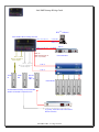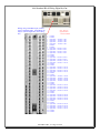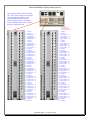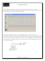
1
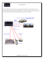
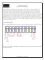
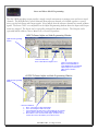
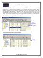
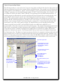
S A S 3 2 KD
A
AU
UD
DIIO
O RRO
OU
UTTIIN
NG
GN
NEETTW
WO
ORRK
K
IInnssttaallllaattiioonn aanndd UUsseerr MMaannuuaall
Proprietary Notice
This document contains proprietary information which may not be disclosed to others or used in manufacturing, or any other
purpose, without written permission from Sierra Automated Systems & Engineering Corporation. The information and design
disclosed herein were originated by and are the property of Sierra Automated Systems & Engineering Corporation. All patent,
proprietary design, manufacturing, reproduction, use and sales rights are reserved except where those rights are expressly granted
to others.
Copyright Notice
Copyright 1999 by Sierra Automated Systems & Engineering Corporation, Burbank, California, USA. All rights reserved.
Reproduction in whole or in part without prior written permission from Sierra Automated Systems & Engineering Corporation is
prohibited.
Service Manual for SAS 32KD Stereo Audio Routing Switcher
Revision: 1
This manual is published by the Engineering Department of Sierra Automated Systems & Engineering Corporation, which is
responsible for its contents. Address all communication regarding this publication to:
Director of Engineering
Sierra Automated Systems & Engineering Corporation
2821 Burton Avenue
Burbank, California 91504
USA
Tel (818) 840-6749 Fax (818) 840-6751 www.sasaudio.com
Limited Warranty
The products of Sierra Automated Systems & Engineering Corporation are warranted to be free from defects in materials and
workmanship for a period of one year from the date of sale.
Sierra Automated Systems & Engineering Corporations sole obligation during the warranty period is to provide, without charge,
parts and labor necessary to remedy covered defects appearing in products returned prepaid to Sierra Automated Systems &
Engineering Corporation, 2625 North San Fernando Road., Burbank, California, 91504, U.S.A.. This warranty does not cover any
defect, malfunction or failure caused beyond the control of Sierra Automated Systems & Engineering Corporation, including
unreasonable or negligent operation, abuse, accident, failure to follow instructions in the Technical Manual or the Owner's Manual,
defective or improper associated equipment, attempts at modification and repair not authorized by Sierra Automated Systems &
Engineering Corporation, and shipping damage. Products with their serial numbers removed or effaced are not covered by this
warranty.
This warranty is the sole and exclusive express warranty given with respect to Sierra Automated Systems & Engineering
Corporation products. It is the responsibility of the user to determine before purchase that this product is suitable for the user's
intended purpose.
ANY AND ALL IMPLIED WARRANTIES, INCLUDING THE IMPLIED WARRANTY OF MERCHANTABILITY ARE
LIMITED TO THE DURATION OF THIS EXPRESS LIMITED WARRANTY.
SIERRA AUTOMATED SYSTEMS & ENGINEERING CORPORATION IS NOT LIABLE FOR INCIDENTAL OR
CONSEQUENTIAL DAMAGES OF ANY KIND.
SAS32KD / REV 1.8 / Page 2 of 40
SAS 32KD Audio Routing Network
Table of Contents.
Description ......................................................................................................................................................... 4
Main Frame Description .................................................................................................................................................................. 4
User Connection Modules................................................................................................................................................................ 5
Connecting the Router Control Software Computer (RCS computer) ............................................................................................. 5
KAI-16 Analog Input Module Description ...................................................................................................................................... 6
KDI-16 Digital Input Module Description....................................................................................................................................... 7
KAO-16 Analog Output Module Description .................................................................................................................................. 8
KDO-16 AES Output Module Description ...................................................................................................................................... 9
KRL-16 RIO Link Module Description ......................................................................................................................................... 10
RIO Link Chassis Description ....................................................................................................................................................... 11
DRC-16 Serial Control Port Description. ...................................................................................................................................... 11
RIO Chassis Analog Signal Connector Terminal/Pin Assignment (Input and Output) ................................................................. 12
RIO Chassis Digital (AES) Signal Connector Terminal/Pin Assignment (Input and Output) ....................................................... 13
RIO Chassis RS-485 Control Port Connector Terminal/Pin Assignment ...................................................................................... 14
RIO Chassis Relay Connector Terminal/Pin Assignment.............................................................................................................. 15
RIO Chassis Opto Isolated Inputs Connector Terminal/Pin Assignment....................................................................................... 16
EURO Connector Pin Detail for Analog I/O.................................................................................................................................. 17
EURO Connector Pin Detail for Digital I/O .................................................................................................................................. 18
EURO Connector Pin Detail for RS-485 Ports .............................................................................................................................. 19
EURO Connector Pin Detail for MCU-32E................................................................................................................................... 20
Typical Application........................................................................................................................................................................ 21
SAS 32KD Startup Wiring Guide.................................................................................................................... 22
SAS Standard Block Wiring Digital In/Out. .................................................................................................................................. 23
SAS Standard Block Wiring Analog In/Out. ................................................................................................................................. 24
External AES/Clock Input .............................................................................................................................. 25
Typical Configuration ..................................................................................................................................... 26
Frame Module Installation. ............................................................................................................................................................ 26
Stereo and Mono Mode Programming. .......................................................................................................................................... 27
INPUT Channel Alpha and Link Programming Window. ............................................................................................................. 27
OUTPUT Channel Alpha and Link Programming Window. ......................................................................................................... 27
Stereo and Mono Mode Programming. .......................................................................................................... 28
Typical Configuration Example for Destination Channels. ........................................................................................................... 28
Typical Configuration Example for Source Channels.................................................................................................................... 28
Typical Crosspoint Map Display. .................................................................................................................................................. 29
SAS Control Panel Wiring Detail ................................................................................................................... 30
SAS Control PanelConfiguration/Assignment............................................................................................................................... 31
SAS Control Panel Configuration Expanded Addressing (to 8 ) ................................................................................................... 32
GPI 1600 Opto/Relay Control Panel............................................................................................................... 33
Connecting the GPI-1600............................................................................................................................................................... 33
GPI-1600 Opto/Relay Programming.............................................................................................................................................. 34
Intercom and IFB Feature.............................................................................................................................. 36
RCS-16 Control Panel Wiring ....................................................................................................................................................... 36
APC-88 Control Panel Wiring for Intercom ................................................................................................................................. 37
Intercom Station Programming ...................................................................................................................................................... 38
Button Templates and Programming.............................................................................................................................................. 39
SAS32KD / REV 1.8 / Page 3 of 40
SAS 32KD Digital Audio Network
PRELIMINARY
Description
The SAS 32KD is large scale digital audio network switching system housed in a 6 rack unit frame that
contains all audio signal modules, frame controller and multi-port RS-485 controller modules. The system
provides dual backup power supplies with separate AC line cords to allow a greater level of redundancy. The
frame is universal in that any slot can be fitted with audio input modules, audio output modules and required
controller modules. The frame provides up to 512 audio signal connections using a passive connector module
installed from the rear of the frame. The connector module contains no electronic components and a variety
of connector types can be optionally selected for audio inputs, outputs and controllers. The connector
modules are available with EURO (32 analog signal SAS standard connector), RJ21/45 (RJ-21 - 50 pin telco
ribbon for 16 signal circuits plus RJ-45 for Ethernet or RS-232/485), and dual DB25 (computer D sub, 8 signal
circuits each, 16 circuits total).
The frame can be populated with any compliment of audio input modules (analog or digital), audio output
modules (analog or digital), and required number of RS-485 control ports suitable for connection to all SAS
standard alphanumeric/pushbutton router or intercom control panels.
The modular audio signal modules are available in analog or digital as follows:
KAI-16 provides 16 stereo analog audio inputs
KAO-16 provides 16 stereo analog outputs
KDI-16 provides 16 AES/EBU inputs
KDO-16 provides 16 AES/EBU outputs
The system allows any combination of inputs sources to be mapped (switched or mixed) to any output. The
system provides many control options ranging from front panel manual selection using a wide variety of alpha
numeric control panels, to full automation using the SAS Routing Control Software or automation serial
control ports. The system provides summing and mixing of audio sources to any output suitable for building
mix minus feeds and other mixing applications.
Main Frame Description
The Frame provides 21 universal slots. For ease of documentation and comprehension, especially in multiframe systems, SAS recommends reserving the leftmost slots 1 to 16 for audio or other signal I/O modules and
the rightmost 5 slots 17 to 21 for control and network modules: Frame Controllers, Remote Control Modules,
and Audio Network Interface. The system requires at least 1 MCU-32 Frame controller which supplies system
clock on two separate clock busses. An optional second MCU-32 module can be installed and will
automatically provide backup system clock and other communication functions for greater redundancy. A and
B clock busses provide an additional level of fault tolerance - if the integrity of the clock bus is uncertain, each
module will automatically switch to the alternate clock bus.
SAS32KD / REV 1.8 / Page 4 of 40
User Connection Modules
User Connection Modules allow signal connections to the mainframe. A connection module is installed into
the rear of the frame for each audio module (input or output) and controller module. The connection module
does not contain active or passive electronic components which eliminates the need for servicing once
installed. Analog signal modules require the EURO connector module which provides 32 audio signal
connections (16 Stereo analog), while the digital signal modules can optionally be fitted with EURO connector
modules (upper 16 signals used only) or RJ21 connector modules (25 pair telco ribbon provides 16 signal and
8 ground pairs).
Connecting the Router Control Software Computer (RCS computer)
The system is configured using the RCS win software provided on CD ROM with the system. The computer is
for configuration only and is not required for the system to operate. System programming such as source and
destination names, serial RS-485 port assignments and push button programming is accomplished using the
RCS software. The complete mapping and all system configuration programming is stored in non-volatile
memory on board the MCU-32 Frame Controller module and will be automatically restored after any power
disruption.
Computer RS-232 Port
MCU-32 EURO Connector
C3 (RS-232 Tx) ------------------------------------------------------------------------------------- Pin 2 DB 9 Rx / Pin 3 DB 25 Rx
B3 (RS-232 Rx) ------------------------------------------------------------------------------------- Pin 3 DB 9 Tx / Pin 2 DB 25 Tx
A3 (RS-232 Gnd) --------------------------------------------------------------------------------- Pin 5 DB 9 Gnd/ Pin 7 DB 25 Gnd
The software will query the system and learn the type of module that has been installed in the frame. The
software will chronologically assign input and output channel numbers if desired, or the channels may be
assigned and locked down manually at any time. Once set up, (and inputs and outputs are wired accordingly),
this configuration is stored and will not have to be modified until the system grows.
For quick startup wiring information refer to page 20.
SAS32KD / REV 1.8 / Page 5 of 40
SAS 32KD
Front View
Rear View
KAI-16 Analog Input Module Description
The KAI-16 Analog Input Module provides 16 Stereo Audio Inputs (32 mono channels) into the system. The
module digitizes signals using full linear 24 bit A/D conversion at 48K sampling rate. Each module feeds a 32
channel TDM serial buss which corresponds to the frame slot. This allows hot swap-ability without disrupting
audio signals from other modules within the system.
KAI-16
32 Ch. Input Module
KAI-16
Block Diagram
Analog In 1
32 ch TDM
Audio Ch. 1
Audio Ch. 2
Audio Ch. 32
A/D’s
(32)
32 x 1
Mux
Clock A
Clock B
Analog In 32
Clock A/B
User Connector Module
Microprocessor
Serial Control Ports
Back plane
SAS32KD / REV 1.8 / Page 6 of 40
SAS 32KD
Front View
Rear View
KDI-16 Digital Input Module Description
The KDI-16 Digital Input Module provides 16 AES/EBU Inputs (32 mono channels) into the system. The
module receives the AES encoded audio data and separates it into 2 individual channels. A high performance
sample rate converter re-clocks the data into an internally timed bitstream and then is encoded onto a single 32
channel TDM serial bus. Each module feeds a 32 channel TDM serial buss which corresponds to the frame
slot. This allows hot swap-ability without disrupting audio signals from other modules within the system.
KDI-16
16 AES/EBU Inputs
KDI-16
Block Diagram
User Inputs
AES 1
AES 1 In
AES 16 In
AES 16
32 ch TDM
AES
Receivers and
SRC
32 x 1
Mux
Clock A
Clock B
Clock A/B
User Connector Module
Microprocessor
Serial Control Ports
Back plane
SAS32KD / REV 1.8 / Page 7 of 40
KAO-16 Analog Output Module Description
The KAO-16 Analog Output module provides 16 Stereo Audio Outputs (32 mono channels) from the system.
The module provides selection of 32 channels from the 1024 channels on the backplane: 16 serial 32 channel
TDM busses of internal sources (512 total possible from input modules within the frame) and 16 serial 32
channel TDM busses of sources that are received from external frames through the Audio Network Interface
module (512 total possible from network modules for multi-frame systems). The KAO-16 utilizes full 24 bit
linear D/A conversion that provides a nominal 110 dB dynamic range. An on-board DSP processor allows
functions such as mixing and level control to 32 additional outputs that are re-entered into the frame on the
slots corresponding TDM input bus. This allows processed audio to be available to other outputs within the
system, in addition to the outputs on the module for customized applications.
KAO-16
32 Ch. Output Module
KAO-16
Block Diagram
User Outputs
Back plane
16, 32Ch. TDM Busses
Internal TDM From Slot 1 (32 ch.TDM)
Analog Outputs
1 to 32
1024
De-Mux
Internal TDM From Slot 16 (32 ch.TDM)
32
D/A’s
32 Channels
External
512 Ch. TDM
(NIC Module)
1024x128
128 Ch.
Microprocessor
DSP
32 Ch. TDM
Back plane
(Feeds Slot 1 to 16)
SAS32KD / REV 1.8 / Page 8 of 40
KDO-16 AES Output Module Description
The KDO-16 Digital AES Output module provides 16 Stereo AES Outputs (32 mono channels) from the
system. The module provides selection of 32 channels from the 1024 channels on the backplane: 16 serial 32
channel TDM busses of internal sources (512 total possible from input modules within the frame) and 16
serial 32 channel TDM busses of sources that are received from external frames through the Audio Network
Interface module (512 total possible from network modules for multi-frame systems). The KDO-16 allows any
2 input channels to be mapped to the A and B channels of the AES data signal to allow a 2 channel mono or
Left and Right Stereo.
KDO-16
32 Ch. Output Module
KDO-16
Block Diagram
User Outputs
Back plane
16, 32Ch. TDM Busses
Internal TDM From Slot 1 (32 ch.TDM)
AES Outputs
1 to 16
1024
De-Mux
Internal TDM From Slot 16 (32 ch.TDM)
32
AES Drivers
32 Channels
External
512 Ch. TDM
(NIC Module)
1024x128
128 Ch.
Microprocessor
DSP
32 Ch. TDM
Back plane
(Feeds Slot 1 to 16)
SAS32KD / REV 1.8 / Page 9 of 40
KRL-16 RIO Link Module Description
The KRL-16 module provides 32 channels into the system and 32 channels out. The IO module allows a 32
channel multi-audio signal, and 16 RS-485 standard SAS control channels to be delivered “to and from” a RIO
Link Chassis across a CAT V or Fiber connection. The RIO Link Chassis is a 2 RU self-contained interface
that is suitable to be installed into a control room, studio or other remote location and utilizes RJ-21 (50 pin
telephone type) connectors for signal interconnection. A standard telephone type CAT V cable terminated
with 50 RJ-21 connectors can be used to quickly wire to a punch block with an RJ-21 connector (option)
installed on the side. A corresponding RIO connector module is installed into the rear of the frame that
houses an RJ45 standard CATV connector and an optional fiber plug in element. When using CAT V
cabling, the fiber elements must not be installed.
KRL-16
32 Ch. Input/Output module
KRL-16
Block Diagram
Back plane
16, 32Ch. TDM Busses
Internal TDM From Slot 1 (32 ch.TDM)
Internal TDM From Slot 16 (32 ch.TDM)
1024
De-Mux
32 Ch.
Mux
Mux
Tx
De-Mux
Rx
External
512 Ch. TDM
(NIC Module)
RJ-45 (CAT V)
To RIO Link Chassis
(RIO Connector Module
1024x128
128 Ch.
Microprocessor
DSP
32 Ch. TDM
Back plane
(Feeds Slot 1 to 16)
SAS32KD / REV 1.8 / Page 10 of 40
RIO Link Chassis Description
The RIO Link Chassis is a 2 RU chassis that can be remotely located up to 600 feet using CAT V standard
network (LAN) cable, or longer using the fiber option. The fiber option are plug in connector elements that
install into the rear of the mainframe, and chassis. The chassis connects to the mainframe as shown below.
“LINK” indicator LED’s on the front of the KRL-16 mainframe module and front of the RIO Link Chassis
will turn to green (from Red) when the link (CAT V or Fiber) connection is established.
Front
View
Rear
View
CAT V
Or Fiber
Signal.
In 17-32
RS-485 Serial
Control Ports
(Similar to DRC-16)
RJ21 50 Pin Connectors
Signal
In 1-16
Signal
Out 17-32
Signal
Out 1-16
Audio inputs and outputs are connected to the remote RIO Link chassis utilizing standard RJ-21 telephone
type connectors. Each connector provides 16 channels of audio and can optionally be fitted with analog or
digital interconnect modules. Any combination of digital/analog inputs and outputs is allowed. When the
chassis is fitted with a digital I/O type connector module only the first eight (8) signal connections are used.
A standard 50 pin (25 pair) CAT V telephone cable can be used to connect directly to a punch block housing
a 50 pin connector on the side. The terminal pin out of the block is as follows.
DRC-16 Serial Control Port Description.
The DRC-16 module for the SAS 32KD is a controller module that provides 16 RS-485 serial ports and 5 RS232 serial ports. The RS-485 ports can be configured individually to allow operation from XY or SOC (single
output control) type SAS alpha numeric controllers or AUTOMATION, or connection to GPI-1600 relay
controllers, and Intercom full function control panels. Each RS-485 port can be programmed to allow up to 4
controllers of the same type (i.e. XY, SOC, Intercom) utilizing an addressing technique. The address of each
individual control panel is determined by a jumper on the System RS-485 DB9 mating connector. Utilizing
address pins on the mating connector allows controller plug and play interchange-ability without having to set
switches or jumpers on the controller hardware itself. The 5 RS-232 serial ports are configured for standard
USI (user serial interface) protocol suitable for connection to digital audio delivery systems, or other
automation type computers.
SAS32KD / REV 1.8 / Page 11 of 40
RIO Chassis Analog Signal Connector Terminal/Pin Assignment (Input and Output)
The RIO Chassis connector for Analog Signals is designed to connect directly to a standard 50 pin terminal
block such as the 66 or Krone that has an RJ21 connector option. Utilizing off the shelf telephone CAT V,
and telephone block, the terminal block pin detail is as follows.
Standard Punch Block with
50 Pin RJ21 on the Side.
1 - Common
2 - Common
3 - Signal Audio + RIO Channel 1 or 17
4 - Signal Audio - RIO Channel 1 or 17
5 - Signal Audio + RIO Channel 2 or 18
6 - Signal Audio - RIO Channel 2 or 18
7 - Common
8 - Common
9 - Signal Audio + RIO Channel 3 or 19
10 - Signal Audio - RIO Channel 3 or 19
11 - Signal Audio + RIO Channel 4 or 20
12 - Signal Audio - RIO Channel 4 or 20
13 - Common
14 - Common
15 - Signal Audio + RIO Channel 5 or 21
16 - Signal Audio - RIO Channel 5 or 21
17 - Signal Audio + RIO Channel 6 or 22
18 - Signal Audio - RIO Channel 6 or 22
19 - Common
20 - Common
21 - Signal Audio + RIO Channel 7 or 23
22 - Signal Audio - RIO Channel 7 or 23
23 - Signal Audio + RIO Channel 8 or 24
24 - Signal Audio - RIO Channel 8 or 24
25 - Common
26 - Common
27 - Signal Audio + RIO Channel 9 or 25
28 - Signal Audio - RIO Channel 9 or 25
29 - Signal Audio + RIO Channel 10 or 26
30 - Signal Audio - RIO Channel 10 or 26
31 - Common
32 - Common
33 - Signal Audio + RIO Channel 11 or 27
34 - Signal Audio - RIO Channel 11 or 27
35 - Signal Audio + RIO Channel 12 or 28
36 - Signal Audio - RIO Channel 12 or 28
37 - Common
38 - Common
39 - Signal Audio + RIO Channel 13 or 29
40 - Signal Audio - RIO Channel 13 or 29
41 - Signal Audio + RIO Channel 14 or 30
42 - Signal Audio - RIO Channel 14 or 30
43 - Common
44 - Common
45 - Signal Audio + RIO Channel 15 or 31
56 - Signal Audio - RIO Channel 15 or 31
57 - Signal Audio + RIO Channel 16 or 32
48 - Signal Audio - RIO Channel 16 or 32
49 - Common
50 - Common
For Connector 1-16 For Connector 17-32
SAS32KD / REV 1.8 / Page 12 of 40
RIO Chassis Digital (AES) Signal Connector Terminal/Pin Assignment (Input and Output)
The RIO Chassis connector for AES digital I/O is designed to connect directly to a standard 50 pin terminal
block such as the 66 or Krone that has an RJ21 connector option. Utilizing off the shelf telephone CAT V,
and telephone block, the terminal block pin detail is as follows.
Standard Punch Block with
50 Pin RJ21 on the Side.
1 - Common
2 - Common
3 - Signal AES + RIO Channel 1 and 2 or 17 and 18
4 - Signal AES - RIO Channel 1 and 2 or 17 and 18
5 - Signal AES + RIO Channel 3 and 4 or 19 and 20
6 - Signal AES - RIO Channel 3 and 4 or 19 and 20
7 - Common
8 - Common
9 - Signal AES + RIO Channel 5 and 6 or 21 and 22
10 - Signal AES - RIO Channel 5 and 6 or 21 and 22
11 - Signal AES + RIO Channel 7 and 8 or 23 and 24
12 - Signal AES - RIO Channel 7 and 8 or 23 and 24
13 - Common
14 - Common
15 - Signal AES + RIO Channel 9 and 10 or 25 and 26
16 - Signal AES - RIO Channel 9 and 10 or 25 and 26
17 - Signal AES + RIO Channel 11 and 12 or 27 and 28
18 - Signal AES - RIO Channel 11 and 12 or 27 and 28
19 - Common
20 - Common
21 - Signal AES + RIO Channel 13 and 14 or 29 and 30
22 - Signal AES - RIO Channel 13 and 14 or 29 and 30
23 - Signal AES + RIO Channel 15 and 16 or 31 and 32
24 - Signal AES - RIO Channel 15 and 16 or 31 and 32
25 - Common
26 - Common
27 28 29 –
30 31 32 For Connector 1-16 For Connector 17-32
33 34 35 36 37 38 39 40 41 42 43 44 45 56 57 48 49 50 -
SAS32KD / REV 1.8 / Page 13 of 40
RIO Chassis RS-485 Control Port Connector Terminal/Pin Assignment
The RIO Chassis connector for RS485 control ports is designed to connect directly to a standard 50 pin
terminal block such as the 66 or Krone that has an RJ21 connector option. Utilizing off the shelf telephone
CAT V, and telephone block, the terminal block pin detail is as follows.
Standard Punch Block with
50 Pin RJ21 on the Side.
1 - Common
2 - Common
3 - RS485 Port
4 - RS485 Port
5 - RS485 Port
6 - RS485 Port
7 - Common
8 - Common
9 - RS485 Port
10 - RS485 Port
11 - RS485 Port
12 - RS485 Port
13 - Common
14 - Common
15 - RS485 Port
16 - RS485 Port
17 - RS485 Port
18 - RS485 Port
19 - Common
20 - Common
21 - RS485 Port
22 - RS485 Port
23 - RS485 Port
24 - RS485 Port
25 - Common
26 - Common
27 - RS485 Port
28 - RS485 Port
29 - RS485 Port
30 - RS485 Port
31 - Common
32 - Common
33 - RS485 Port
34 - RS485 Port
35 - RS485 Port
36 - RS485 Port
37 - Common
38 - Common
39 - RS485 Port
40 - RS485 Port
41 - RS485 Port
42 - RS485 Port
43 - Common
44 - Common
45 - RS485 Port
56 - RS485 Port
57 - RS485 Port
48 - RS485 Port
49 - Common
50 - Common
SAS32KD / REV 1.8 / Page 14 of 40
+
+
-
1
1
2
2
+3
- 3
+4
-4
+5
- 5
+6
-6
+7
-7
+8
-8
+9
-9
+ 10
- 10
+ 11
- 11
+ 12
- 12
+ 13
- 13
+ 14
- 14
+ 15
- 15
+ 16
- 16
RIO Chassis Relay Connector Terminal/Pin Assignment
The RIO Chassis connector relays are designed to connect directly to a standard 50 pin terminal block such as
the 66 or Krone that has an RJ21 connector option. The relays are solid state and use a mutual conductance
type of topology. The relays have a plus and minus polarity and although the relay uses the mutual
conductance of a FET it is still recommended to connect the relay output with the correct polarity. Utilizing
off the shelf telephone CAT V, and telephone block, the terminal block pin detail is as follows.
Standard Punch Block with
50 Pin RJ21 on the Side.
1 - Common
2 - Common
3 - Relay 1 + (or normally open)
4 - Relay 1 com
5 - Relay 2 + (or normally open)
6 - Relay 2 com
7 - Common
8 - Common
9 - Relay 3 + (or normally open)
10 - Relay 3 com
11 - Relay 4 + (or normally open)
12 - Relay 4 com
13 - Common
14 - Common
15 - Relay 5 + (or normally open)
16 - Relay 5 com
17 - Relay 6 + (or normally open)
18 - Relay 6 com
19 - Common
20 - Common
21 - Relay 7 + (or normally open)
22 - Relay 7 com
23 - Relay 8 + (or normally open)
24 - Relay 8 com
25 - Common
26 - Common
27 - Relay 9 + (or normally open)
28 - Relay 9 com
29 - Relay 10 + (or normally open)
30 - Relay 10 com
31 - Common
32 - Common
33 - Relay 11 + (or normally open)
34 - Relay 11 com
35 - Relay 12 + (or normally open)
36 - Relay 12 com
37 - Common
38 - Common
39 - Relay 13 + (or normally open)
40 - Relay 13 com
41 - Relay 14 + (or normally open)
42 - Relay 14 com
43 - Common
44 - Common
45 - Relay 15 + (or normally open)
56 - Relay 15 com
57 - Relay 16 + (or normally open)
48 - Relay 16 com
49 - Common
50 - Common
SAS32KD / REV 1.8 / Page 15 of 40
RIO Chassis Opto Isolated Inputs Connector Terminal/Pin Assignment
The RIO Chassis connector Optically Isolated Inputs are designed to connect directly to a standard 50 pin
terminal block such as the 66 or Krone that has an RJ21 connector option. The optical isolators are internally
current limiting and can be connected directly to a DC control line from 5 to 15 volts. The LED’s on the
Optical section draws between 1 mA at 5 volts to 6 mA at 15 volts. The connector also provides an internal
fused 5 volts that can be used as a B+ common for connection and control from a dry contact switch. It is
always recommended to feed the Common (or negative) through the dry contact to the Gnd. Utilizing off the
shelf telephone CAT V, and telephone block, the terminal block pin detail is as follows.
Standard Punch Block with
50 Pin RJ21 on the Side.
1 - + 5 Volts
2 - GND
3 - Opto (LED)
4 - Opto (LED)
5 - Opto (LED)
6 - Opto (LED)
7 - + 5 Volts
8 - GND
9 - Opto (LED)
10 - Opto (LED)
11 - Opto (LED)
12 - Opto (LED)
13 - + 5 Volts
14 - GND
15 - Opto (LED)
16 - Opto (LED)
17 - Opto (LED)
18 - Opto (LED)
19 - + 5 Volts
20 - GND
21 - Opto (LED)
22 - Opto (LED)
23 - Opto (LED)
24 - Opto (LED)
25 - + 5 Volts
26 - GND
27 - Opto (LED)
28 - Opto (LED)
29 - Opto (LED)
30 - Opto (LED)
31 - + 5 Volts
32 - GND
33 - Opto (LED)
34 - Opto (LED)
35 - Opto (LED)
36 - Opto (LED)
37 - + 5 Volts
38 - GND
39 - Opto (LED)
40 - Opto (LED)
41 - Opto (LED)
42 - Opto (LED)
43 - + 5 Volts
44 - GND
45 - Opto (LED)
56 - Opto (LED)
57 - Opto (LED)
48 - Opto (LED)
49 - + 5 Volts
50 - GND
SAS32KD / REV 1.8 / Page 16 of 40
1+
1 - (Gnd)
2+
2 - (Gnd)
3+
3 - (Gnd)
4+
4 - (Gnd)
5+
5 - (Gnd)
6+
6 - (Gnd)
7+
7 - (Gnd)
8+
8 - (Gnd)
9+
9 - (Gnd)
10 +
10 - (Gnd)
11 +
11 - (Gnd)
12 +
12 - (Gnd)
13 +
13 - (Gnd)
14 +
14 - (Gnd)
15 +
15 - (Gnd)
16 +
16 - (Gnd)
EURO Connector Pin Detail for Analog I/O
(For KAI-16 and KAO-16 Analog Modules)
C
Rear View
(Rear of Frame)
1
2
3
B
Sig 1 +
1
Sig 2 +
2
A
Sig 1 -
1
Sig 1 Gnd
Sig 2 -
2
Sig 2 Gnd
Sig 3 Gnd
Sig 3 +
3
Sig 3 -
3
4
Sig 4 +
4
Sig 4 -
4
Sig 4 Gnd
5
Sig 5 +
5
Sig 5 -
5
Sig 5 Gnd
6
Sig 6 +
6
Sig 6 -
6
Sig 6 Gnd
7
Sig 7 +
7
Sig 7 -
7
Sig 7 Gnd
8
Sig 8 +
8
Sig 8 -
8
Sig 8 Gnd
9
Sig 9 +
9
Sig 9 -
9
Sig 9 Gnd
10
Sig 10 +
10
Sig 10 -
10
Sig 10 Gnd
11
Sig 11 +
11
Sig 11 -
11
Sig 11 Gnd
12
Sig 12 +
12
Sig 12 -
12
Sig 12 Gnd
13
Sig 13 +
13
Sig 13 -
13
Sig 13 Gnd
14
Sig 14 +
14
Sig 14 -
14
Sig 14 Gnd
15
Sig 15 +
15
Sig 15 -
15
Sig 15 Gnd
16
Sig 16 +
16
Sig 16 -
16
Sig 16 Gnd
17
Sig 17 +
17
Sig 17 -
17
Sig 17 Gnd
18
Sig 18 +
18
Sig 18 -
18
Sig 18 Gnd
19
Sig 19 +
19
Sig 19 -
19
Sig 19 Gnd
20
Sig 20 +
20
Sig 20 -
20
Sig 20 Gnd
21
Sig 21 +
21
Sig 21 -
21
Sig 21 Gnd
22
Sig 22 +
22
Sig 22 -
22
Sig 22 Gnd
23
Sig 23 +
23
Sig 23 -
23
Sig 23 Gnd
24
Sig 24 +
24
Sig 1 -
24
Sig 24 Gnd
25
Sig 25 +
25
Sig 25 -
25
Sig 25 Gnd
26
Sig 26 +
26
Sig 26 -
26
Sig 26 Gnd
27
Sig 27 +
27
Sig 27 -
27
Sig 27 Gnd
28
Sig 28 +
28
Sig 28 -
28
Sig 28 Gnd
29
Sig 29 +
29
Sig 29 -
29
Sig 29 Gnd
30
Sig 30 +
30
Sig 30 -
30
Sig 30 Gnd
31
Sig 31 +
31
Sig 31 -
32
Sig 31 Gnd
32
Sig 32 +
32
Sig 32 -
32
Sig 32 Gnd
SAS32KD / REV 1.8 / Page 17 of 40
EURO Connector Pin Detail for Digital I/O
(For KDI-16 and KDO-16 Digital Modules)
C
Rear View
(Rear of Frame)
A
B
1
Sig 1 +
1
Sig 1 -
1
Sig 1 Gnd
2
Sig 2 +
2
Sig 2 -
2
Sig 2 Gnd
3
Sig 3 +
3
Sig 3 -
3
Sig 3 Gnd
4
Sig 4 +
4
Sig 4 -
4
Sig 4 Gnd
5
Sig 5 +
5
Sig 5 -
5
Sig 5 Gnd
6
Sig 6 +
6
Sig 6 -
6
Sig 6 Gnd
7
Sig 7 +
7
Sig 7 -
7
Sig 7 Gnd
8
Sig 8 +
8
Sig 8 -
8
Sig 8 Gnd
9
Sig 9 +
9
Sig 9 -
9
Sig 9 Gnd
10
Sig 10 +
10
Sig 10 -
10
Sig 10 Gnd
11
Sig 11 +
11
Sig 11 -
11
Sig 11 Gnd
12
Sig 12 +
12
Sig 12 -
12
Sig 12 Gnd
13
Sig 13 +
13
Sig 13 -
13
Sig 13 Gnd
14
Sig 14 +
14
Sig 14 -
14
Sig 14 Gnd
15
Sig 15 +
15
Sig 15 -
15
Sig 15 Gnd
16
Sig 16 +
16
Sig 16 -
16
Sig 16 Gnd
17
nc
17
nc
17
nc
18
nc
18
nc
18
nc
19
nc
19
nc
19
nc
20
nc
20
nc
20
nc
21
nc
21
nc
21
nc
22
nc
22
nc
22
nc
23
nc
23
nc
23
nc
24
nc
24
nc
24
nc
25
nc
25
nc
25
nc
26
nc
26
nc
26
nc
27
nc
27
nc
27
nc
28
nc
28
nc
28
nc
29
nc
29
nc
29
nc
30
nc
30
nc
30
nc
nc
31
nc
32
nc
nc
32
nc
32
nc
31
32
SAS32KD / REV 1.8 / Page 18 of 40
EURO Connector Pin Detail for RS-485 Ports
(For DRC-16 RS-485 Controller Module)
C
Rear View
(Rear of Frame)
B
A
1
Ctl 1 +
1
Ctl 1 -
1
Ctl 1 Gnd
2
Ctl 2 +
2
Ctl 2 -
2
Ctl 2 Gnd
3
Ctl 3 +
3
Ctl 3 -
3
Ctl 3 Gnd
4
Ctl 4 +
4
Ctl 4 -
4
Ctl 4 Gnd
5
Ctl 5 +
5
Ctl 5 -
5
Ctl 5 Gnd
6
Ctl 6 +
6
Ctl 6 -
6
Ctl 6 Gnd
7
Ctl 7 +
7
Ctl 7 -
7
Ctl 7 Gnd
8
Ctl 8 +
8
Ctl 8 -
8
Ctl 8 Gnd
9
Ctl 9 +
9
Ctl 9 -
9
Ctl 9 Gnd
10
Ctl 10 +
10
Ctl 10 -
10
Ctl 10 Gnd
11
Ctl 11 +
11
Ctl 11 -
11
Ctl 11 Gnd
12
Ctl 12 +
12
Ctl 12 -
12
Ctl 12 Gnd
13
Ctl 13 +
13
Ctl 13 -
13
Ctl 13 Gnd
14
Ctl 14 +
14
Ctl 14 -
14
Ctl 14 Gnd
15
Ctl 15 +
15
Ctl 15 -
15
Ctl 15 Gnd
16
Ctl 16 +
16
Ctl 16 -
16
Ctl 16 Gnd
17
USI 1Tx
17
USI 1 Rx 17
USI 1 Gnd
18
USI 2 Tx
18
USI 2 Rx 18
USI 2 Gnd
19
USI 3 Tx
19
USI 3 Rx 19
USI 3 Gnd
20
USI 4 Tx
20
USI 4 Rx 20
USI 4 Gnd
USI 5 Tx
21
USI 5 Rx
21
USI 5 Gnd
n/c
22
n/c
22
n/c
Enet Tx +
23
Enet Tx-
23
Enet Gnd
Enet Rx +
24
Enet Rx-
24
Enet Gnd
n/c
25
n/c
25
n/c
n/c
26
n/c
26
n/c
n/c
21
22
23
24
25
26
27
n/c
27
n/c
27
28
n/c
28
n/c
28
n/c
29
n/c
29
n/c
29
n/c
30
n/c
30
n/c
30
n/c
31
n/c
31
n/c
32
n/c
32
n/c
32
n/c
32
n/c
SAS32KD / REV 1.8 / Page 19 of 40
RS-485 Serial
Control Ports.
To Alpha Numeric
Control Panels
RS-232 Serial
Control Ports.
User Serial Interface
To Automation or
DAD
EURO Connector Pin Detail for MCU-32E
(For MCU-32E RS-485 and RS232 Serial Ports)
C
Rear View
(Rear of Frame)
B
A
1
RS-485+
1
RS-485-
1
Gnd – RS-485 Port 1
2
RS-485+
2
RS-485-
2
Gnd - RS-485 Port 2
3
RS-232 Tx
3
RS-232 Rx
3
Gnd - To RCS win Computer
4
4
4
5
5
5
6
6
6
7
7
7
8
8
8
9
9
9
10
10
10
11
11
11
12
12
12
13
13
13
14
14
14
15
15
15
16
16
16
17
17
17
18
18
18
19
19
19
20
20
20
21
21
21
22
22
22
23
23
23
24
24
24
25
25
25
26
26
26
27
27
27
28
28
28
29
29
29
30
30
30
31
31
32
32
32
32
SAS32KD / REV 1.8 / Page 20 of 40
No User Connections
Typical Application
The SAS 32KD Switching Network system is suitable for a Radio Broadcast facility distribution system.
Utilizing a variety of control options from fully automated to single output manual control, the system can
provide switching/mixing and Intercom (auto IFB), and is popular for configuring audio consoles routable
fader channels (remote faders) and automatically steering mix minus feeds for IFB.
INTERCOM / IFB Stations
SAS32KD Audio Switcher
Can Intercommunicate to Other
Panels and can IFB to Zephyrs
Audio for
Intercom
(Talk, Listen)
RS-485 to SAS Controllers
Zephyr 1A
Audio for Remotes (IFB)
DRC-16
RS-485 Control Ports
Audio Out (Speaker)
Audio In (Mic)
Audio For Routable Fader
Channels. (Remote Faders)
Control Room
A0
A1
See Wiring/Addressing
Detail
SAS32KD / REV 1.8 / Page 21 of 40
Zephyr 1B
SAS 32KD Startup Wiring Guide
RCS Win Software
SAS 32KD Audio Switching Network
MCU-32 (C3,B3,A3)
(Slot 21) *
DRC-16 (C1,B1,A1)
(Slot 19) *
COM PORT
DB9 (2,3,5)
DB25(3,2,7)
SYS RS485
(4,5,1)
KRL-16
Multi-channel I/O on
CAT V (or Fiber)
Slot 1 Slot 8
KAI-16 or KDI-16
Audio Inputs
Slot 9 Slot 16
KAO-16 or KDO-16
Audio Outputs
AXC-8
* Recommended
CAT V
CAT V
Audio
In
Audio
Out
RS-485
Ports
DRC-16
Punch Blocks
See Punch Block Wiring for SAS Standard
and Recommended Terminal Pin Outs.
Audio Inputs
Audio Outputs Control
Audio to Destination (Control Room)
(Typically, Audio Pair and Control Pair to
Remote location)
SAS32KD / REV 1.8 / Page 22 of 40
SAS Standard Block Wiring Digital In/Out.
Wiring using a standard 50 pin (25 Pair)
CAT V telephone cable. 50 Pin RJ21 can
only be used for digital I/O. (not Analog
I/O).
Note: These are
Signal Channels
1-32 of the Module.
1 - Common
2 - Common
3 - Signal AES
4 - Signal AES
5 - Signal AES
6 - Signal AES
7 - Common
8 - Common
9 - Signal AES
10 - Signal AES
11 - Signal AES
12 - Signal AES
13 - Common
14 - Common
15 - Signal AES
16 - Signal AES
17 - Signal AES
18 - Signal AES
19 - Common
20 - Common
21 - Signal AES
22 - Signal AES
23 - Signal AES
24 - Signal AES
25 - Common
26 - Common
27 - Signal AES
28 - Signal AES
29 - Signal AES
30 - Signal AES
31 - Common
32 - Common
33 - Signal AES
34 - Signal AES
35 - Signal AES
36 - Signal AES
37 - Common
38 - Common
39 - Signal AES
40 - Signal AES
41 - Signal AES
42 - Signal AES
43 - Common
44 - Common
45 - Signal AES
46 - Signal AES
47 - Signal AES
48 - Signal AES
49 - Common
50 - Common
+
+
-
Channel
Channel
Channel
Channel
1 and 2
1 and 2
3 and 4
3 and 4
+ Channel
- Channel
+ Channel
- Channel
5 and 6
5 and 6
7 and 8
7 and 8
+ Channel
- Channel
+ Channel
- Channel
9 and 10
9 and 10
11 and 12
11 and 12
+ Channel
- Channel
+ Channel
- Channel
13 and 14
13 and 14
15 and 16
15 and 16
+
+
-
Channel
Channel
Channel
Channel
17 and 18
17 and 18
19 and 20
19 and 20
+ Channel
- Channel
+ Channel
- Channel
21 and 22
21 and 22
23 and 24
23 and 24
+ Channel
- Channel
+ Channel
- Channel
25 and 26
25 and 26
27 and 28
27 and 28
+ Channel
- Channel
+ Channel
- Channel
29 and 30
29 and 30
31 and 32
31 and 32
SAS32KD / REV 1.8 / Page 23 of 40
SAS Standard Block Wiring Analog In/Out.
Analog I/O uses EURO connector module
only. All 32 audio signal pairs are brought
out to punch blocks as follows. SAS
supplied/standard and Recommends
wiring to blocks as follows. Each Euro
Connector Module breaks out to 2 blocks
housing 16 signal pairs each.
Note: These are
Signal Channels
1-32 of the Module
1 - Common
2 - Common
3 - Signal Audio + 1
4 - Signal Audio - 1
5 - Signal Audio + 2
6 - Signal Audio - 2
7 - Common
8 - Common
9 - Signal Audio + 3
10 - Signal Audio - 3
11 - Signal Audio + 4
12 - Signal Audio - 4
13 - Common
14 - Common
15 - Signal Audio + 5
16 - Signal Audio - 5
17 - Signal Audio + 6
18 - Signal Audio - 6
19 - Common
20 - Common
21 - Signal Audio + 7
22 - Signal Audio - 7
23 - Signal Audio + 8
24 - Signal Audio - 8
25 - Common
26 - Common
27 - Signal Audio + 9
28 - Signal Audio - 9
29 - Signal Audio + 10
30 - Signal Audio - 10
31 - Common
32 - Common
33 - Signal Audio + 11
34 - Signal Audio - 11
35 - Signal Audio + 12
36 - Signal Audio - 12
37 - Common
38 - Common
39 - Signal Audio + 13
40 - Signal Audio - 13
41 - Signal Audio + 14
42 - Signal Audio - 14
43 - Common
44 - Common
45 - Signal Audio + 15
56 - Signal Audio - 15
57 - Signal Audio + 16
48 - Signal Audio - 16
49 - Common
50 - Common
SAS32KD / REV 1.8 / Page 24 of 40
1 - Common
2 - Common
3 - Signal Audio + 17
4 - Signal Audio - 17
5 - Signal Audio + 18
6 - Signal Audio - 18
7 - Common
8 - Common
9 - Signal Audio + 19
10 - Signal Audio - 19
11 - Signal Audio + 20
12 - Signal Audio - 20
13 - Common
14 - Common
15 - Signal Audio + 21
16 - Signal Audio - 21
17 - Signal Audio + 22
18 - Signal Audio - 22
19 - Common
20 - Common
21 - Signal Audio + 23
22 - Signal Audio - 23
23 - Signal Audio + 24
24 - Signal Audio - 24
25 - Common
26 - Common
27 - Signal Audio + 25
28 - Signal Audio - 25
29 - Signal Audio + 26
30 - Signal Audio - 26
31 - Common
32 - Common
33 - Signal Audio + 27
34 - Signal Audio - 27
35 - Signal Audio + 28
36 - Signal Audio - 28
37 - Common
38 - Common
39 - Signal Audio + 29
40 - Signal Audio - 29
41 - Signal Audio + 30
42 - Signal Audio - 30
43 - Common
44 - Common
45 - Signal Audio + 31
56 - Signal Audio - 31
57 - Signal Audio + 32
48 - Signal Audio - 32
49 - Common
50 - Common
External AES/Clock Input
The SAS 32KD switching network system provides a clock system internally. The internal clock rate is
selectable using the RCS windows software from the Switcher Status/Configuration main window. As shown
the internal default clock options are 32K, 44.1K, and 48K
The main frame additionally provides an external AES3/AES11 input for external clock reference.
Connecting and external clock to this input causes all outputs within the frame to be clock/frame synchronous
to the external reference clock. The software selectable system clock rate is ignored when a valid external clock
is detected. The rear of the frame provides a male 9 Pin D sub connector (DB9P) for external AES clock entry.
The clock signal can be an AES3 or AES11 (clock sync signal) which is a balanced differential signal requiring
3 pin connections as follows:
Pin 1 > Gnd (Shield)
Pin 2 > AES +
Pin 3 > AES -
DB9P (Female Cable End)
Rear Cable end View
SAS32KD / REV 1.8 / Page 25 of 40
Typical Configuration
SAS 32KD System Description
The SAS 32KD switching system for a typical application is configured for 64 analog audio inputs and 32
analog audio outputs, and 32 AES inputs and 32 AES Outputs. The system provides an audio switching
matrix function suitable for steering audio network feeds to various destinations using RS-232 automation
ports much like a conventional routing switcher. Digital and Analog domain crossovers are accomplished
automatically. The system can be controlled manually using the AXC-8 full system access XY control panel,
utilizing intuitive source and destination alpha numeric directories. Switcher I to O mapping is accomplished
by simply dialing up names in an alphabetically sorted list of source and destination names, and pressing the
“TAKE” button to execute the switch assignment. Serial control ports can be configured for automation to
allow automated operation. Additionally, the RCS WIN software, through standard IP protocol allows switching
control from a workstation computer across a LAN or WAN. The RCS WIN software also provides a folder for
automated switch mapping events.
Frame Module Installation.
The recommended module installation for a typical system is as follows, and is typically configured as follows:
1
2
3
4
5
6
7
K
R
L
1
6
K
R
L
1
6
K
D
O
1
6
K
D
O
1
6
K
A
O
1
6
K
A
O
1
6
K
A
O
1
6
6596
97- 129- 161- 193128 160 192 224
KDO= Digital Outputs
KAO= Analog Outputs
8
9
10
11
K
D
I
1
6
K
D
A
1
6
K
D
A
1
6
12
13
14
15
16
17
18
19
20
21
D
R
C
1
6
R
C
U
3
2
M
C
U
3
2
257- 289- 321288 320 352
KDI= Digital Inputs
KAI= Analog Inputs
To RIO
In 1-32
Out 1-32
Remote
Control
Frame
Controller
Redundant
Clock
To RIO
In 33-64
Out 33-64
Please refer to the addendum of this manual for information on the specific factory default module positions
for the delivered system.
SAS32KD / REV 1.8 / Page 26 of 40
Stereo and Mono Mode Programming.
The SAS 32KD switching system provides a simple control environment to manage stereo and mono signal
channels. The RCS (Router Control Software) allows adjacent channels to be linked together to create a
stereo pair for both Input and Output signals. If not linked, then the adjacent channels are treated as Mono
signals. The Stereo “link” is accomplished on the Alpha Programming window where the Input and Output
names are assigned. The Inputs can be optionally configured for Mono or Stereo. The Outputs can be
optionally linked as Mono, Stereo, Mono L+R, or Source Dependent.
INPUT Channel Alpha and Link Programming Window.
Alpha Labels Programming
Window.
1. Select from Pull Down
Stereo or Mono Mode for Inputs 1 and 2.
2.Input 1 is treated as LEFT Ch.
Input 2 is treated as RIGHT Ch.
Use the HIDE function on the RIGHT
Channel (Input 2) to remove from
Alpha numeric controllers
Directory.
OUTPUT Channel Alpha and Link Programming Window.
Alpha Labels Programming
Window.
1. Select from Pull Down
a.
Mono - treats Output as single channel Mono.
b. Stereo -treats Outputs 1 and 2 as Stereo pair.
c.
Source Dependant -If a mono source is selected then only Ch.1 changes.
If Stereo Source is selected, Ch.1 and Ch.2 (left and Right) changes.
d. Mono LR Sum- Ch.1 is treated as Mono Output. If a Stereo source is
selected, then Ch.1 is L+R divided by 2 (no 6 db rise in level).
SAS32KD / REV 1.8 / Page 27 of 40
Stereo and Mono Mode Programming.
Typically when the adjacent channels are linked as stereo pairs, the HIDE function is used to remove the Right
channel (source or destination) alpha label from the directory used by the alpha numeric controllers. (Since
the Right channel will always try to follow the Left channel as a stereo pair). Adjacent channels starting with
the ODD number only are allowed to be linked as stereo pairs. For example, Output channels 1 and 2 can be
linked as Stereo, NOT output Channels 2 and 3. If the actual signal output module is an AES digital output
module then the channel pair starting with the ODD channel number are grouped as the A and B segments
respectively. See notes below.
Typical Configuration Example for Destination Channels.
A
B
Mix Minus/IFB
PA Feed
AES Digital
OUT (Boundary)
AES Digital
OUT
Typical Configuration Example for Source Channels.
A
B
SAS32KD / REV 1.8 / Page 28 of 40
AES Digital
IN (Boundary)
Typical Crosspoint Map Display.
The following window is a view of what the Crosspoint map display would look like when the alpha names and
links are programmed as in the above example. (Source and Destination). This example is used to illustrate the
stereo and mono mode differences. Inputs 1 and 2 are linked as a stereo pair shown here with the alpha label
“CtlPgm1” appearing across the linked channel numbers “001,002”. (Stereo Boundary). Also, Outputs 1 and
2 are linked as a Stereo pair with it’s label “UPLink1” also appearing across the linked channel numbers. A
switcher mapping is indicated with a green dot and shows the input (column) that is currently selected to the
output (Row). In this example, inputs 1 and 2 (Ctl1 Pgm1 Stereo) is feeding outputs 1 and 2 (UPLink1
Stereo). The odd channels are treated as Stereo left (or AES A), and the even channels are treated as stereo
right (or AES B). Intuitively displayed, ch.1 (odd) is “Left” of Ch.2 (even). A two (2) channel codec is being
fed from a pair of outputs channel 5 and channel 6 and is configured as a 2 channel (mono) split feed. The
interconnect to the codec can be analog or digital. If a digital interface is used, remember that the ODD
channel is the AES A side or LEFT, and the EVEN Channel is the AES B side or RIGHT, so it is
recommended to adopt this convention early in the planning stages. The example shows that the Left (ch.5) or
AES A side is programmed as a Mono destination that is suitable for a Mix Minus feed (Ctl2 MM1) from the
Control Room console. Similarly, the Right (ch.6) or AES B side is programmed as a Mono LR Sum that
suitable for a PA feed at the remote. The B channel (OUT 6) has a mono sum of Ctl2 Pgm2 as shown with
the 2 (two) green dots. The Mono sum function performs a divide by 2 to maintain consistent audio levels and
will not result in the 5 to 6 db rise normally associated with mono Left plus Right summing. Similarly, codec
Zephyr 2 is setup to do a remote from Control room 1 where the Mix Minus from the control room is feeding
mono channel A (OUT 9) while the program 1 feed is L+R summed to channel B (out 10) for the PA feed.
Input Labels Appear Here.
Stereo Link Shows across the 2
Linked channels. Ch.1 is Left
and Ch.2 is Right. (Intuitively
as displayed)
Green dots indicate a selection of
An Input to the Output.
AES / STEREO Boundary
If AES Output, then
Ch.1 is Left, (A)
Ch.2 is Right (B)
Mono LR Sum Shown in
Different Shade.
Mono LR Sum indicated by these
2 dots.
Source Dependant Shown
In Different Shade.
Source Dependant will select to only
1 channel (ch.7) if the source is mono,
or to 2 channels (Ch.7 and Ch.8) if
the source is stereo.
AES Boundary
For Mono mode channels also.
SAS32KD / REV 1.8 / Page 29 of 40
SAS Control Panel Wiring Detail
All SAS alpha numeric Control Panels communicate to the system using an RS-485 serial port and connects
directly to a DCR-16 Multi port Module. Each Controller will allow source selection to a single output by
using an alphabetically sorted dial up directory displayed on an 8 character alpha numeric readout. A TAKE
Button is pressed to complete the switcher selection. Each RS-485 Serial control port is programmable to
allow up to two (2) SAS switcher controllers using a digital “Addressing” technique. All Controllers use a 9
Pin D sub (male) connector for interconnecting the RS485 serial port ( +,- Shield) to the corresponding DRC16 Serial RS-485 Port. If using multiple panels on a serial RS-485 port, the address strap is installed on the
cable end 9 Pin D-Sub (female that connects to the controller) allowing panel interchange-ability with out
having to deal with “addressing DIP or Jumper” settings. The address jumper for Console “Drop In” Series is
slightly different than the equivalent “Rack Mount” Series as shown below.
DRC-16 Connector
RS-485 Serial Ports
Rack Mount ANC-8 Series.
Panel Address 1
DRC-16 RS-485
(+ , - , Shld)
SYS RS485
DB9P Pin (4,5,1)
Jumper pin 2-6
Panel Address 0
(No Jumper)
AC Line In.
(IEC Line Chord)
SYS RS485
DB9P Pin (4,5,1)
ANC-8D (A side is A0, B side is A1)
DRC-16 RS-485
(+ , - , Shld)
SYS RS485
DB9P Pin (4,5,1)
No Jumper
Connect to RS-485 A Only
Console “Drop In” APC/CPI/CDS Series.
DRC-16 RS-485
(+ , - , Shld)
DB9P (Pins or Male) is the
connector on the Controller
Rear Panel. Cable end mating
connector is a DB9S (Sockets
or Female).
All Console “Drop In” series
Requires external 12v DC power
source. Wall Mount AC adapter is
supplied with mating connector.
Panel Address 1
SYS RS485
DB9P Pin (4,5,1)
Jumper pin 6-7
(3,2)
SYS RS485
DB9P Pin (4,5,1)
Panel Address 0
(3,2)
(No Jumper)
12v DC +,12v DC +,-
SAS32KD / REV 1.8 / Page 30 of 40
SAS Control PanelConfiguration/Assignment
The RCS (Router Control Software) is used to assign the Actual Switcher Output channel that each installed
Alpha Numeric controller is to direct. The frame will automatically learn the module that is installed into
each of the 21 slots, and if a DRC-16 is installed, the following window is used to configure the control ports
and assign the outputs for each of the controllers.
Window to Configure DRC-16 (16 RS-485 Serial Ports).
System learns DRC-16
Module is installed.
A0 and A1 Controllers
A0=no Jumper, A1= Jumper
On 9 pin D (see above)
Click Here to Configure
The control Ports.
Port 1 is XY (Full System Access Port.
Port 2,3,4 are ICM (Intercom) Port
Port 5-16 are SOC (Single Output Control) Port.
Use Scroll Bar to see Ports 12-16.
Select the Output
To be controlled.
Select Control Panel Type:
Single Output
Intercom
XY
Single Input Controller
Panel at A0 (no Jumper)
SAS32KD / REV 1.8 / Page 31 of 40
SAS Control Panel Configuration
Expanded Addressing (to 8 )
Optionally, the DRC-16 RS-485 control port module can be configured to address up to eight (8) SAS type
control panels. All rack mount type (ANC-8, ANC-8D and AXC-8) series panels only support two addresses
A0 and A1. The console drop in type, and rack mount type APC-88 and CDS-8 series will support all eight (8)
addresses. Additionally, the RCS-16 and DCS-16 intercom stations support all eight (8) addresses as well. The
table below shows the connector pin jumpers for the expanded eight address operation. The active addresses
each port can be set using the RCS win routers control software configuration screen for the DRC-16 module.
Click here to set number of panel
Addresses for each port on this module (16)
Window to Configure DRC-16 (16 RS-485 Serial Ports).
APC-88, CDS-8 Switcher Controllers
RCS-16/8, DCS-16/8 Intercom Controllers Address Table
Panel Type
A0
A1
A2
A3
A4
A5
A6
A7
APC/CDS
(9 pin D)
No jumper
6-7
6-8
6-7-8
6-9
6-7-9
6-8-9
6-7-8-9
RCS/DCS
(25 pin D)
No jumper
16-4
17-5
16-4
17-5
18-6
16-4
18-6
17-5
18-6
16-4
17-5
18-6
SAS32KD / REV 1.8 / Page 32 of 40
GPI 1600 Opto/Relay Control Panel
The GPI 1600 opto and Relay Control panel provides 16 optically isolated DC inputs and 16 Relay isolated
DC outputs that can be utilized for various ancillary functions. The GPI 1600 connects to the system on any
of the DRC-16 RS-485 control ports. The RCS (router control software) is used to configure the opto inputs
and relay output for functions as follows and the DRC-16 port type should be set for XY.
1. Opto Input can be mapped to a Relay output for DC control Steering.
2. Relay can be activated based on switcher selection (mapping).
3. Relay can be activated based on an automation event.
Connecting the GPI-1600.
The GPI 1600 connects to the DRC-16 RS-485 serial port as follows. Port 1 is used as an example and any of
the control ports (see DRC-16 connector detail above) can be used. The RCS (router software) will recognize
the device attached as a GPI-1600 and allow the opto inputs and relay outputs to be configured in the
Status/Configuration window. Slave GPI1600 operation requires firmware version SAS32KD rev 1.3 or later.
The version is shown in the module configuration window of the port the GPI1600 is connected to.
Connection to the 32KD
DRC-16 sets the unit to
“MASTER”. The
“System OK” LED will
illuminate on master only.
SLAVE (Relay / Opto 17-32)
TERMINAL RS-232 (2,3,7)
TERMINAL RS-232 (3,2,7)
DRC-16 (C1,B1,A1)
(Slot 19) *
SYS RS485
(4,5,1)
MASTER (Relay / Opto 1-16)
OPTO 1-16 DB37S
RELAY 1-8 DB25S
1,14,2 --------- Rly 1 NO,NC,Com
15,3,16-------- Rly 2 NO,NC,Com
4,17,5 ---------Rly 3 NO,NC,Com
18,6,19 -------- Rly 4 NO,NC,Com
7,20,8 --------- Rly 5 NO,NC,Com
21,9,22 -------- Rly 6 NO,NC,Com
10,23,11 ------ Rly 7 NO,NC,Com
24,12,25 ------ Rly 8 NO,NC,Com
Relay 1-8
Master
Relay 17-24 Slave
RELAY 9-16 DB25S
1,14,2 --------- Rly 9 NO,NC,Com
15,3,16-------- Rly 10 NO,NC,Com
4,17,5 ---------Rly 11 NO,NC,Com
18,6,19 -------- Rly 12 NO,NC,Com
7,20,8 --------- Rly 13 NO,NC,Com
21,9,22 -------- Rly 14 NO,NC,Com
10,23,11 ------ Rly 15 NO,NC,Com
24,12,25 ------ Rly 16 NO,NC,Com
Relay 9-16 Master
Relay 25-32 Slave
1,20 --------- DC In 1 +,2,21 -------- DC In 2 +,3,22 --------- DC In 3 +,4,23 -------- DC In 4 +,5,24 --------- DC In 5 +,6,25 -------- DC In 6 +,7,26 -------- DC In 7 +,8,27 --------- DC In 8 +,9,28 --------- DC In 9 +,10,29 ------- DC In 10 +,11,30 ------- DC In 11 +,12,31 ------- DC In 12 +,13,32 ------- DC In 13 +,14,33 ------- DC In 14 +,15,34 ------- DC In 15 +,16,35 ------- DC In 16 +,17,18,19 --- +5 Volts
36,37 ------- Gnd
Opto 1-16 Master
Opto 17-32 Slave
SAS32KD / REV 1.8 / Page 33 of 40
GPI-1600 Opto/Relay Programming
The RCS control software screen as follows is used to configure and assign the opto and relay functions. Each
RS-485 control port can support 32 opto inputs and 32 relay outputs which are two (2) GPI-1600 slaved
together. The Master GPI1600 represents Opto/Relay 1-16 and the slave represents Opto/Relay 17 to 32.
The configuration also is used to define the absolute relay number block since any of the DRC-16 control
ports can be connected to GPI-1600 controllers for applications requiring more than 32 Opto/Relay channels.
When the “Port Type” selected is “XY Panel” the window will display “Opto/Relay configuration” in the upper
right corner. Using the pull down lists each GPI-1600 panel (or AXC-8 optionally fitted with opto inputs and
relay outputs) must have the first relay number and first opto number defined. Each control port address can
support up to 32 relays and the start of each block is selectable from the pull down lists. If the opto/relay
block is assigned to another port/address, then the system will display a message
window “Channel Conflict” indicating that the
block of opto/relays are currently assigned to
another Port/Address panel.
SAS32KD / REV 1.8 / Page 34 of 40
Once opto and relay numbers are assigned clicking the “Configure Relays” button (upper right corner) will
open the following window.
Relay Number to Configure.
Relay will activate on any source
selected to the assigned output
Relay will activate on Assigned
Opto Activated.
Shows current state of relay
(Green is relay active).
Relay will activate on Assigned Input
Selected to Assigned Output.
“Relay Type” allows 4 options as shown. Direct Relay Control allows the “Latch”, “Release”, or “Momentary”
window buttons to immediately actuate the relay as selected in the “Relay Number” window. Other options
allow the relay to be assigned to an opto to allow DC control routing or to a switcher mapping of audio as
shown above. Opto to Relay mapping can also be accomplished using an automated event line in the optional
Automation Software module.
When editing of the relay function is complete, the “Send” button must be clicked to send the relay
assignments for this control port and address to the system. Note that the AXC-8 XY panel can optionally be
fitted with relays and opto inputs. This example shows that relay 1 will activate when any source is selected to
output 16 (2 way radio) and this can used as a “Key” control for a two way radio.
SAS32KD / REV 1.8 / Page 35 of 40
Intercom and IFB Feature
The SAS 32KD system provides a control layer that allows a complete intercommunications function and IFB
(interrupted fold back) to selectable system outputs. The “Priority Take” function allows a source (defined as
Mic or IFB source) to be switched to an output replacing the previously selected audio for the duration the
button on the SAS controller is pressed. When the button is released, the previously selected source is
“restored” to that output giving an IFB type action. Buttons on the controllers can be individually
programmed as “Priority Take”, (TALK) function, or as a regular switcher TAKE function (LISTEN). All SAS
controllers can be used for “control only” intercom and IFB functions and is suitable for use in locations
where Mic and Speaker utility already exist. (IE control room with console).
RCS-16 Control Panel Wiring
The RCS-16 is a 2 RU chassis that provides a self contained Mic (and Mic pre-amp for line level out) and
Speaker for stand alone intercommunications functions. The RCS-16 provides an 8 character alpha numeric
display with rotary dial to select the “destination” (output) to communicate to. Additionally the panel provides
16 (or 8 for RCS-8 model) programmable buttons for instant “talk to destination” capability. The buttons also
can be programmed to “listen” to any source of the switching system. Each RCS-16 full function controller
requires 3 signal wires; Input (Mic), Output (Speaker) and control line. Each signal is balanced differential
and can be three individual shielded pairs, or a single CAT V cable of which only 3 of the 4 pairs would be
used for signal. The last pair can be used for the signal ground. The RCS-16 panels connect to the system as
follows. The RCS series now allows expanded address access to eight. See RCS table above in Control panel
configuration for all eight (8) address pin and jumper installation.
DRC-16 Connector
RS-485 Serial Ports
KAI-16
Inputs
Audio In KAI-16 (+ ,- ,Shld)
Audio Out KAO-16 (+ ,- ,Shld)
KAO-16
Outputs
MAIN I/O (J7) DBS25P
Pin (10,9,8)
Pin (13,12,11)
RCS-8
Button 1-8
Pin (3,2,1)
DRC-16 RS-485
(+ , - , Shld)
Audio In KAI-16 (+ ,- ,Shld)
Audio Out KAO-16 (+ ,- ,Shld)
Panel Address 0
MAIN I/O (J7) DBS25P
Pin (10,9,8)
RCS-16
Pin (13,12,11)
Button 1-8
Pin (3,2,1)
Jumper 16-4
Panel Address 1
Button 9-16
SAS32KD / REV 1.8 / Page 36 of 40
Intercom and IFB Feature
APC-88 Control Panel Wiring for Intercom
The APC-88 provides an intercom function “Control Only” for applications in a control room where
microphone and speaker facilities already exist. The APC-88 is designed as a console drop in module and
needs to be set using a jumper to operate as an intercom controller. The APC-88 will default operation as a
Switcher controller if no jumper is installed. Wiring the RS-485 serial port and address jumper using on the 9
pin D connector is the same as shown on previous pages. Listen audio (from the system) and Talk audio (to
the system) will come from the audio console. Typically, the microphone audio processor output is bridged to
an input of the 32KD system for station MIC or TALK audio. Similarly, the Cue speaker EXT input of the
audio console(or control room monitor EXT input) is fed from an output of the 32KD for station SPEAKER
or LISTEN audio. Each station MIC and SPEAKER channels of the 32KD system are assigned using the RCS
software as shown on the next page. The APC-88 connects to the system as follows:
Audio Out KAO-16 (+ ,- ,Shld)
LISTEN AUDIO
Cue Speaker or Control room Monitors
Board Op. Mic.
Audio In KAI-16 (+ ,- ,Shld)
TALK AUDIO
Mic Processor
Console Drop In Module
Buttons 1-8
Header J2:
Jumper Pin 5-6 as Shown.
for Intercom Operation
(Pin 1 on Bottom)
SYS RS485
DB9P Pin (4,5,1)
Jumper pin 6-7 for Address 1
DB9P Pin (3,2)
DRC-16 RS-485
(+ , - , Shld)
+12v DC,GND
APC-88 Rear View
SAS32KD / REV 1.8 / Page 37 of 40
Intercom Station Programming
The RS-485 control port on the DRC-16 that connects to the controller for intercom function has to be
programmed for “Intercom Port Type”. This makes the control port for all panel addresses (panel 0 and panel
1) operate as intercom and will cause the buttons to operate as push to talk action. When the port type is
selected as Intercom the window provides options to select the switcher Input for the Intercom Station Mic,
and switcher Output for the Intercom Station Speaker. From the Switcher Status/Configuration folder click
the “Config” button on the DRC-16 slot that the controller is connected to. Select the control port to Edit
and this will bring up the following window for control port editing.
This window provides the pull down lists for the switcher outputs and inputs making selection of Mic and
Speaker easy. Also utilizing pull down list options, each station can be programmed to use a specific Output
List to allow only SELECTED OUTPUTS to be included in the alpha numeric dial up directory. This list
should only include switcher outputs assigned to other intercom station speakers, (Intercom function both
ways creating a 4 wire intercom) and other switcher outputs that are to have IFB (Outputs feeding remote
channels such as Telephone lines, ISDN/T1 Codecs etc.). Similarly, the buttons can be programmed for talk
and listen functions as described below. The button program template (or list) allows for 64 buttons to
accommodate all SAS pushbutton control panels. When connecting controllers with 8, 16 or 32 buttons, the
remainder of the buttons on the template are simply ignored. The system allows 256 different button
programming templates where any template can be assigned to any panel independently. Utilizing this
template scheme can reduce the amount of work for programming button assignments when numerous panels
require the same button assignments. (IE Intercom group, REMOTE Fader Group, CODEC group etc.)
SAS32KD / REV 1.8 / Page 38 of 40
Button Templates and Programming.
It is recommended to handle the templates as distinct groups. IE Intercom group, Console Remote Group,
etc. This makes managing the templates easier. The templates are programmed from the main window
“Button Programming” folder. The following window will appear. The Template name and number appear in
the window and using the window tabs navigates to the different sections of buttons. All switcher type control
panels (SOC) have to be set as LISTEN allowing switcher sources to appear for list of options. These buttons
function as push on/push off action as well as “interlocked”. (Select new source, remove the previous).
To edit a button, click on the Edit Current Buttons tab or simply click on the button Box. The following
options will appear. Using the Button type options and pull down lists the button can be programmed to a
single output (if talk) or a group of outputs.
Note: if the controller is a SOC type then the button type must be set for LISTEN and the pull down list will
show switcher inputs for source selections.
SAS32KD / REV 1.8 / Page 39 of 40
The LISTEN button type can also be used for INTERCOM controller useful for turning on an input to
monitor, such as Two Way Radio. The LISTEN button on the intercom control panel (RCS type) will always
function as a push on/push off action. An example of a typical application for Intercom Listen is
communications to a two way radio. A Two Way Radio does not have the means to select an intercom station
to speak to. When talking to an output that is a Two Way Radio, a LISTEN button is used to hear the two
way radio response when needed. Note that any intercom station that has a LISTEN button assigned and
turned on will hear the Two Way Radio. Additionally, a relay as previously described, can be programmed to
activate (Key) the Two Way Radio when any station is talking to the Two Way Radio output. (any source
selected to the output actuates the relay.) When the button assignment is complete simply click on the
Buttons Section tab or use the pull down option to edit another button. The Button Section window displays
the button functions in a color coded manner for quick at a glance intuitive presentation of the template.
Below is a typical button template for a Radio Studio application. In this example, button 7 can call the ISDN
group, and Button 8 calls the Production rooms group. Button 5 is TALK to Two Way Radio 1 and physically
(on the RCS-16 panel) below button 5 is button 13 to LISTEN to Two Way Radio 1. Same for Two Way
Radio 2. Therefore TALK is on top, and LISTEN is on the bottom allowing a user friendly layout for the
operations personnel. This template can now be labeled and can be assigned to each individual intercom
station controller as described above.
When editing the pushbuttons is complete, this set of button templates must be sent to the system using the
“Send Current Template” button on the top left of the window. Also the template programming can be saved
and retrieved for applications where the button assignments may change dynamically based on a timed event
with the optional Automation Software Module.
SAS32KD / REV 1.8 / Page 40 of 40