1
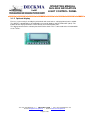
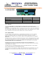
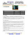
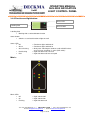
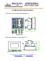
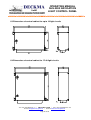
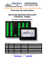
OPERATING MANUAL
NLS-3000 NAVIGATION
LIGHT CONTROL PANEL
Technical documentation
NLS-3000 NAVIGATION LIGHT
CONTROL PANEL
For use on seagoing vessels
Change status
Version Date
0.1
07.08.2008
Author
STO
Checked
HN
Remark
1. Edition
Tel: +49 (0)4105/65 60 – 0 * DECKMA GmbH * Fax: +49 (0)4105/65 60 – 25
E-mail: [email protected] * Internet: www.deckma-gmbh.de
Page 1 of 26
OPERATING MANUAL
NLS-3000 NAVIGATION
LIGHT CONTROL PANEL
Table of contents
1. Application and design
3
2. Modules
4
3.0 Description of modules
3.1 Main module MM01-E
3.2 LM08-E 8-circuit light module
3.3 LM02-E 2-circuit light module
3.4 BK01-E conventional control panel
3.5 Graphic control panel
3.6 VM01-E VDR module
3.7 SM01-E interface module
3.8 DT01-E data module
5-6
7-8
9-10
11-13
14-16
17
18
19
4.0 Operation of NLS-3000 via conventional BK01-E
20-21
5.0 Operation of NLS-3000 via graphic BG01-E
22-23
6.0 Mechanical specification
6.1 BK01-E conventional control panel
6.2 BG01-E graphic control panel
6.3 Control cabinet for up to 16 light circuits
6.4 Control cabinet for 17-48 light circuits
24
24
25
25
7.0 Installation instructions
7.1 Cable requirements
26
8.0 Drawings
27 and following
Tel: +49 (0)4105/65 60 – 0 * DECKMA GmbH * Fax: +49 (0)4105/65 60 – 25
E-mail: [email protected] * Internet: www.deckma-gmbh.de
Page 2 of 26
OPERATING MANUAL
NLS-3000 NAVIGATION
LIGHT CONTROL PANEL
1. Application and design
The NLS3000 navigation light control panel serves for switching and monitoring up to 48 lights
onboard ships. These can be switched on or off individually. Two power supplies can be provided for
the lights (main and backup). Selection between these two supplies can take place either manually or
automatically in the event of failure of the power supply currently in use.
The NLS3000 navigation light control panel is in a modular design. The light modules (light switching
and monitoring) are installed in a control cabinet together with the main module (power and master
module monitoring). The control panels (conventional with buttons and LEDs or graphic with
touchscreen) can be arranged projecting.
The individual modules are interconnected via a bus cable that supplies the modules with operating
voltage.
The system is organised according to the master-slave principle. This means that a master module
collects the information from the slave modules, evaluates and manages the information and initiates
actions at the slave modules.
For this purpose, the master (main module) must know which lights must be evaluated with which
values and what actions need to be initiated in the event of failure. The system topology must also be
known. This is achieved by the configuration of the main module and is permanently stored in the
internal EEPROM. This configuration is simply written into the main module by text file transfer
(terminal or SD card via data module). The text file containing configuration data and menu texts is
arranged so that it can effectively be generated from Microsoft Excel tables.
Tel: +49 (0)4105/65 60 – 0 * DECKMA GmbH * Fax: +49 (0)4105/65 60 – 25
E-mail: [email protected] * Internet: www.deckma-gmbh.de
Page 3 of 26
OPERATING MANUAL
NLS-3000 NAVIGATION
LIGHT CONTROL PANEL
2. Modules
2.1 NLS 3000 MM01-E
•
•
•
•
•
•
•
Main module
Supply 230V/115V AC or 24V DC
Main and backup power switching
Power for modules and distribution for bus system
2 relay outputs for signalling
2 optocoupler inputs for signalling
Optional control panel with LCD display
Data module interface (FMS 3000 DT01-E)
2.2 NLS 3000 LM08-E
•
•
2.3 NLS 3000 LM02-E
•
•
VDR module (identical with FMS 3000)
Connection to VDR
2.7 NLS 3000 SM01-E
•
Graphic control panel (with touchscreen)
Graphic control panel with touchscreen (control options as on conventional control panel)
jpg background images for light positions
2.6 NLS 3000 VM01-E
•
Conventional control panel (mimic)
Ship mimic with 7 LEDs for main lights
Display and switching option for up to 48 individual lights
4x buttons for special light functions
Backlit button labelling field (dimmable)
2.5 NLS 3000 BG01-E
•
•
2-circuit light module
2 monitored, switched and protected light circuits
Main and backup power switching
2.4 NLS 3000 BK**-E
•
•
•
•
8-circuit light module
8 monitored, switched and protected light circuits
Main and backup power switching
Slave module (identical with FMS 3000)
Connect to ship automation system
2.8 NLS 3000 DT01-E
•
•
•
•
Data module (identical with FMS 3000)
Module for data management and editing on SD card
Only for connection to specific interface
Identically used in FMS 3000
Use for service purposes
2.9 FMS 3000 RS232 terminal adapter
•
•
Adapter for connection of data module interface 8 (on NLS 3000 MM01-E) with PC RS232
Use for service purposes (see separate service manual)
Tel: +49 (0)4105/65 60 – 0 * DECKMA GmbH * Fax: +49 (0)4105/65 60 – 25
E-mail: [email protected] * Internet: www.deckma-gmbh.de
Page 4 of 26
OPERATING MANUAL
NLS-3000 NAVIGATION
LIGHT CONTROL PANEL
3. Description of modules
3.1NLS 3000 MM01-E
Main module
Width
Height
Depth
Mounting method
Weight
168 mm
108 mm
50 mm
+ connector about 80mm
Top-hat rail DIN EN 50022
0.5 kg
3.1.1 General
The main module is the communication master within the NLS communication system. In addition to
the power for the connected modules, the main module includes a power monitoring circuit. The main
module also has a connection for an optional DT01-E data module.
The main module has 10 connections for modules supplying a total power of about 4A.
For conversion of the 230V AC and 115V AC power supplies to the 24V DC internal system supply,
an option for the connection of two external power supplies is provided.
3.1.2 Overview of control and indicating elements
NLS 3000 MM01-E main module
Not yet available
Tel: +49 (0)4105/65 60 – 0 * DECKMA GmbH * Fax: +49 (0)4105/65 60 – 25
E-mail: [email protected] * Internet: www.deckma-gmbh.de
Page 5 of 26
OPERATING MANUAL
NLS-3000 NAVIGATION
LIGHT CONTROL PANEL
3.1.2 Optional display
For easy system analysis and display of nominal and actual values, a display board can be added.
The display is controlled by a microcontroller via an 8-bit databus and RS, RW and E (clock). The
buttons on the display board are read-in directly via microcontroller ports.
The display board also has a battery-backed real-time clock. This is connected to the microcontroller
2
via an I C bus.
Tel: +49 (0)4105/65 60 – 0 * DECKMA GmbH * Fax: +49 (0)4105/65 60 – 25
E-mail: [email protected] * Internet: www.deckma-gmbh.de
Page 6 of 26
OPERATING MANUAL
NLS-3000 NAVIGATION
LIGHT CONTROL PANEL
3.2 NLS 3000 LM08-E
8-circuit light module
Width
Height
Depth
Mounting method
Weight
Supply
Power consumption 24V
275 mm
100 mm
50 mm
+ connector about 80mm
Top-hat rail DIN EN 50022
0.8 kg
24V DC
from NLS bus
max. 0.4 A
3.2.1 General
The "8-circuit light module" is a communication slave within the NLS communication system.
It allows the connection of up to 8 lights which can be switched on or off via relays with two-pole fuse
protection.
The current in the individual light circuits is continuously measured. These values are transferred to
the master which evaluates these values from which it derives status information for the control
panels. Should the current fail to reach the required value, an alarm is generated.
3.2.2 Light circuits
The power supplies (main and backup) are supplied jointly for all 8 lights via JN1. For switching
between the two power supplies, one switching relay for two lights respectively is arranged
downstream of this supply circuit. The respective voltage is then distributed between the individual
light circuits.
Each light circuit has a current sensor for two current ranges. The first switching operation takes place
for currents up to about 200 mA via a shunt, the second for currents up to about 4 A via a Hall sensor.
Both switching operations are sensed by a microcontroller with 10-bit analogue circuit and made
available for further processing via the FMS bus.
Each light circuit has two-pole fuse protection. Each light circuit can be switched by the
microcontroller via one relay respectively. For this purpose, the commands from the master arriving
via the FMS bus are evaluated.
The light circuits are each combined in groups of four on the output connectors JL1 and JL2 from
where separate wiring to the respective lights takes place.
Each light circuit can be switched via a toggle switch independent of the microcontroller. This is also
possible in the event of failed or disconnected electronic circuits, thus enabling emergency light
operation.
Tel: +49 (0)4105/65 60 – 0 * DECKMA GmbH * Fax: +49 (0)4105/65 60 – 25
E-mail: [email protected] * Internet: www.deckma-gmbh.de
Page 7 of 26
OPERATING MANUAL
NLS-3000 NAVIGATION
LIGHT CONTROL PANEL
3.2.3 LEDs and DIP switch functions (microcontroller board)
"EXT" ⇒ External communication: (2 LEDs)
•
•
•
•
Communication status with master via NLS bus system
Green flashing
⇒ Communication without faults
Red short
⇒ Individual communication faults
Red
⇒ Communication in constant fault state
"INT" ⇒ Internal communication: (2 LEDs)
•
•
•
•
Communication status with module-internal A/D converter
Green flashing
⇒ Communication without faults
Red short
⇒ Individual communication faults
Red
⇒ Communication in constant fault state
"OK" ⇒ Light status: (8 green LEDs)
•
•
•
Light circuit status without faults
Green
⇒ Light is switched on and values are correct
Green flashing
⇒ Delay after switching on continues until valid A/D values
are present or "overwrite" is active (DIP switch)
"FAULT" ⇒ Light status: (8 red LEDs)
•
•
•
Light circuit status with faults
Red flashing
⇒ Light fault detected, new fault
Red
⇒ Light fault detected, fault accepted
"OFF" ⇒ Fault "overwrite": (yellow LED, 8-circuit DIP switch)
•
•
•
•
Faults in light circuits are not signalled
LED off
⇒ No "overwrite" active on this module
Yellow LED flashing ⇒ Minimum one "overwrite" active on this module
DIP switch "ON"
⇒ Fault in light circuit is not signalled
"ADR" ⇒ NLS address: (4-circuit DIP switch)
•
•
•
Address in NLS system
Address must correspond with configuration data
Each address may only be set 1x within the entire system
Tel: +49 (0)4105/65 60 – 0 * DECKMA GmbH * Fax: +49 (0)4105/65 60 – 25
E-mail: [email protected] * Internet: www.deckma-gmbh.de
Page 8 of 26
OPERATING MANUAL
NLS-3000 NAVIGATION
LIGHT CONTROL PANEL
3.3 NLS 3000 LM02-E
2-circuit light module
Width
Height
Depth
Mounting method
Weight
Supply
Power consumption 24V
124mm
108 mm
50 mm
+ connector About 80mm
Top-hat rail DIN EN 50022
0.8 kg
24V DC
from NLS bus
max. 0.4 A
3.3.1 General
The "2-circuit light module" is a communication slave within the NLS communication system.
It allows the connection of up to two lights which can be switched on or off via relays with two-pole
fuse protection.
The current in the individual light circuits is continuously measured. These values are transferred to
the master which evaluates these values from which it derives status information for the control
panels. Should the current fail to reach the required value, an alarm is generated.
3.3.2 Light circuits
The power supplies (main and backup) are supplied jointly for all two lights via JN1. For switching
between the two power supplies, one switching relay for two lights respectively is arranged
downstream of this supply circuit. The respective voltage is then distributed between the individual
light circuits.
Each light circuit has a current sensor for two current ranges. The first switching operation takes place
for currents up to about 200 mA via a shunt, the second for currents up to about 4 A via a Hall sensor.
Both switching operations are sensed by a microcontroller with 10-bit analogue circuit and made
available for further processing via the FMS bus.
Each light circuit has two-pole fuse protection. Each light circuit can be switched on by the
microcontroller via one relay respectively. For this purpose, the commands from the master arriving
via the FMS bus are evaluated
The light circuits are each combined on the output connector JL1 from where separate wiring to the
respective lights takes place.
Each light circuit can be switched via a toggle switch independent of the microcontroller. This is also
possible in the event of failed or disconnected electronic circuits, thus enabling emergency light
operation.
Tel: +49 (0)4105/65 60 – 0 * DECKMA GmbH * Fax: +49 (0)4105/65 60 – 25
E-mail: [email protected] * Internet: www.deckma-gmbh.de
Page 9 of 26
OPERATING MANUAL
NLS-3000 NAVIGATION
LIGHT CONTROL PANEL
3.3.3 LEDs and DIP switch functions (microcontroller board)
"EXT" ⇒ External communication: (2 LEDs)
•
•
•
•
Communication status with master via NLS bus system
Green flashing
⇒ Communication without faults
Red short
⇒ Individual communication faults
Red
⇒ Communication in constant fault state
"INT" ⇒ Internal communication: (2 LEDs)
•
•
•
•
Communication status with module-internal A/D converter
Green flashing
⇒ Communication without faults
Red short
⇒ Individual communication faults
Rot
⇒ Communication in constant fault state
"OK" ⇒ Light status: (2 green LEDs)
•
•
•
Light circuit status without faults
Green
⇒ Light is switched on and values are correct
Green flashing
⇒ Delay after switching on continues until valid A/D values
are present or "overwrite" is active (DIP switch)
"FAULT" ⇒ Light status: (2 red LEDs)
•
•
•
Light circuit status with faults
Red flashing
⇒ Light fault detected, new fault
Red
⇒ Light fault detected, fault accepted
"OFF" ⇒ Fault "overwrite": (yellow LED, 8-circuit DIP switch – switch 7/8)
•
•
•
•
Faults in light circuits are not signalled
LED off
⇒ No "overwrite" active on this module
Yellow LED flashing ⇒ Minimum one "overwrite" active on this module
DIP switch "ON"
⇒ Fault in light circuit is not signalled
"ADR" ⇒ NLS address: (8-circuit DIP switch – switch 1-5)
•
•
•
Address in NLS system
Address must correspond with configuration data
Each address may only be set 1x within the entire system
Tel: +49 (0)4105/65 60 – 0 * DECKMA GmbH * Fax: +49 (0)4105/65 60 – 25
E-mail: [email protected] * Internet: www.deckma-gmbh.de
Page 10 of 26
OPERATING MANUAL
NLS-3000 NAVIGATION
LIGHT CONTROL PANEL
3.4 NLS 3000 BK01-E
Width
Height
Depth
Mounting method
Weight
Conventional control panel (mimic)
111.5 mm
144
mm
176.5 mm
209
mm
241,5 mm
274
mm
144
mm
60
mm
+ connector
Front panel mounting
0,6 kg
NLS 8
NLS 16
NLS 24
NLS 32
NLS 40
NLS 48
About 130 mm
NLC 16
3.4.1 General
The "conventional control panel" is a communication slave within the NLS communication system.
It serves for display and control of the NLS, enabling lights to be switched on or off. From this control
panel, the NLS generates visual and audible alarms on faults in the light circuits or in the NLS and
system power supply.
3.4.2 Buttons
Each individual button consists of a button, a status LED arranged above and a labelling field located
on the left. The labelling field (dimmable) is backlit. Marking of the labelling fields takes place via an
insertable strip that can be adapted for various projects.
3.4.3 General buttons
For general control of the NLS, permanent and configurable functions are implemented. The
associated buttons are arranged in the left section of the control panel or directly below the ship
mimic.
Tel: +49 (0)4105/65 60 – 0 * DECKMA GmbH * Fax: +49 (0)4105/65 60 – 25
E-mail: [email protected] * Internet: www.deckma-gmbh.de
Page 11 of 26
OPERATING MANUAL
NLS-3000 NAVIGATION
LIGHT CONTROL PANEL
3.4.5 Power und System:
Emergency LED
System status LED
Main LED
Power status LED
Labelling field
Power status button
Labelling field
• Marking with button function: Here "Power"
Power status button
• Switches the power for the lights
• Pressing this button switches on the power via "MAIN"
• With the power switched on, switching takes place between "MAIN" and "EMGY"
• Pressing and holding this button switches off the power after about 3 seconds
Power status LED
• Off
• Green
• Red flashing
• Red
⇒ Power off
⇒ Power on
⇒ No power ("MAIN" or "EMGY"), new fault
⇒ No power ("MAIN" or "EMGY"), fault accepted
System status LED
• Green
• Red flashing
⇒ System without faults
⇒ System fault (e.g. module not accessible)
Main LED and Emergency LED
a. "Power off" status
• Green
• Green flashing
b. In "Power on" status
• Green
• Off
• Green flashing
⇒ Power available
⇒ No power
⇒ Lights currently supplied via this power supply
⇒ Lights not currently supplied via this power supply
⇒ No power
Tel: +49 (0)4105/65 60 – 0 * DECKMA GmbH * Fax: +49 (0)4105/65 60 – 25
E-mail: [email protected] * Internet: www.deckma-gmbh.de
Page 12 of 26
OPERATING MANUAL
NLS-3000 NAVIGATION
LIGHT CONTROL PANEL
3.4.6 Function and light button:
Status LED
Labelling field
Status button
Labelling field
• Marking with associated button function
Status button
• Switches associated function or light on or off
Status LED
• Off
• Green
• Green flashing
•
•
Red flashing
Red
⇒ Function or light switched off
⇒ Function or light switched on
⇒ Delay after switching on continues until valid A/D values
are present or "overwrite" is active (DIP switch)
⇒ Light fault detected, new fault
⇒ Light fault detected, fault accepted
Mimic:
Mimic LEDs
• Off
• On
• Flashing
⇒ Light switched off
⇒ Light switched on
⇒ Light fault detected
Tel: +49 (0)4105/65 60 – 0 * DECKMA GmbH * Fax: +49 (0)4105/65 60 – 25
E-mail: [email protected] * Internet: www.deckma-gmbh.de
Page 13 of 26
OPERATING MANUAL
NLS-3000 NAVIGATION
LIGHT CONTROL PANEL
3.5 NLS 3000 BG01-E
Graphic control panel
(with touchscreen)
Width
Height
Depth
Mounting method
Weight
Connection NLS Bus In
Connection NLS Bus Out
Supply
Power consumption 24V
Display visible area
Display resolution
Display colours
120
mm
95
mm
60
mm
+connector
Front panel mounting
0.4 kg
15-pin Dsub male
15-pin DSub female
24V DC
max. 0.3 A
95.4 mm x 53.9 mm
480 x 272 pixels
16 it (65,536)
About 130 mm
JP1
JPT1
from NLS bus
3.5.1 General
The "graphic control panel" is a communication slave within the NLS communication system.
It serves for display and control of the NLS, enabling lights to be switched on or off. From this control
panel, the NLS generates visual and audible alarms on faults in the light circuits or in the NLS and
system power supply.
Tel: +49 (0)4105/65 60 – 0 * DECKMA GmbH * Fax: +49 (0)4105/65 60 – 25
E-mail: [email protected] * Internet: www.deckma-gmbh.de
Page 14 of 26
OPERATING MANUAL
NLS-3000 NAVIGATION
LIGHT CONTROL PANEL
3.5.2 Power und System:
Power status LED
Main LED
Power status button
Emergency LED
System status LED
Labelling field
• Marking with button function: Here "Power"
Power status button
• Switches the power for the lights
• Pressing this button switches on the power via "MAIN"
• With the power switched on, switching takes place between "MAIN" and "EMGY"
• Pressing and holding this button switches off the power after about 3 seconds
Power status LED
• Off
• Green
• Red flashing
• Red
⇒ Power off
⇒ Power on
⇒ No power ("MAIN" or "EMGY"), new fault
⇒ No power ("MAIN" or "EMGY"), fault accepted
System status LED
• Green
• Red flashing
⇒ System without fault
⇒ System fault (e.g. module not accessible)
Main LED and Emergency LED
a. In "Power off" status
• Green
• Green flashing
b. In "Power on" status
• Green
• Off
• Green flashing
⇒ Power available
⇒ No power
⇒ Lights currently supplied via this power supply
⇒ Lights not currently supplied via this power supply
⇒ No power
Tel: +49 (0)4105/65 60 – 0 * DECKMA GmbH * Fax: +49 (0)4105/65 60 – 25
E-mail: [email protected] * Internet: www.deckma-gmbh.de
Page 15 of 26
OPERATING MANUAL
NLS-3000 NAVIGATION
LIGHT CONTROL PANEL
3.5.3 Function and light button:
Status LED
Status button
Labelling field
Labelling field
• Marking with associated button function
Button status
• Switches associated function or light on or off
Status LED
• Off
• Green
• Green flashing
•
•
Red flashing
Red
⇒ Function or light switched off
⇒ Function or light switched on
⇒ Delay after switching on continues until valid A/D values
are present or "overwrite" is active (DIP switch)
⇒ Light fault detected, new fault
⇒ Light fault detected, fault accepted
Mimic:
Mimic LEDs
• Off
• On
• Flashing
⇒ Light off
⇒ Light on
⇒ Light fault detected
Tel: +49 (0)4105/65 60 – 0 * DECKMA GmbH * Fax: +49 (0)4105/65 60 – 25
E-mail: [email protected] * Internet: www.deckma-gmbh.de
Page 16 of 26
OPERATING MANUAL
NLS-3000 NAVIGATION
LIGHT CONTROL PANEL
3.6 NLS 3000 VM01-E
VDR module
Width
Height
Depth
Mounting method
Weight
72 mm
104 mm
88 mm
Top-hat rail DIN EN 50022
0.3 kg
3.6.1 General
The VDR module sends data via RS485 or RS232 to a VDR (Voyage Data Recorder). The module
can alternatively be provided with drivers for RS485 or RS232.
The communication profile of the VDR interface depends on the following specifications:
IEC 61162-1
Part 1 Single talker and multiple listeners
IEC 61162-100
Extra requirements for the UAIS
IEC 61162-102
Extra requirements for the Voyage Data Recorder
3.6.2 VDR interface
The microcontroller, an ATmega162 with two serial interfaces, communicates with the master via one
of the interfaces and with the other via the alternative driver provided for RS485 or RS232.
3.6.3 RS485 communication
Communication takes place via an RS485 driver module. The microcontroller takes over direct
communication with the RS485 bus and filters the messages for the VDR module. The two status
LEDs on the module indicate the status of the RS485 interface:
Green LED: Module status scanned by master
Red LED: Communication problem or timeout
Tel: +49 (0)4105/65 60 – 0 * DECKMA GmbH * Fax: +49 (0)4105/65 60 – 25
E-mail: [email protected] * Internet: www.deckma-gmbh.de
Page 17 of 26
OPERATING MANUAL
NLS-3000 NAVIGATION
LIGHT CONTROL PANEL
3.7 NLS 3000 SM01-E
Interface module
Width
Height
Depth
Mounting method
Weight
54 mm
60 mm
17 mm
Plug-in
0.05 kg
Data and power connection
25-pin DSub male
Supply
Power consumption from 5V supply
5V DC
max. 0.005 A
Supplied from module
3.7.1 General
The slave module serves for connection of the NLS 3000 main module to the ship automation system.
It decouples both systems.
3.7.2 Connector
Communication takes place via an RS232 driver module with the main module and via an RS485
module with the ship automation system. The interface output to the ship automation system is
isolated via a digital isolator.
The terminating resistor for the RS485 bus can be connected via a slide switch.
Tel: +49 (0)4105/65 60 – 0 * DECKMA GmbH * Fax: +49 (0)4105/65 60 – 25
E-mail: [email protected] * Internet: www.deckma-gmbh.de
Page 18 of 26
OPERATING MANUAL
NLS-3000 NAVIGATION
LIGHT CONTROL PANEL
3.8 FMS 3000 DT01-E
Data module
Width
Height
Depth
Mounting method
Weight
Data and power connection
Supply
Power consumption
SD card
54 mm
60 mm
17 mm
Plug-in
0.05 kg
25-pin DSub male
5V DC
max. 0.15 A
64MB...1GB
256MB Kingston
recommended
3.8.1 General
The data module serves for the storage of configuration data and data occurring in the operation of
AFMS3000 on an SD memory card. For this purpose, the module contains its own microcontroller,
which makes reading and writing of the SD memory card independent of the higher-level system.
Integration into the system takes place via a special interface.
3.8.2 Power supply
The module receives its 5V power for supplying the microcontroller via the interface. From this
voltage, 3.3V is generated internally for supplying the SD memory card.
3.8.3 Connector
Communication takes place via an RS232 driver module. The data module is also supplied with 5V
operating voltage via the connector.
3.8.4 LEDs
Three status LEDs are provided on the back of the module:
Green LED: Module ok, access to SD card file system possible
Yellow LED: File open for reading or writing
Red LED: Read or write operation, fault on steady light indication
3.8.5 SD memory card slot
A slot is provided at the rear of the module for receiving an SD memory card. This locks in place after
it is pushed into the slot. The memory card can be removed by exerting light pressure on the same.
Tel: +49 (0)4105/65 60 – 0 * DECKMA GmbH * Fax: +49 (0)4105/65 60 – 25
E-mail: [email protected] * Internet: www.deckma-gmbh.de
Page 19 of 26
OPERATING MANUAL
NLS-3000 NAVIGATION
LIGHT CONTROL PANEL
4. 0 Operation of NLS-3000
via conventional BK-01E
4.1 Switching on NLS and power supply switching
Provided for switching the NLS on and off are control and indicating elements arranged directly below
the ship mimic. Two green LEDs (labelled "MAIN" and "EMGY") indicate via a steady light the
presence of the respective power supply. When the NLS is switched on, the LED for the currently
used power supply lights up.
Arranged directly on the right next to the "Power" button is a two-colour LED. When this LED lights
green, both power supplies are present and the NLS is on. In the event of failure of one of the power
supplies, this LED flashes red or shows a steady light.
The NLS is switched on by pressing the "Power" button. The NLS can be switched off by pressing
and holding the button for about 3 seconds. When the button is pressed during operation, switching
takes place between the main and backup power supply.
The "SYS" LED lights green to signal that the NLS is operating without fault and lights red on faults.
4.2 LED brightness setting
There are eight brightness levels for the individual LEDs and button backlight. Provided for this
purpose is the "Back Light" button. The brightness is increased one level each time this button is
pressed. Selection takes place from the highest level to the lowest level. When the button is pressed
and held, these levels are selected in a 0.5 second cycle.
4.3 Lamp test
To test the function of the individual LEDs, a lamp test can be performed. The "Test" button is
provided for this purpose.
4.4 Alarm acceptance
For the acceptance of alarms and simultaneously switching off the buzzer, the "Sound Off" button is
provided.
4.5 Configurable functions
In order to simplify the setting of specific light scenarios, these can be defined via configuration.
Selection can subsequently be made via the buttons labelled according to their specific function.
Tel: +49 (0)4105/65 60 – 0 * DECKMA GmbH * Fax: +49 (0)4105/65 60 – 25
E-mail: [email protected] * Internet: www.deckma-gmbh.de
Page 20 of 26
OPERATING MANUAL
NLS-3000 NAVIGATION
LIGHT CONTROL PANEL
4.6 Light buttons
Each light is assigned a button in the NLS and can be switched on or off via this button. A two-colour
LED is arranged directly on the right next to the button. When the button lights green, the associated
light is on and the power is in the given range. The LED flashes red on faults in the light circuit. After
acceptance of the fault, the LED shows a steady red light.
For lights using LEDs, the operating time is also monitored. If the maximum permissible operating
time is exceeded, a fault is generated.
4.7 Ship mimic
For the main lights, display is provided in the form a ship mimic. When these lights are switched on,
the associated LED in the ship mimic also lights up and flashes on faults.
4.8 Buzzer
The buzzer is controlled via a driver transistor and a microcontroller port circuit. The buzzer is located
on the back of the control panel. It is activated pulsed on faults.
Tel: +49 (0)4105/65 60 – 0 * DECKMA GmbH * Fax: +49 (0)4105/65 60 – 25
E-mail: [email protected] * Internet: www.deckma-gmbh.de
Page 21 of 26
OPERATING MANUAL
NLS-3000 NAVIGATION
LIGHT CONTROL PANEL
5. 0 Operation of NLS-3000
via graphic BG-01E
5.1 Switching on NLS and power supply switching
Provided for switching the NLS on and off are control and indicating elements arranged on the bottom
left of the screen. Two green LEDs (labelled "MAIN" and "EMGY") indicate via a steady light the
presence of the respective power supply. When the NLS is switched on, the LED for the currently
used power supply lights up.
Arranged directly next to the "Power" button is a two-colour LED. When this LED lights green, both
power supplies are present and the NLS is on. In the event of failure of one of the power supplies, this
LED flashes red or shows a steady light.
The NLS is switched on by pressing the "Power" button. The NLS can be switched off by pressing
and holding the button for about 3 seconds. When the button is pressed during operation, switching
takes place between the main and backup power supply.
The "SYS" LED lights green to signal that the NLS is operating without fault and lights red on faults.
5.2 Backlight brightness setting
The display backlight has ten brightness settings. Provided for this purpose is the "Back Light" button.
The brightness is increased one level each time this button is pressed. Selection takes place from the
highest level to the lowest level. It is also possible to invert the display by pressing the "Invert Display"
button.
5.3 Alarm acceptance
For the acceptance of alarms and simultaneously switching off the buzzer, the "Sound Off" button is
provided. This is only displayed when the buzzer is active.
5.4 Configurable functions
In order to simplify the setting of specific light scenarios, these can be defined via configuration.
Selection can subsequently be made via the buttons labelled according to their specific function.
5.5 Light buttons
Each light is assigned a button in the NLS and can be switched on or off via this button. A two-colour
LED is arranged directly on the right next to the button. When the button lights green, the associated
light is on and the power is in the given range. The LED flashes red on faults in the light circuit. After
acceptance of the fault, the LED shows a steady red light.
For lights using LEDs, the operating time is also monitored. If the maximum permissible operating
time is exceeded, a fault is generated.
Tel: +49 (0)4105/65 60 – 0 * DECKMA GmbH * Fax: +49 (0)4105/65 60 – 25
E-mail: [email protected] * Internet: www.deckma-gmbh.de
Page 22 of 26
OPERATING MANUAL
NLS-3000 NAVIGATION
LIGHT CONTROL PANEL
5.6 Ship mimic
For the main lights, display is provided in the form a ship mimic. When these lights are switched on,
the associated LED in the ship mimic also lights up and flashes on faults.
5.7 Buzzer
The buzzer is controlled via a driver transistor and a microcontroller port circuit. The buzzer is located
on the back of the control panel. It is activated pulsed on faults.
Tel: +49 (0)4105/65 60 – 0 * DECKMA GmbH * Fax: +49 (0)4105/65 60 – 25
E-mail: [email protected] * Internet: www.deckma-gmbh.de
Page 23 of 26
OPERATING MANUAL
NLS-3000 NAVIGATION
LIGHT CONTROL PANEL
6.0 Mechanical specifications
6.1 Dimensions of conventional control panel BK 01- E
6.2 Dimensions of graphic control panel BG 01- E
Tel: +49 (0)4105/65 60 – 0 * DECKMA GmbH * Fax: +49 (0)4105/65 60 – 25
E-mail: [email protected] * Internet: www.deckma-gmbh.de
Page 24 of 26
OPERATING MANUAL
NLS-3000 NAVIGATION
LIGHT CONTROL PANEL
6.3 Dimensions of control cabinet for up to 16 light circuits
6.4 Dimensions of control cabinet for 17-48 light circuits
Tel: +49 (0)4105/65 60 – 0 * DECKMA GmbH * Fax: +49 (0)4105/65 60 – 25
E-mail: [email protected] * Internet: www.deckma-gmbh.de
Page 25 of 26
OPERATING MANUAL
NLS-3000 NAVIGATION
LIGHT CONTROL PANEL
7.0 Installation instructions
7.1 Cable requirements
The following cables are recommended for safe and reliable operation of the complete system
Main and emergency power supply
Light outputs
Output contacts
Control inputs
VDR output
Control panel
Max. length 500 m
unshielded cable min.
unshielded cable min.
unshielded cable min.
shielded cable min.
shielded twisted pair
shielded twisted pair
3x1.5mm ²
3x1.5mm ²
2x0.75mm ²
2x0.75mm ²
2x2x0.75mm ²
2x2x0.75mm ²
Tel: +49 (0)4105/65 60 – 0 * DECKMA GmbH * Fax: +49 (0)4105/65 60 – 25
E-mail: [email protected] * Internet: www.deckma-gmbh.de
Page 26 of 26