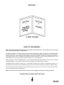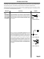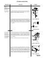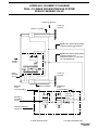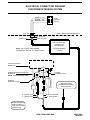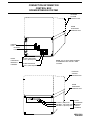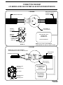
1
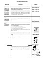
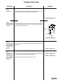
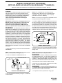
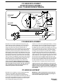
HW H
R
CORPORATION
SERVICE MANUAL
FOR WINNEBAGO MOTORIZED VEHICLES
610 SERIES HYDRAULIC LEVELING SYSTEM
SPACEMAKER ROOM EXTENSION SYSTEM
R
FEATURING:
Dual Cylinder "Rail" Room Extension (With Rack Sensing Valve)
HWH CORPORATION
(On I-80, Exit 267 South)
2096 Moscow Road | Moscow, Iowa 52760
Ph: 800/321-3494 (or) 563/724-3396 | Fax: 563/724-3408
www.hwh.com
ML11759/MI91.0008
05MAY04
SECTION 1
N
TIO
SEC
1
E
UBL
O
R
T
TING
O
O
SH IDE
GU
SEC
TION
2
FIGU
RES
2 PART FOLDER
HOW TO USE MANUAL
NOTE: This manual will work for systems with single cylinder room extensions also. The only difference is the exclusion
of rack sensing valve problems or adjustments.
This manual is written in two sections. Section 1 is the Trouble Shooting Guide. Section 2 is the figures. Begin diagnosis of
the system with Section 1, the Trouble Shooting Guide. The Trouble Shooting Guide is broken into 3 columns, Problem,
Solutions and Figures. Under Problems, find the symptom you have encountered. The testing and repair for that problem is
in the Solution (center) column. Diagrams for a particular Problem and Solution are in the Figures (right hand) column. This
column will direct you to the proper figure in Section 2, Figures, for a more detailed view.
Before beginning your repair, it is IMPORTANT to read the CAUTIONS and NOTES AND CHECKS in the first section, TROUBLE
SHOOTING GUIDE. In many cases this will save time and mistakes when trouble shooting a system.
This Repair Manual is offered as a guide only. It is impossible to anticipate every problem or combination of problems. For
any problems encountered that are not addressed in this manual, contact HWH Corporation for assistance. (800-321-3494)
The room should be fully retracted before Trouble Shooting the system. If the room will not retract, use the manual retract procedure on pages MP35.9410 and MP35.9490.
Make sure all room locks and the manual retract winch are not engaged before trouble shooting the system.
PROCEED WITH TROUBLE SHOOTING GUIDE
MI91.1005
05AUG96
TROUBLE SHOOTING
WARNING!
BLOCK FRAME AND TIRES SECURELY BEFORE CRAWLING UNDER VEHICLE. DO NOT USE THE LEVELING
JACKS OR AIR SUSPENSION TO SUPPORT VEHICLE WHILE UNDER VEHICLE OR CHANGING TIRES. VEHICLE
MAY DROP AND OR MOVE FORWARD OR BACKWARD WITHOUT WARNING CAUSING INJURY OR DEATH.
WHEN ROUTING OR REROUTING HYDRAULIC HOSES AND WIRES, BE SURE THEY ARE NOT EXPOSED TO ENGINE
EXHAUST OR ANY HIGH TEMPERATURE COMPONENTS OF THE VEHICLE.
NEVER PLACE HAND OR OTHER PARTS OF THE BODY NEAR HYDRAULIC LEAKS. OIL MAY CUT AND
PENETRATE THE SKIN CAUSING INJURY OR DEATH.
SAFETY GLASSES ARE TO BE WORN TO PROTECT EYES FROM DIRT, METAL CHIPS, OIL LEAKS, ETC. FOLLOW
ALL OTHER SHOP SAFETY PRACTICES.
NOTES AND CHECKS
Read and check before proceeding with Trouble Shooting Steps.
NOTE: HWH CORPORATION ASSUMES NO LIABILITY
FOR DAMAGES OR INJURIES RESULTING FROM THE
INSTALLATION OR REPAIR OF THIS PRODUCT.
1. The leveling system must work correctly or the room extension will not function properly. If the leveling system is not
working correctly, refer to the HWH 610 Series Repair Manual
Number ML1681.
2. The following conditions must be met for the room extension to operate. The ignition must be in the "ACC" position
and the park brake must be set. The HWH leveling system
panel must be on. A red Jacks Down Warning Light on the
HWH Panel must be on.
3. If the room extension cannot be retracted, see Figures
page MP35.9490 for temporary measures. Make sure the
manual retract valves are closed before trouble shooting.
If the room will not retract using the manual winch, there may
be a problem with the rack sensing valve. DO NOT use alternate devices such as a power winch to retract the room. See
Part 9 of the Trouble Shooting Section.
IMPORTANT : The room extension will not operate unless a
jack is extended enough to turn a Jacks Down Warning light on,
but the vehicle should NOT be supported by the leveling jacks
when working on the room extension.
4. Check that the oil reservoir is full with the room and the leveling system in the fully retracted position.
5. Batteries should read 12.6 volts. Batteries must be in good
condition with no weak cells. An alternator, converter or battery
charger will not supply enough power for the system to operate
properly.
6. Proper ground of all components is critical. See the electrical circuit for specific grounds required. Faulty grounds,
especially for the solenoid manifold or the pump assembly,
may cause component damage and /or improper or erratic
operation.
This manual is intended for use by experienced mechanics
with knowledge of hydraulic and automotive electrical
systems. People with little or no experience with HWH
Room Extension systems should contact HWH technical
service (800-321-3494) before beginning. Special attention
should be given to all cautions, wiring, and hydraulic diagrams.
Tightening of hose ends: If tightening a new hose end,
make the hose end snug (finger tight) on the fitting, then
tighten the hose end 1/3 turn (2 FLATS). If tightening an
existing hose end, tighten the hose end to snug plus 1/4
turn (1 FLAT).
Suggested tools for trouble shooting the HWH room extension
systems:
JUMPER WIRES (UP TO 10 GAUGE)
PRESSURE GAUGE (3500 PSI MIN.)
MULTI-METER
12 VOLT TEST LIGHT
PROCEED WITH THE TROUBLE
SHOOTING STEPS ON THE
FOLLOWING PAGE
MI91.1043
25APR11
TROUBLE SHOOTING
The following is a list of possible problems and solutions which might occur to room extensions. Only qualified technicians
should install or repair room extension systems. An understanding of the operation of the room extension hydraulic and electrical components is required. Contact HWH Corporation technical service for assistance at (800-321-3494).
The following conditions must be met for the room extension to operate. The ignition must be in the "ACC" position. The park
brake must be set. The HWH leveling system panel must be on. A red "Jack Down Warning Light" on the HWH panel must be
on. (A jack must be extended approximately two inches.)
PROBLEM
SOLUTION
Part 1
The pump will
not run when the
room extension
switch is pushed
toward EXTEND
and/or RETRACT.
Check the POWER pin on the control box. If power is not present,
replace the control box. If power is present, check the EXTEND and
RETRACT pins while pushing the room control switch. Do not disconnect the harness. If power is present on the EXTEND and RETRACT pin pushing the switch to EXTEND and RETRACT, replace
the control box.
FIGURES
RED - POWER
YELLOW - EXTEND
BLACK - RETRACT
REFER TO MP85.5210
Power is not present at the EXTEND and RETRACT pins on the
control box while pushing the room control switch. Check for
power on Terminal 2 of the room control switch. If power is not present, check the WINNEBAGO wire marked GC of the 6-pin UML connection, or the red wire in the HWH room extension control harness.
RETRACT - DU
POWER - GC
8
1
EXTEND - DR
2
3
7
4
5
ROOM
CONTROL
SWITCH
6
6-PIN UML
6-PIN UML
REFER TO MP85.5090
If power is present on Terminal 2, check Terminals 1 and 3 while pushing the control switch to RETRACT and EXTEND. If power is not present, replace the switch. If power is present on Terminals 1 and 3,
check the WINNEBAGO wire marked DU on the 6-pin UML connection or the HWH black wire for RETRACT or the WINNEBAGO wire
marked DR on the 6 pin UML connection or the HWH yellow wire for
for EXTEND.
YELLOW
EXTEND
BLACK
RETRACT
RED
+12 VOLT
FROM CONTROL BOX
REFER TO MP85.5230
MI91.2070
12MAY97
TROUBLE SHOOTING
PROBLEM
SOLUTION
FIGURES
Part 2
The pump runs
but the room will
not extend.
a. The pump runs
under no load.
The retract valve is open. Make sure the solenoid valve "T" handle is
closed. Check for +12 power on the black wire at the manifold. If
power is not present, replace the retract valve.
RETRACT
SOLENOID
VALVE
AB
(A) WHITE
(B) BLACK
REFER TO MP85.5090
If there is power on the black wire, unplug the wire marked "DU" from
the control switch. Check Terminal 1 on the room control switch, while
pushing the switch toward the "EXTEND" position. If there is power replace the switch. If there is no power, on Terminal 1 the WINNEBAGO
wire marked "DU" or the black wire in the HWH harness is shorted to a
+12 supply.
RETRACT - DU
POWER - GC
EXTEND - DR
8
1
2
3
7
4
5
6
ROOM
CONTROL
SWITCH
6-PIN UML
6-PIN UML
BLACK
REFER TO MP85.5090
The extend solenoid valve is not opening. While pushing the room
control switch toward "EXTEND", check between the yellow and white
wire of the extend valve plug for +12 power. If power is present, replace the extend solenoid valve. If power is not present, check between the yellow wire and ground. If power is present, repair the white
wire in the plug.
EXTEND
SOLENOID
VALVE
NOTE : Low voltage may cause a solenoid valve not to open.
AB
YELLOW (B)
WHITE (A)
REFER TO MP85.5090
Power is not present on the yellow and white wire of the extend
valve plug. Check the "EXTEND" fuse at the control box. If the fuse
is blown, check the harness. Then replace the extend solenoid valve
if the harness is OK. If the fuse is OK, check the EXTEND pin in the
9-pin UML on the control box while pushing the switch toward "EXTEND". If the power is present, the problem is with the harness. If
power is not present on the "EXTEND" pin, replace the control box.
10 AMP
EXTEND
FUSE
10AMP
b. The pump runs
under a load.
If the pump is running, the room operator’s panel and
the room extension
control switch harness is OK.
EXTEND SOLENOID
VALVE - YELLOW
REFER TO MP85.5210
MI91.2073
12MAY97
TROUBLE SHOOTING
PROBLEM
SOLUTION
FIGURES
Part 3
The pump runs
but the room will
not retract.
a. The pump runs
under no load.
EXTEND
SOLENOID
VALVE
The extend valve is open. Make sure the solenoid valve "T" handle is
closed. Check for +12 power on the yellow wire at the manifold. If
power is not present, replace the extend valve.
AB
YELLOW (B)
WHITE (A)
If there is power on the yellow wire, unplug the wire marked "DR" from
the control switch. Check Terminal 3 on the room control switch, while
pushing the switch toward the "RETRACT" position. If there is power,
replace the switch. If there is no power on Terminal 3 the WINNEBAGO
wire marked "DR" or the yellow wire in the HWH harness is shorted to
a +12 supply.
REFER TO MP85.5090
RETRACT - DU
POWER - GC
EXTEND - DR
8
1
2
3
7
4
5
6
ROOM
CONTROL
SWITCH
6-PIN UML
6-PIN UML
REFER TO MP85.5090
The retract solenoid valve is not opening. While pushing the room
control switch toward "RETRACT", check between the black and white
wire of the retract valve plug for +12 power. If power is present, replace the extend solenoid valve. If power is not present, check between the black wire and ground. If power is present, repair the white
wire in the plug.
RETRACT
SOLENOID
VALVE
NOTE : Low voltage may cause a solenoid valve not to open.
AB
(A) WHITE
(B) BLACK
REFER TO MP85.5090
Power is not present on the black and white wire of the retract
valve plug. Check the "RETRACT" fuse at the control box. If the fuse
is blown, check the harness. Then replace the extend solenoid valve
if the harness is OK. If the fuse is OK, check the RETRACT pin in the
9-pin UML on the control box while pushing the switch toward "RETRACT". If the power is present, the problem is with the harness. If
power is not present on the "RETRACT" pin, replace the control box.
RETRACT
FUSE
10AMP
b. The pump runs
under a load.
If the pump is running, the room operator’s panel and
the room extension
control switch harness is OK.
RETRACT SOLENOID
VALVE - BLACK
REFER TO MP85.5210
MI91.2076
12MAY97
TROUBLE SHOOTING
PROBLEM
SOLUTION
FIGURES
Part 4
The room moves
erratically from
side to side (walking) as it extends
or retracts (dual
cylinder room extensions only).
Important: An adjustment will not
fix this problem.
Check that the pivot bracket is free to pivot. Check that the inner tubes
are free of paint or undercoating. Check that the left cylinder hydraulic
lines are not wire tied to the room closer than 12 inches to the rack sensing valve support arm. (SEE MP45.9415)
REFER TO MP45.9415
Check that the strike plate is mounted solidly to the room, and that the
rack sensing valve plunger is properly positioned on the strike plate.
Check that the plunger is not bent. (SEE MP35.9410) Check that the
room itself is not binding on seals or other interferences. Then replace
the rack sensing valve. (SEE MP45.9420)
REFER TO MP45.9420
Part 5
The ends of the
room do not move
at an equal distance from the vehicle.
Part 6
The room creeps
out after being retracted.
REFER TO MP35.9410
The rack sensing valve needs to be adjusted. See MP45.9420 for valve
adjustment procedures.
REFER TO MP45.9420
The following deals with either single or dual cylinder room extensions.
There are three possibilities :
A : An extend solenoid valve is leaking.
B : A room extension cylinder has an internal leak.
C : The manifold check valve is leaking.
CAP END
ROD END
HYDRAULIC CYLINDER
Note : If the room creeps out 1 inch more or less the problem is most
likely the check valve.
HYDRAULIC CYLINDER
CAP END
ROD END
ROOM EXTENSION
Retract the room completely. Remove the hydraulic line for the cap
end of the cylinder at the manifold. Hold the hose end in an upright
position. Press the rocker switch for that room to the "RETRACT"
position.
REFER TO MP65.055
If fluid flows from the manifold fitting, the extend solenoid valve needs
to be changed.
1E
EXTEND
SOLENOID
VALVE (1E)
1R
BA
BA
YELLOW
WHITE
REFER TO MP85.5090
MANIFOLD
CHECK
VALVE
If no fluid flows from either the hose end or the manifold fittings, inspect the manifold check valve. There is a spring below the cap. DO
NOT lose the spring. Check for cuts on the poppet "O" ring. Check
the poppet and cap for burrs. The poppet should easily slide in the
cap.
1E
EXTEND
SOLENOID
VALVE (1E)
1R
BA
MANIFOLD
CHECK
VALVE
BA
CAP
SPRING
POPPET
O-RING
DETAIL A
REFER TO MP85.5090
MI91.2079
03APR97
TROUBLE SHOOTING
PROBLEM
Part 6
Continued
SOLUTION
FIGURES
If the check valve is OK, or fluid flows from the hose end, the room
extension cylinder should be replaced. See MP45.9415
REFER TO MP45.9415
Part 7
The room creeps
back in after being
extended.
Check for visible oil leaks. If there are none, replace the retract
solenoid valve for that room extension. This is the only possibility
that would cause this problem.
RETRACT
SOLENOID
VALVE
AB
(A) WHITE
(B) BLACK
REFER TO MP85.5090
Part 8
The room does
not seal tightly
when fully retracted or extended.
The room stops need to be adjusted. See the adjustment section of
MP45.9415
REFER TO MP45.9415
Part 9
One side of the
room will not
move while trying to extend
and/or retract
the room.
The rack sensing valve is not working properly. Refer to MP45.9420
for rack sensing valve replacement and adjustment.
REFER TO MP45.9420
REFER TO MP35.9410
Refer to MP35.9410 for temporary retract procedure.
MI91.2082
24MAY96
MANUAL ROOM RETRACT PROCEDURE
USE ONLY WHEN ROOM CANNOT BE RETRACTED WITH THE ROOM CONTROL
SWITCH OR THE MANUAL RETRACT WINCH.
THIS SHOULD BE DONE BY A CERTIFIED TECHNICIAN ONLY.
CONTACT HWH CORPORATION FOR ASSISTANCE AT (1-800-321-3494).
When extending or retracting the room, if one side of the room does not move, release the room control switch immediately.
The rack sensing valve plunger (1, FIGURE 1) may be stuck, bent or not touching the strike plate (2, FIGURE 1).
REAR ROOM
EXTENSION TUBES
3
1
4
5
2
FRONT ROOM
EXTENSION TUBES
FIGURE 1
ROOM IN EXTENDED POSITION
Refer to page MP35.9490 in the Operator’s Manual or the repair manual, and try to manually retract the room, if it is extended.
If the manual winch provided will not retract the room, DO NOT USE ALTERNATE DEVICES SUCH AS A POWER
WINCH. If possible repair the rack sensing valve (3, FIGURE 1) before retracting the room. If repair is not possible, release the
pressure on the manual retract winch. Remove the check valve cap (4, FIGURE 1) from the back of the rack sensing valve. Remove the check valve poppet (5, FIGURE 1). Replace the check valve cap. Retract the room using the manual retract winch according to MP35.9490. DO NOT use the room extension until the rack sensing valve has been replaced. Leave
the manual winch in place and have the room extension repaired.
WARNING:
ROOM EXTENSION SOLENOID VALVE "T" HANDLES MUST BE IN THE OPEN POSITION WHEN THE
MANUAL RETRACT WINCH IS CONNECTED. DO NOT USE THE ROOM EXTENSION OR LEVELING SYSTEM WHEN THE
ROOM EXTENSION HYDRAULIC HOSES ARE DISCONNECTED.
2
1
3
4
FIGURE 2
ROOM IN RETRACTED POSITION
If one side of the room will not move while extending, repair the rack sensing valve before continuing. Remove the cylinder adjusting locknut (1, FIGURE 2). Turn the cylinder adjusting rod (2, FIGURE 2) clockwise as far as possible. If this is not enough
room to work on the valve, remove the cylinder mounting plate nuts (3, FIGURE 2) and the cylinder mounting plate (4, FIGURE
2). The room can then be pulled out far enough to work on the rack sensing valve. Contact HWH Corporation, 1-800-321-3494,
for the correct rack sensing valve and cylinder replacement and adjustment instruction sheets.
MP35.9410
02FEB12
MANUAL ROOM RETRACT PROCEDURE
(WITH SOLENOID VALVES WITH VALVE RELEASE "T" HANDLES)
(USE ONLY WHEN THE ROOM WILL NOT RETRACT WITH THE ROOM CONTROL SWITCH)
OVERVIEW
The room can be retracted manually if a hydraulic or electric
failure prevents the room from being retracted using the
CONTROL SWITCH. For normal retract sequence see the
ROOM SLIDE RETRACT PROCEDURES. Refer to the
vehicle manufacturer for storage location of the
retract device and information for connecting the
device to the room.
IMPORTANT: If the vehicle is not equipped with a winch,
DO NOT use other pulling devices to retract the room.
Follow steps 2 and 3 and try pushing the room in.
Contact the vehicle manufacturer or HWH Customer
Service at 1-800-321-3494 or 563-724-3396 for assistance.
WARNING: THE MANUAL RETRACT WINCH IS
EQUIPPED FOR MANUALLY RETRACTING THE ROOM
ONLY. IT IS NOT TO BE USED FOR LIFTING OR ANY
OTHER APPLICATION. HIGH FORCES ARE CREATED
WHEN USING A WINCH, CREATING POTENTIAL SAFETY
HAZARDS. FAILURE TO FOLLOW ALL CAUTIONS AND
INSTRUCTIONS MAY CAUSE FAILURE OF THE MANUAL
RETRACT WINCH OR CONNECTIONS RESULTING IN
DAMAGE OR PERSONAL INJURY. MAINTAIN FIRM GRIP
ON THE WINCH HANDLE AT ALL TIMES. NEVER RELEASE
THE HANDLE WHEN RATCHET LEVER IS IN THE OFF
POSITION AND THE WINCH IS LOADED. THE WINCH
HANDLE COULD SPIN VIOLENTLY AND CAUSE PERSONAL
INJURY. CHECK THE WINCH AND STRAPS FOR DAMAGE
OR WEAR, AND CHECK FOR PROPER RATCHET OPERATION
ON EACH USE OF THE WINCH. DO NOT USE IF DAMAGED
OR WORN.
NOTE : The "T" HANDLE may turn easily at first but
will become more difficult to turn as an internal spring is
compressed. Be sure to open both valves completely
(about six turns of the "T" HANDLE).
NOTE : The room may move slightly as the SOLENOID VALVES
are opened and internal pressure is released.
4. Locate the MANUAL RETRACT WINCH and connect it to
the room according to the vehicle manufacturer’s instructions.
To extend the WINCH STRAP firmly grasp WINCH HANDLE,
place RATCHET LEVER in its OFF position, and slowly rotate
the WINCH HANDLE counterclockwise, keeping a firm grip on
the handle. When enough WINCH STRAP is extended, place the
RATCHET LEVER in its ON position and slowly rotate the WINCH
HANDLE clockwise until the RATCHET LEVER locks.
WINCH STRAP
RATCHET LEVER
ON
WINCH
HOOK
OFF
WINCH HANDLE
MANUAL RETRACT WINCH
1. Retract jacks following the LEVELING SYSTEM RETRACT
PROCEDURE.
5. Slowly winch the room in by turning the WINCH HANDLE
clockwise. The RATCHET LEVER should produce a loud, sharp,
clicking noise.
NOTE : When manually retracting the room, make sure the
jacks are retracted before retracting the room.
NOTE : Winching the room in quickly will raise pressure in the
hydraulic fluid and make winching more difficult.
2. Locate the HYDRAULIC PUMP/MANIFOLD unit.
WARNING: OPERATE THE MANUAL RETRACT WINCH
"T"
HANDLES
SOLENOID VALVES
BY HAND POWER ONLY. IF THE WINCH CANNOT BE
CRANKED EASILY WITH ONE HAND IT IS PROBABLY OVERLOADED. IF WINCHING BECOMES TOO DIFFICULT STOP
AND CHECK FOR OBSTRUCTIONS OR RESTRICTIONS ON
THE ROOM AND ROOM EXTENSION MECHANISM.
6. When the room is fully retracted, engage the room locking
devices. Leave the retract winch in place.
WARNING: THE ROOM EXTENSION SOLENOID VALVE
"T" HANDLES MUST BE IN THE OPEN POSITION WHEN THE
MANUAL RETRACT WINCH IS ENGAGED.
HYDRAULIC PUMP/MANIFOLD
7. The system should be repaired before using again.
3. Open the SOLENOID VALVES by turning the "T" HANDLES
counterclockwise.
MP35.9490
02FEB12
CYLINDER REPLACEMENT
ROOM EXTENSION ASSEMBLY
DUAL CYLINDER ROOM EXTENSION
RIGHT ROOM
EXTENSION
TUBES
INNER
TUBE
8
6
7
RACK
SENSING
VALVE
SUPPORT
ARM
LEFT ROOM
EXTENSION
TUBES
12.00"
FIRST
WIRE TIE
TO ROOM
LEFT CYLINDER
HYDRAULIC LINES
INNER TUBE
2
3
10
9
1
5
4
PIVOT
BRACKET
PIVOT BOLT
CYLINDER REPLACEMENT
Extend the room until the cylinder mounting bolts (1) are
visible. Make sure there is adequate room to work with the
hose connections at the rack sensing valve. Open the
extend and retract room extension solenoid valve "T"
handles. Remove the cylinder adjusting lock nut (2). Measure
the distance between the end of the cylinder adjusting rod
(3) and the cylinder mounting plate (4). Add 1/4 inch to that
measurement, this will allow for easy adjustment of the room
after installing the new cylinder. Remove the two hose guide
mounting bolts (6). (this is not necessary when removing the
right cylinder). Remove the cylinder hoses from the sensing
valve (7) and the tee fitting (8). Plug the hose ends and tie a
wire to the two hoses, this will help when feeding the hoses
back through the room extension tubes. Remove the
cylinder mounting plate mounting nuts (5). Remove the
cylinder assembly. Before installing the new cylinder,
clean all excess oil from the extension tubes. Swab the
tube thoroughly with mild solvent and rags. Excess oil
left in the tubes may leak giving the appearance of a
leaky room cylinder or hose connection.
Pull the rod out of the new cylinder approximately 1 1/2 feet.
Some fluid will come out of the fittings. Move the hoses from
the old cylinder to the new cylinder. DO NOT over tighten
the fittings. Move the cylinder mounting plate to the new rod.
Use the measurement from the old rod. Feed the hoses and
new cylinder into the extension tube. Line up the cylinder
mounting holes and replace the cylinder bolts (1). Reattach
the hoses and hose guide. Push the rod in and attach the
cylinder mounting plate. Close the room extension solenoid
valves. Purge the air from the system by using the following
steps. Retract the room completely. Extend the room 1 foot
then retract the room completely. Extend the room 2 feet
then retract the room completely. Extend the room fully then
retract the room completely. Extend the room fully and hold
the button toward extend for 5 seconds. Check for leaks.
After replacement is complete check oil level in the tank.
Tightening of hose ends: If tightening a new hose end,
make the hose end snug (finger tight) on the fitting, then
tighten the hose end 1/3 turn (2 FLATS). If tightening an
existing hose end, tighten the hose end to snug plus 1/4
turn (1 FLAT).
CYLINDER ADJUSTMENT
Extend the room completely. Turn the cylinder adjustment
rod (3) in or out until the room seals are properly
compressed. Replace and tighten the cylinder adjusting
lock nut (2). The in stop is adjusted by loosening the lock nut
(9) and turning the adjusting nut (10) in or out until the seals
are properly compressed. This adjustment should not have
to be changed after replacing the cylinder.
IMPORTANT: Watch carefully that the room does not
rack excessively or extend too far when operating the
first time after replacing the cylinders.
MP45.9415
31JAN01
READ
INSTRUCTIONS
STOP THOROUGHLY
BEFORE
PROCEEDING
PLUNGER
1
ADJUSTING
BOLT
6
ROOM EXTENSION
RACK SENSING VALVE
REPLACEMENT / ADJUSTMENT
2
MOUNTING BOLT (2)
PLUNGER GUIDE
7
ADJUSTING BAR
LOCKNUT
BOTTOM VIEW
4
3
5
MOUNTING NUT (2)
END VIEW
FIGURE 1
REPLACEMENT
When replacing a rack sensing valve, the valve release "T"
handles for both valves on the room extension manifold
must be opened (counter clockwise) five to six turns to
relieve pressure on the system. Only two solenoid valves for
that room extension need to be opened.
Loosen the rack sensing mounting bolts. (3 & 4, FIGURE 1)
Remove the adjusting bolt and lock nut. (6 & 7, FIGURE 1)
Remove the three hydraulic lines from the valve. Remove
the mounting bolts and valve adjusting bar. (5, FIGURE 1)
Replace the valve but do not tighten the mounting bolts.
Replace the hydraulic lines and the adjusting bolt and lock
nut.
Adjust the valve so that approximately one half the plunger
(1, FIGURE 1) is showing. Close the valve release "T"
handles. Make the final adjustment of the rack sensing
valve. (See the ADJUSTMENT procedure below). Tighten
the mounting bolts and check for leaks and the fluid level in
the power unit.
Tightening of hose ends: If tightening a new hose end,
make the hose end snug (finger tight) on the fitting, then
tighten the hose end 1/3 turn (2 FLATS). If tightening an
existing hose end, tighten the hose end to snug plus 1/4
turn (1 FLAT).
ADJUSTMENT
Extend the room 6 inches then retract. Do this several times
to remove air from the system. Extend the room
approximately 6 inches. Both sides of the room should move
at an equal distance from the vehicle. If the difference is
approximately 1/2 inch or less do not adjust the valve.
The movement of the room can be adjusted by moving the
ADJUST
VALVE
INWARD
rack sensing valve in or out using the valve adjusting bolt. (6,
FIGURE 1) Loosen the rack sensing valve mounting bolts
(3&5, FIGURE 1) and the adjusting lock nut. (7, FIGURE 1)
Do not tighten these until the adjustment is complete. Refer
to FIGURE 2 or 3 depending on which side of the room is
leading, for the proper adjustment of the valve.
ADJUST
VALVE
OUTWARD
FIGURE 2
FIGURE 3
If the valve side of the room is moving at a closer distance to
the vehicle (FIGURE 2) turn the adjusting bolt (6, FIGURE 1)
counter clockwise 1 turn. NOTE : If the difference is minor,
less than 1 turn may be appropriate. Extend the room an
additional 12 inches. Retract the room that 12 inches and
check the measurement. Repeat this procedure as
necessary. The difference in the measurement should be
1/2 an inch or less. Tighten the mounting bolts and adjusting
lock nut when the adjustment is complete.
If the valve side of the room is moving at a greater distance
from the vehicle (FIGURE 3) turn the adjusting bolt
clockwise 1 turn. NOTE : If the difference is minor, less than
1 turn may be appropriate. Extend the room an additional
12 inches. Retract the room that 12 inches and check the
measurement. Repeat this procedure as necessary. The
difference in the measurement should be 1/2 an inch or less.
Tighten the mounting bolts and adjusting lock nut when the
adjustment is complete.
REMEMBER : If the room is racking from side to side while moving, adjusting the rack sensing valve will not fix the problem.
MP45.9420
31JAN01
HYDRAULIC LINE CONNECTION DIAGRAM
610 SERIES LEVELING SYSTEM
DUAL CYLINDER
ROOM EXTENSION SYSTEM W/RACK SENSING VALVE
LR
LF
RF
RR
LEVELING
SYSTEM
MANIFOLD
SHUTTLE VALVE
FRONT
VALVE
RELEASE
"T" HANDLE
VALVE
RELEASE
"T" HANDLES
EXTEND
VALVE
ROOM
EXTENSION
MANIFOLD
RETRACT
VALVE
LF
RF
CAP END
ROD END
HYDRAULIC CYLINDER
HYDRAULIC CYLINDER
CAP END
ROD END
DUAL CYLINDER ROOM EXTENSION
LR
RR
MP65.9423
29APR97
HYDRAULIC SCHEMATIC DIAGRAM
DUAL CYLINDER ROOM EXTENSION SYSTEM
W/RACK SENSING VALVE
FRONT OF VEHICLE
FIXED TO
VEHICLE
FRONT CYLINDER
NOTE: THIS LINE IS PRESSURIZED
DURING EXTEND AND RETRACT.
NOTE: THIS LINE IS PRESSURIZED
DURING EXTEND ONLY.
DURING RETRACT, IT IS VENTED
TO THE RESERVOIR.
ROOM
TRAVEL
RACK
SENSING
VALVE
RETURN
PORT
(IF APPLICABLE)
FIXED TO
VEHICLE
REAR CYLINDER
PRESSURE
PORT
(IF APPLICABLE)
EXTEND
SOLENOID
VALVE
RETRACT
SOLENOID
VALVE
ROOM EXTENSION
MANIFOLD
TO PUMP RETURN PORT
TO PUMP PRESSURE PORT
MP65.9430
10APR97
ELECTRICAL CONNECTION DIAGRAM
ONE ROOM EXTENSION SYSTEM
8
1
2
3
RETRACT - DU
POWER - GC
EXTEND - DR
7
4
5
6
ROOM
CONTROL
SWITCH
WIRING SUPPLIED BY WINNEBAGO
6-PIN UML
6-PIN UML
(RED) 6125
WIRING SUPPLIED BY HWH
(BLACK) 5100
(YELLOW) 5000
SEE CONTROL BOX
CONNECTION
INFORMATION
NOTE: THE (4) DIGIT WIRE NUMBER
SUPERSEDES ANY AND ALL WIRE COLORS.
ROOM EXTENSION
SYSTEM
LEVELING SYSTEM
MANIFOLD
ROOM EXTENSION HYDRAULIC
MANIFOLD
NOTE: VIEW FROM PUMP END
EXTEND
SOLENOID VALVE
RETRACT
SOLENOID VALVE
SEE POWER UNIT
HARNESS GROUNDING
INSTRUCTIONS
BA
BA
B - (BLACK) 5100
A - (WHITE) 6245
B - (YELLOW) 5000
A - (WHITE) 6245
DO NOT REVERSE
WIRE COLORS TO
A & B ON PACKARD
CONNECTORS
VIEW FROM PUMP END
MP85.5090
19APR99
CONNECTION INFORMATION
CONTROL BOX
ROOM EXTENSION SYSTEM
LEVELING
SYSTEM
CONTROL BOX
RETRACT
FUSE
ROOM
EXTENSION
MANIFOLD
HARNESS
RETRACT SOLENOID
VALVE - (BLACK) 5100
EXTEND SOLENOID
VALVE - (YELLOW) 5000
10AMP
EXTEND
FUSE
10 AMP
ROOM
EXTENSION
CONTROL BOX
NOTE: THE (4) DIGIT WIRE NUMBER
SUPERSEDES ANY AND ALL WIRE
COLORS.
LEVELING
SYSTEM
CONTROL BOX
ROOM
EXTENSION
CONTROL BOX
POWER - (RED) 6125
EXTEND - (YELLOW) 7501
RETRACT - (BLACK) 7502
ROOM
EXTENSION
CONTROL
SWITCH
HARNESS
MP85.5210
03AUG98
CONNECTION DIAGRAM
610 SERIES LEVELING SYSTEM VALVE WITH ROOM EXTENSION
6 PIN UML
HWH ROOM EXTENSION
CONTROL SWITCH
HARNESS
HARNESS FROM OEM
SEE DETAIL A
(6 PIN FEMALE)
EXTEND (YELLOW)
5000
RETRACT (BLACK)
5100
+12 VOLT FROM
CONTROL BOX (RED) 6125
SEE CONTROL BOX
CONNECTION
INFORMATION
ROOM EXTENSION
NOTE: THE (4) DIGIT WIRE NUMBER
SUPERSEDES ANY AND ALL WIRE COLORS.
DETAIL A
3 PIN UML
NOTE: THE (4) DIGIT WIRE NUMBER
SUPERSEDES ANY AND ALL WIRE COLORS.
HWH POWER
HARNESS
HARNESS FROM OEM
SEE DETAIL B
(3 PIN FEMALE)
IGNITION "ON"
+12 VOLT (PURPLE) 6110
SEE CONTROL BOX
CONNECTION
DIAGRAM
LEVELING SYSTEM
NOT USED
IGNITION "ACC."
+12 VOLT (BROWN) 6120
SEE WARNING
LIGHT/BUZZER
CONNECTION
DIAGRAM
DETAIL B
MP85.5230
02FEB99
GROUNDING INSTRUCTIONS
POWER UNIT/HARNESS
610 SERIES LEVELING SYSTEM
WELDED PUMP MOUNT
USE GROUNDING STUD AND 3/8" EXTERNAL
STAR LOCKWASHERS AS SHOWN.
MANIFOLD
PRESSURE
IMPORTANT: 3/8" STAR LOCKWASHER
SWITCH MUST BE USED BETWEEN GROUNDING
(WHITE)
SURFACE AND WIRE TERMINALS.
6234
NOTE: THE (4) DIGIT WIRE NUMBER
SUPERSEDES ANY AND ALL WIRE COLORS.
-
+
GROUND CABLE
STRAP (NOT USED
ON SOME PUMPS)
PUMP MOUNTING
CHANNEL
LEVELING SYSTEM
MANIFOLD
HARNESS
GROUP OF WHITE
WIRES 6 INCHES FROM
END OF LOOM, TO BE
GROUNDED TO STUD.
PUMP MOUNTING
POSITIONS
3/8" EXTERNAL STAR LOCK
WASHER (3 USED)
ROOM
EXTENSION
GROUNDING
MANIFOLD
STUD
HARNESS
(WHITE)
6231
(WHITE) 6245
(WHITE) 6240
(WHITE) 6230
GROUP OF WHITE WIRES
6 INCHES FROM END OF
LOOM,TO BE GROUNDED TO STUD.
3/8-16 NUT
PUMP MOUNTED REMOTE FROM FRAME
USE GROUNDING STUD AND 3/8" EXTERNAL
STAR LOCKWASHERS AS SHOWN.
IMPORTANT: 3/8" STAR LOCKWASHER
MUST BE USED BETWEEN GROUNDING
SURFACE AND WIRE TERMINALS.
MANIFOLD
PRESSURE
SWITCH (WHITE)
6234
NOTE: THE (4) DIGIT WIRE NUMBER
SUPERSEDES ANY AND ALL WIRE
COLORS.
GROUNDING STUD
-
GROUND
CABLE
STRAP
(NOT USED
ON SOME PUMPS)
+
LEVELING
SYSTEM
MANIFOLD
HARNESS
3/8-16 NUT
(2 USED)
(WHITE) 6240
(WHITE) 6231
3/8" EXTERNAL STAR LOCK
WASHER (4 USED)
(WHITE) 6230
FRAME RAIL
ROOM
EXTENSION
MANIFOLD
HARNESS
GROUP OF WHITE
WIRES 6 INCHES FROM
END OF LOOM, TO BE
GROUNDED TO STUD.
MP85.5235
01FEB99