1
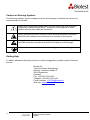
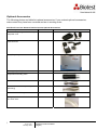
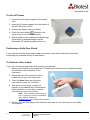
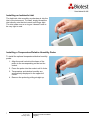
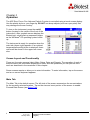
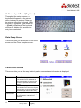
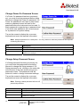
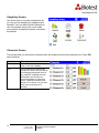
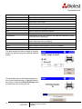
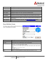
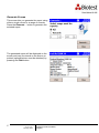
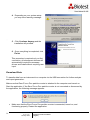
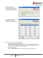
ETP-1.0 en
January 2009
i
ETP-1.0 en
January 2009
Operation and Service Manual
(English)
Operation and Service Manual
(English)
ii
ETP-1.0 en
January 2009
Operation and Service Manual
(English)
ETP-1.0 en
January 2009
Operation and Service Manual
(English)
E-mail address:
[email protected]
SHIP TO/MAIL TO:
Biotest AG
Technical Center Microbiology
Wernher von Braun Straße 9
D-69214 Eppelheim
German
Website:
http://www.biotest.de
Technical Support:
+49.6221.726.5130
Fax:
+49.6221.726.5139
i
ETP-1.0 en
January 2009
Local Technical Support:
Operation and Service Manual
(English)
Manual History
The following is a manual history of the
Particle Counter:
Revision
Date
A
ETP-1.0 en
ii
Handheld Airborne
November 2008
January 2009
ETP-1.0 en
January 2009
Operation and Service Manual
(English)
Warranty
Revision
Copyright
Address
E-mail Address
Limitation of Warranty
and Liability
Service Policy
Trademarks
iii
ETP-1.0 en / January 2009
©Biotest AG / 2009 / All rights reserved.
Biotest AG, Technical Center Microbiology, Wernher von Braun Straße 9,
69214 Eppelheim, Germany
[email protected]
Seller warrants the goods sold hereunder, under normal use and service as
described in the operator's manual, shall be free from defects in workmanship
and material for (24) months, or the length of time specified in the operator's
manual, from the date of shipment to the customer. This warranty period is
inclusive of any statutory warranty. This limited warranty is subject to the
following exclusions:
a.
Parts repaired or replaced as a result of repair services are warranted to
be free from defects in workmanship and material, under normal use, for 90
days from the date of shipment.
b.
Seller does not provide any warranty on finished goods manufactured by
others or on any fuses, batteries or other consumable materials. Only the
original manufacturer's warranty applies.
c.
Unless specifically authorized in a separate writing by Seller, Seller
makes no warranty with respect to, and shall have no liability in connection
with, goods which are incorporated into other products or equipment, or which
are modified by any person other than Seller.
The foregoing is IN LIEU OF all other warranties and is subject to the
LIMITATIONS stated herein. NO OTHER EXPRESS OR IMPLIED
WARRANTY OF FITNESS FOR PARTICULAR PURPOSE OR
MERCHANTABILITY IS MADE.
TO THE EXTENT PERMITTED BY LAW, THE EXCLUSIVE REMEDY OF THE
USER OR BUYER, AND THE LIMIT OF SELLER'S LIABILITY FOR ANY AND
ALL LOSSES, INJURIES, OR DAMAGES CONCERNING THE GOODS
(INCLUDING CLAIMS BASED ON CONTRACT, NEGLIGENCE, TORT,
STRICT LIABILITY OR OTHERWISE) SHALL BE THE RETURN OF GOODS
TO SELLER AND THE REFUND OF THE PURCHASE PRICE, OR, AT THE
OPTION OF SELLER, THE REPAIR OR REPLACEMENT OF THE GOODS.
IN NO EVENT SHALL SELLER BE LIABLE FOR ANY SPECIAL,
CONSEQUENTIAL OR INCIDENTAL DAMAGES. SELLER SHALL NOT BE
RESPONSIBLE FOR INSTALLATION, DISMANTLING OR REINSTALLATION
COSTS OR CHARGES.
No Action, regardless of form, may be brought against Seller more than 12
months after a cause of action has accrued. The goods returned under
warranty to Seller's factory shall be at Buyer's risk of loss, and will be returned,
if at all, at Seller's risk of loss.
Buyer and all users are deemed to have accepted this LIMITATION OF
WARRANTY AND LIABILITY, which contains the complete and exclusive
limited warranty of Seller. This LIMITATION OF WARRANTY AND LIABILITY
may not be amended, modified or its terms waived, except by writing signed by
an Officer of Seller.
Knowing that inoperative or defective instruments are as detrimental to Biotest
as they are to our customers, our service policy is designed to give prompt
attention to any problems. If any malfunction is discovered, please contact your
nearest sales office or representative, or call Biotest's Customer Service
department at +49.6103.801.590
APC, ERGOTOUCH, ERGOTOUCH PRO and ERGOTRAK are trademarks of Biotest
AG. Biotest and the Biotest logo are registered trademarks of Biotest AG.
Microsoft and Excel are registered trademarks of Microsoft Corporation.
ETP-1.0 en
January 2009
Operation and Service Manual
(English)
iv
ETP-1.0 en
January 2009
Operation and Service Manual
(English)
Contents
Manual History ............................................................................................................................ ii
Warranty ..................................................................................................................................... iii
Safety Information .................................................................................................................... vii
Laser Safety..............................................................................................................................vii
Labels ...................................................................................................................................... viii
Description of Caution / Warning Symbols .............................................................................. viii
Caution and Warning Symbols ................................................................................................ viii
Getting Help...............................................................................................................................ix
Chapter 1 Introduction and Unpacking.................................................................................... 1
Unpacking the APC ERGOTOUCH PRO Handheld Airborne Particle Counter ................................. 1
Optional Accessories ...................................................................................................................
Chapter 2 Getting Started ......................................................................................................... 4
Using the Instrument Stand and Stylus...................................................................................... 4
Providing Power......................................................................................................................... 5
To Install the Lithium-ion Battery ............................................................................................... 5
To Use AC Power ...................................................................................................................... 6
Performing a Daily Zero Check.................................................................................................. 6
To Perform a Zero Check .......................................................................................................... 6
Installing an Isokinetic Inlet ........................................................................................................ 7
Installing a Temperature / Relative Humidity Probe................................................................... 7
Chapter 3 Operation .................................................................................................................. 8
Screen Layout and Functionality................................................................................................ 8
Main Tab.................................................................................................................................... 8
Zoomed Data Screen............................................................................................................ 11
Setup Tab ................................................................................................................................ 11
Software Input Panel (Keyboard).......................................................................................... 12
Data Setup Screen................................................................................................................ 12
Count Units Screen............................................................................................................... 12
Clear Samples Screen .......................................................................................................... 13
System Setup Screen ........................................................................................................... 13
Change Power On Password Screen ................................................................................... 14
Change Setup Password Screen.......................................................................................... 14
System Configuration Screen ............................................................................................... 15
Print Setting Screen .............................................................................................................. 15
Pring Schedule Screen ......................................................................................................... 16
Device Setup Screen ............................................................................................................ 16
Date and Time Screen .......................................................................................................... 17
Display Screen...................................................................................................................... 17
v
ETP-1.0 en
January 2009
Operation and Service Manual
(English)
Diagnostics Screen ............................................................................................................... 17
Sampling Screen................................................................................................................... 18
Channels Screen .................................................................................................................. 18
Sample Timing Screen.......................................................................................................... 19
Count Mode Screen .............................................................................................................. 20
Environment Screen ............................................................................................................. 20
Locations Screen .................................................................................................................. 21
Alarms Screen ...................................................................................................................... 22
Recipe Screen ...................................................................................................................... 22
Data Tab .................................................................................................................................. 23
Reports Tab ............................................................................................................................. 25
Room Definition Screen ........................................................................................................ 26
Generate Screen................................................................................................................... 27
Chapter 4 Data Handling ......................................................................................................... 28
USB Computer Communication............................................................................................... 28
Installing Software ................................................................................................................... 28
Procedure ................................................................................................................................ 28
Download Data ........................................................................................................................ 30
Delete Data.............................................................................................................................. 32
Chapter 5 Maintenance............................................................................................................ 33
Maintenance Schedule ............................................................................................................ 33
Daily Zero Check ..................................................................................................................... 33
Cleaning the Instrument Enclosure.......................................................................................... 33
Chapter 6 Troubleshooting ..................................................................................................... 34
Chapter 7 Contacting Customer Service ............................................................................... 36
Contacting Customer Service .................................................................................................. 36
Technical Contacts .................................................................................................................. 36
Returning the APC ERGOTOUCH PRO Handheld Airborne Particle Counter for Service........... 36
Appendix A Specifications...................................................................................................... 37
APC ERGOTOUCH PRO Handheld Airborne Particle Counter ....................................................... 37
Temperature / Relative Humidity Probe Specifications (optional accessory) .......................... 38
vi
ETP-1.0 en
January 2009
Operation and Service Manual
(English)
Safety Information
This section gives instructions to promote safe and proper handling of the
Handheld Airborne Particle Counters.
IMPORTANT
There are no user-serviceable parts inside the instrument. Refer all repair and maintenance to a
qualified factory-authorized technician. All maintenance and repair information in this manual is
included for use by a qualified factory-authorized technician.
Any attempt to open or service the instrument by non-authorized agencies or personnel will void
the warranty.
Laser Safety
The APC ERGOTOUCH PRO Airborne Particle Counter is a handheld Class I laser- based
instrument.
•
During normal operation, the user will not be exposed to laser radiation.
•
Precaution should be taken to avoid exposure to hazardous radiation in the form of
intense, focused, visible light.
•
Exposure to this light may cause blindness.
Take these precautions:
o DO NOT remove any parts from the particle counter unless you are specifically
told to do so in this manual.
o DO NOT remove the housing or covers. There are no user-serviceable
components inside the housing.
WARNING
The use of controls, adjustments, or procedures other than those specified in
this manual may result in exposure to hazardous optical radiation.
vii
ETP-1.0 en
January 2009
Operation and Service Manual
(English)
Labels
Advisory labels and identification labels are attached to the outside of the particle counter
housing and to the optics housing on the inside of the instrument:
1. Serial Number Label
(back panel)
2. Laser Radiation Label
(internal)
DANGER!
VISIBLE LASER RADIATION WHEN
OPEN. AVOID DIRECT
EXPOSURE TO BEAM
WARNING: NO USER SERVICABLE
PARTS INSIDE. REFER SERVICING
TO QUALIFIED PERSONNEL
3. European symbol for
non-disposable item.
Item must be recycled.
Description of Caution/Warning Symbols
Appropriate caution/warning statements are used throughout the manual and on the instrument
that require you to take cautionary measures when working with the instrument:
Caution
!
C a u t i o n
Failure to follow the procedures prescribed in this manual
might result in irreparable equipment damage. Important
information about the operation and maintenance of this
instrument is included in this manual.
!
W A R N I N G
Warning means that unsafe use of the instrument could
result in serious injury to you or cause damage to the
instrument. Follow the procedures prescribed.
Warning
viii
ETP-1.0 en
January 2009
Operation and Service Manual
(English)
Caution or Warning Symbols
The following symbols may accompany cautions and warnings to indicate the nature and
consequences of hazards:
Warns that uninsulated voltage within the instrument may have sufficient
magnitude to cause electric shock. Therefore, it is dangerous to make
contact with any part inside the instrument.
Warns that the instrument contains a laser and that important information
about its safe operation and maintenance is included in the manual.
Warns that the instrument is susceptible to electro-static dissipation (ESD)
and ESD protection procedures should be followed to avoid damage.
Indicates the connector is connected to earth ground and cabinet ground.
Getting Help
To obtain assistance with this product or to submit suggestions, please contact Customer
Service:
Biotest AG
Technical Center Microbiology
Wernher von Braun Straße 9
69214 Eppelheim
Germany
Fax: +49.6221.726.5139
Telephon: +49.6221.726.5130
E-mail Address: [email protected]
Web site: www.biotest.com
ix
ETP-1.0 en
January 2009
Operation and Service Manual
(English)
Chapter 1
Introduction and Unpacking
The APC ERGOTOUCH PRO Airborne Particle Counter is a lightweight, handheld particle counter
with a touch-screen interface. It operates on the included lithium-ion battery or AC power.
The device has a 0.1 ft3 / min (2.83 L / min) flow rate and counts bin sizes from 0.3 to 10 µm. Up
to 10,000 data sets can be downloaded for analysis and reporting using the ERGOTRAK Lite
Data Download Software included with the device.
Typical applications for this particle counter include clean room monitoring, research, exposure
assessment, indoor air quality, filter testing, clearance testing, quality assurance, and
contaminant migration studies. All APC ERGOTOUCH airborne particle counters meet the JIS B
9921: 1997 standard.
Unpacking the
Handheld Airborne Particle Counter
Carefully unpack the APC ERGOTOUCH PRO Airborne Particle Counter from the shipping
container and verify that all the items shown in the photos below and listed in the following
tables are present. Contact Biotest immediately if items are missing or broken:
Qty.
Item Description
Part/Model
1
APC ERGOTOUCH PRO Airborne Particle
Counter
942 550
1
Power Cord
(US)
(UK)
(EURO)
1
AC power adapter
1
Isokinetic inlet
1
Battery pack
1
ETP-1.0 en
January 2009
Operation and Service Manual
(English)
Reference Picture
Qty.
Item Description
1
Computer cable (2 m), USB A to B
1
Stylus
1
HEPA zero filter assembly
1
ERGOTRAK LITE data download utility CD
(includes manual)
1
Operation and Service Manual
1
Calibration certificate
1
Quick Start Guide
2
ETP-1.0 en
January 2009
Part/Model
Reference Picture
(not shown)
(installed on CD)
(not shown)
(installed on CD)
Operation and Service Manual
(English)
Optional Accessories
The following photos and table list optional accessories. If you ordered optional accessories,
make certain they have been received and are in working order:
APC ERGOTOUCH PRO Airborne Particle Counter Optional Accessories
Item Description
Part/Model
Reference Picture
External battery charger with AC adapter
and power cord
External Printer
Heavy Duty Carry case
Printer paper (5 rolls)
(not shown)
Temperature/humidity probe
Stainless Steel Isokinetic inlet
Stainless Steel Isokinetic probe (used
with tubing)
0.1 cfm Barb Inlet Fitting
Tubing, Superthane 1/8-inch ID x ¼-inch
OD, Clear 100 ft
3
ETP-1.0 en
January 2009
Operation and Service Manual
(English)
Chapter 2
Getting Started
This chapter provides information to help you use the APC ERGOTOUCH PRO Airborne Particle
Counter including:
• Using the Instrument Stand and Stylus
• Providing Power
• Performing a Daily Check
• Installing an Isokinetic Inlet
• Installing a Temperature/Relative Humidity Probe
Using the Instrument Stand and Stylus
The APC ERGOTOUCH PRO is equipped with an
integral instrument support stand. To open the
stand, grasp it by the large finger hole and pull it
out until it locks into place. Be careful not to
overextend the stand. To store the stand out of
the way when not in use, simply push the stand
back until it snaps into place.
The APC ERGOTOUCH PRO is also equipped with
a plastic stylus for use with the touch screen
interface. The stylus locks into place in the case
near the top of the unit when not in use.
4
ETP-1.0 en
January 2009
Operation and Service Manual
(English)
Providing Power
The APC ERGOTOUCH PRO may be powered using a removable rechargeable lithium-ion battery,
or through an AC power cord.
Notes:
1. When using AC power, the battery (if installed) charges when the instrument is on, but not
while actively sampling.
2. Removing / changing the lithium-ion battery or disconnecting the AC power does not cause
loss of data.
3. A new battery is installed as part of routine service, if necessary.
To Install the Lithium-ion Battery
1. Remove the battery cover from the back
of the instrument by lightly depressing the
textured tab on the cover located on the
lower left.
2. Slide the lithium-ion battery into the slot,
press down lightly and slide it forward
(toward the top of the unit) until it locks
into place.
3. Replace the battery cover and slide it in
place until you hear a click.
!
!
5
ETP-1.0 en
January 2009
W A R N I N G
The battery supplied by Biotest has built in protection
against explosion and fire hazard. Do not use a substitute.
W A R N I N G
Do not use non-rechargeable batteries in this instrument.
Fire, explosions, or other hazards may result.
Operation and Service Manual
(English)
To Use AC Power
1. Connect the AC power adapter to the power
cord.
2. Insert the AC power adapter into the bottom of
the APC ERGOTOUCH PRO.
3. Connect the power cord to an outlet.
4. Press the on/off button
(located in the
center of the front of the instrument).
5. After a splash screen displays the Biotest logo,
a brief start-up sequence begins as the
Windows® CE operating system boots up.
Performing a Daily Zero Check
A zero check should be performed at least once a day. It should also be performed before
conducting any important testing or certification.
To Perform a Zero Check
Turn on the instrument and wait until the main menu appears.
1. Remove the Isokinetic inlet if attached. The daily zero check cannot be performed when
the isokinetic inlet is attached to the
instrument.
2. Attach the zero filter to the inlet nozzle
located on the top of the instrument.
3. Press the Start button and allow the
instrument to purge for 2 minutes.
4. After the 2-minute purge, continue to
sample. In accordance with JIS standards,
there should be no more than 1 particle
counted at any size in 5 minutes.
Note: If the instrument does not go to
zero (1 particle in 5 min is considered
zero), refer to Chapter 6,
Troubleshooting, for additional information.
5. Remove the zero filter and put the isokinetic inlet back on; the instrument is now ready
for operation.
6
ETP-1.0 en
January 2009
Operation and Service Manual
(English)
Installing an Isokinetic Inlet
The Isokinetic inlet smoothly accelerates air into the
inlet of the instrument. To install, simply thread the
inlet directly onto the inlet nozzle until finger tight.
The inlet seals over an o-ring so it doesn’t have to
be very tight to seal.
Installing a Temperature/Relative Humidity Probe
To install the optional temperature/relative humidity
probe:
1. Align the small red dot at the base of the
probe to the corresponding red dot on the
socket.
2. Press the probe into the socket until it clicks.
3. Temperature and relative humidity are
automatically displayed in the upper-left
corner.
4. Remove the probe by pulling straight up.
7
ETP-1.0 en
January 2009
Operation and Service Manual
(English)
Chapter 3
Operation
The APC ERGOTOUCH PRO Airborne Particle Counter is controlled using a touch screen display.
Use the plastic stylus or your finger tip. DO NOT use sharp objects (such as a pen point) that
may damage the screen overlay.
To turn on the instrument, press the on/off
button (located in the center of the front of the
instrument). After a splash screen displays the
Biotest logo, a brief start-up sequence begins
as the Windows® CE operating system boots
up.
The instrument is ready for operation when the
main tab (shown right) appears. If an optional
temperature/humidity probe is attached, those
values will be shown in the upper-left corner
also.
Screen Layout and Functionality
There are four main screens (tabs): Main, Setup, Data, and Reports. The operation of each of
these screens, the information displayed on them, and the operations you can perform from
each are described in the remainder of this chapter.
Some screens require or allow you to enter information. To enter information, tap on the screen
and an on-screen keyboard appears.
Main Tab
The Main Tab is the default screen. The left side of the screen summarizes the concentrations
for the currently selected location. Tap on the size and count portion of the screen to enable
Zoomed Data Screen (see Setup Tab).
8
ETP-1.0 en
January 2009
Operation and Service Manual
(English)
The display shows:
•
Temperature*
•
Relative humidity*
•
Bin sizes
•
Particle count/concentration
*Temperature and Humidity are displayed only if the
optional T/H probe is installed.
The status bar at the top of the screen shows
the current time and date settings (see the
Setup Tab) and indicates:
Icon
Description
Laser requires service
Sufficient flow through the APC ERGOTOUCH PRO
Insufficient flow through the APC ERGOTOUCH PRO
Operating on AC power, no battery installed
Operating on AC power, battery is installed and charging
Battery charged
Low battery
Battery must be charged
9
ETP-1.0 en
January 2009
Operation and Service Manual
(English)
The right side of the Main Tab shows locations
and other information (delay, cycles, and so
on). These can be configured using the Setup
Tab.
Field
Description
Location
Use this dropdown box to display information about any of the available
locations.
Delay
The initial delay between the time the Start button is pressed and the instrument
begins sampling. Valid only when Automatic mode is selected.
Count
The number of samples that have been taken/the total number of samples. Valid
only when Automatic mode is selected.
Time
The time for each sample. Valid only when Automatic mode is selected.
Hold
The time between samples. Valid only when Automatic mode is selected.
Recs
The total number of records in the database/10000 (maximum number of
records).
Manual/Automatic/Beep
Mode Indicator refers to the “Data Count Mode” (see section below).
Press the Start/Stop button the begin sampling in the configured mode.
Start/Stop may also be entered using the triangle-shaped button above the
power button on the front of the instrument.
Prints the current sample to the optional printer.
10
ETP-1.0 en
January 2009
Operation and Service Manual
(English)
Zoomed Data Screen
The Zoomed Data screen is entered by touching in the size and count part of the main tab
display. The bottom portion of the screen summarizes the concentrations for the currently
selected location. Tap the size and count portion of the display to switch back to the Main Tab
display.
The display shows:
•
Temperature *
•
Relative humidity *
•
Bin sizes
•
Particle count/concentration
* Temperature and Humidity are displayed only if the
optional T/H probe is installed.
.
Field
Description
Prints the current sample to the optional printer.
Location
Label that displays information about the currently selected location.
Press the Start/Stop button the begin sampling in the configured mode.
Setup Tab
The setup tab provides access to the following:
Data Setup
View Count Units and Clear Samples.
System Setup
Change Power On Password, Setup
Password, System Configuration,
Print Settings, and Print Schedule.
Device Setup
Set Visual, Date and Time, and
Diagnostics.
Sampling Setup
Set up Particle Channels, Sample
Timing, Sample Count Mode,
Environment, Locations, and Particle
Channel Alarms.
Recipes
Save a group of settings (recipes) that
you use over and over so you don’t
have to reset individual settings.
11
ETP-1.0 en
January 2009
Operation and Service Manual
(English)
Software Input Panel (Keyboard)
Throughout the setup screens, a
keyboard will appear on the screen
when text may be entered. Data may
be entered using this keyboard. When
the entry is complete, press either the
↵ (Enter) or Esc keys. The keyboard
will then be hidden until another text
entry box is selected.
Data Setup Screen
This screen lets you access the Count Units
screen and the Clear Samples screen:
Count Units Screen
This screen lets you set the way in which particle concentration information is displayed:
Field
Description
Differential
Select to display particle
concentration as a differential Δ
(the total number of counts is the
number of particles between bin
sizes).
Cumulative
Select to display particle
concentration as cumulative Σ (the
total number of counts includes all
particles larger than the bin size).
Concentration
Display concentration in ft3 or m3.
If Beep mode is selected, display
of concentration values is not
allowed.
12
ETP-1.0 en
January 2009
Operation and Service Manual
(English)
Clear Samples Screen
The Clear Samples screen lets you clear all
samples from the internal database. Select
Yes to clear all samples. Select No to return to
the Data Setup screen:
System Setup Screen
From the System Setup screen you can select
(or change) the power on password, set up a
password, select system configuration
parameters, select print settings, and schedule
printing:
13
ETP-1.0 en
January 2009
Operation and Service Manual
(English)
Change Power On Password Screen
If a Power On password has been previously
set, you must enter that password before being
allowed to change the Power On password. If a
Power On password is set, then on instrument
startup a password screen will ask for the
password before the instrument can be used. A
blank password is regarded as no password and
if set as the new password, will not prompt you
for a password on system startup.
Tap on the screen to display the on-screen
keyboard and enter the required information.
Note: Keep the password in a safe place. It is very difficult to reset the password and requires
contacting the factory.
Field
Description
Old Password
Enter your existing password (if one has already been set).
New Password
Enter a new password. The password can be any length and use any characters.
Confirm New Password
Retype the new password then press OK. A confirmation message appears if the
password is changed.
Change Setup Password Screen
If a Setup password has been previously set,
you must enter that password before being
allowed to change the Setup password. If a
Setup password is set, clicking on the setup tab
at the bottom of the main screen brings up a
password screen. That password must be
entered in order to change instrument settings.
Tap on the screen to display the on-screen
keyboard end enter the required information.
Note: Entering a blank password will turn off
password protection.
Field
Description
Old Password
Enter your existing password. (if one has already been set).
New Password
Enter a new password The password can be any length and use any characters.
Confirm New Password
Retype the new password then press OK. A confirmation message appears if the
password is changed.
14
ETP-1.0 en
January 2009
Operation and Service Manual
(English)
System Configuration Screen
Use this screen to set system configuration parameters. Press OK when finished:
Field
Description
Δ and Σ on
Zoom
Select to zoom in on both
cumulative (Σ) and differential (Δ)
counts on the Main Tab. To zoom
the Main Tab, click on the left side
of the Main Tab. (It takes a
moment for the screen to update.)
Click on the screen again to return
to normal view.
Print Settings Screen
A hard copy of a sample set or statistics can be printed from the instrument using an optional
thermal printer. Use this screen to set print parameters. Press OK when finished.
Field
Description
Serial Number
Indicates that the serial number of
the particle counter used to collect
the data will be printed.
Model Name
Indicates that the model number of
the particle counter used to collect
the data will be printed.
Separator
Indicates a line separator will be
printed after the Model Name and
Serial Number in the header of all
printouts
Differential
Indicates that the differential value
of the data will be printed.
Cumulative
Indicates that the cumulative value
of the data will be printed.
Note: Printer paper has a colored strip printed on the last meter of each roll to indicate time to
change the paper roll.
15
ETP-1.0 en
January 2009
Operation and Service Manual
(English)
Print Schedule Screen
Use this screen to schedule automatic printing.
You can choose to either print when an alarm
occurs or print whenever a sample is complete:
Field
Description
Automatic Printing
Enables automatic printing
On Alarm
Print data when an alarm
condition occurs.
On Sample
Print data whenever a sample
completes.
Device Setup Screen
Use this screen to access screens that let you
set or change the date and time, make audio
visual selections, and run diagnostics:
16
ETP-1.0 en
January 2009
Operation and Service Manual
(English)
Date and Time Screen
This screen lets you set the current date and time and set the date format. Press OK when
finished. You can select options using the arrows or tapping on the screen.
Field
Description
Date
Press the down arrow to display a
calendar then select the date from
the calendar.
Time
Select the time component you
want to change (hours; minutes;
seconds) and then use the left and
right arrows to adjust to the current
time.
Date Format
Highlight the date format you want
to use from the list.
24 Hour
Time display is in 24 hour format.
Display Screen
This screen lets you set or change visual
parameters
Field
Description
Screen
Alignment
Press this item to reset the screen
alignment, and follow the
directions on the alignment screen.
Diagnostics Screen
This screen lets you view the system’s
model, serial number, copyright, manufacture
date, calibration date, next calibration date,
firmware version, and USB IP address. Press
Close when finished.
17
ETP-1.0 en
January 2009
Operation and Service Manual
(English)
Sampling Screen
Use this screen to access screens that let
you set up how sampling is displayed and
handled. You can select which channels to
use, the sample timing, the count mode,
environment, sampling locations, and alarm
thresholds.
Channels Screen
This screen lets you choose the channels that are enabled and set their particle size. Press OK
when finished.
Field
Description
Enable
Select the channels you want to
view on the main display.
Size
If the instrument model allows
variable bin sizes, this box allows
for changing the default size for
any channel. Highlight the size
information and use the onscreen keyboard to change its
value. Channels cannot be set
below 0.3 or above 10.0 μm and
they may not overlap one
another.
18
ETP-1.0 en
January 2009
Operation and Service Manual
(English)
Sample Timing Screen
This screen lets you select parameters for
sampling. Use the up and down arrows or
the on-screen keyboard to change or enter
information. These parameters are only valid
when the Model 9306 is running in Automatic
mode. Press OK when finished.
Field
Description
Count
Count is the total number of samples you want collected. In Automatic mode,
a Count value of 0 will cause the instrument to count continuously using the
settings for Delay, Time, and Hold until the Start/Stop button is pressed
again. Use the up and down arrows or the on-screen keyboard to set the
count.
Delay
Delay indicates how long it will be before the first sample is taken.
Remember, it takes approximately 6 seconds for the pump to reach the flow
set point; taking a measurement before the pump is functioning properly may
result in a data error.
Highlight the time component you want to change (hours, minutes, seconds)
and use the up and down arrows or the on-screen keyboard to change the
value.
Hold
Hold indicates how long the instrument pauses between samples. Highlight
the time component you want to change (hours, minutes, seconds) and use
the up and down arrows or the on-screen keyboard to change the value.
Time
Time indicates the duration of each sample run (count particles). Highlight
the time component you want to change (hours, minutes, seconds) and use
the up and down arrows or the on-screen keyboard to change the value.
Volume
Volume sets the volume of air that will pass through the instrument for each
sample. If you select volume, you must select Cubic Feet, Cubic Meters or
Liters for measurement using the arrows.
19
ETP-1.0 en
January 2009
Operation and Service Manual
(English)
Count Mode Screen
Use this screen to set the sample count mode.
Press OK when finished.
Field
Description
Automatic
If you select this mode, the Model 9306 starts counting in
automatic mode when you press the start button according to the
setting on the Sample Timing Screen.
Manual
If you select this mode, the Model 9306 starts sampling
immediately when you press the start button and stops at the end
of the sample time, which is configured on the Sample Timing
Screen.
Beep
If you select this mode, the Model 9306 starts sampling data
immediately and beeps whenever the threshold for the smallest
bin is reached, as specified in Alarms Screen. This can be very
useful when searching for leaks, especially around filters. If this
mode is selected, Display mode is set to Particle Counts while in
Beep mode.
Environment Screen
Use this screen to set the units for
temperature, which is displayed on the Main
Tab, and the printouts when a humidity and
temperature probe is hooked up to the
instrument.
Field
Description
°F
Display temperature in
degrees Fahrenheit.
°C
Display temperature in
degrees Celsius.
20
ETP-1.0 en
January 2009
Operation and Service Manual
(English)
Locations Screen
Associating collected samples with labeled
locations can help keep your data organized.
The APC ERGOTOUCH PRO allows you to
create up to 250 labeled locations (up to 10
characters in length). Use this screen to add,
remove, or modify a location names to the list
of locations.
To modify a location name, highlight the name
in the list, then click the Edit… button. In the
“Enter Location” screen click the edit box in the
middle and use the on-screen keyboard to
modify a location name. (You cannot edit the
empty location). Click OK when finished.
To add a location, click on the Add… button .
In the “Add Location” screen click in the edit
box in the middle and use the on-screen
keyboard to add a location name. Click OK
when finished.
To remove a location, click on location to be
removed and click the Remove button.
Back in the main Locations screen, after all
editing has been completed, press OK when
finished.
21
ETP-1.0 en
January 2009
Operation and Service Manual
(English)
Alarms Screen
Use this screen to set the alarm threshold for each channel. Press OK when finished.
Field
Description
Enable
Select the channels on which
you want to enable alarms.
Threshold
To change the threshold for
any channel, click the up and
down arrows for that channel or
use the on-screen keyboard to
change its value. The threshold
value units use the current
display Count Units (see Count
Units Screen).
When a channel value exceeds the threshold value you set, the channel data is highlighted in
red on the Main tab, an audible alarm sounds, and the alarm icon appears on the Main tab.
To clear the alarm, click the alarm icon
In addition, the record is printed if you have selected
that option on the Print Schedule Screen.
Recipe Screen
Use this screen to load and save recipes.
Recipes let you save a group of settings
(recipe) that you use over and over so you
don’t have to reset individual settings. There
may be up to 100 recipes stored in the unit.
22
ETP-1.0 en
January 2009
Operation and Service Manual
(English)
Field
Description
Save
When you select Save, a new window opens that lets you enter a name for the
recipe you want to save. The settings/parameters that are saved include:
For each channel (1-6):
• Alarm setting (on/off)
• Alarm threshold (value)
• Channel setting (enabled/disabled)
• Channel threshold (value)
Sample Timing settings
• Count mode
• Count total
• Start delay (in secs)
• Hold delay (in secs)
• Sample time (in secs)
Count Mode/Units Settings
• Display normalized
• Units (count, ft3 or m3)
• Cumulative/Differential
• Volume units
Printing settings
• Auto print and mode
• Print cumulative/differential
• Print reverse setting (if supported)
• Print model, separator, serial number
Save As
When you select Save As, a new window opens that lets you enter a name for the
recipe you want to save.
Load
Highlight the recipe you want to load and press Load. The settings/parameters are
reset to the values of that recipe.
Delete
Highlight the recipe you want to delete and press Delete. The recipe is deleted.
Data Tab
The Data tab lets you preview data that has
been collected. Use the elevator (slide) on the
right to scroll though the records. The record
number is displayed at the bottom of the tab.
As each record displays, its data and relevant
parameters are displayed.
23
ETP-1.0 en
January 2009
Operation and Service Manual
(English)
Field
3
Description
3
#, ft , m
Button used to change between counts and concentration displays.
Size µm
Channel size.
Δ
Differential concentration.
Σ
Cumulative concentration.
Location
Location where the data was collected.
Sample
Duration of the sampling period.
Date
Date on which the data was collected.
Time
Time at which data was collected.
Temperature
Temperature at the end of the time the data was collected (if probe
connected during sampling).
Humidity
Humidity level at the end of the time the data was collected (if
probe connected during sampling).
Flow
Status of the flow.
Alarm
Alarm threshold was triggered (YES) or not (NONE).
Laser
Status of the laser.
The print button will allow a range of sample
data to be printed using the optional external
printer.
The print data screen will show progress on
the current selected range of sample data to
be printed. Press the Cancel Printing button
to cancel the rest of the print job.
24
ETP-1.0 en
January 2009
Operation and Service Manual
(English)
Reports Tab
Use this screen to select various standard
reports for viewing and printing
The standard reports are shown below:
25
ETP-1.0 en
January 2009
Operation and Service Manual
(English)
Field
Description
Room Area
Displays the area of the room in ft2 or m2.
Class Level
Depends on the report definition, see below.
Air Flow
Displays the airflow characteristics of the room.
Room Status
Displays the status of the room. See Room Definition below.
Min Locations
Displays the minimum number of locations that must be sampled in the room.
Min Samples
Displays the minimum number of samples that must be taken at each location.
Allowable Sizes
Allowable channel sizes for the selected Class Level for that Standard.
Minimum Volume
Displays the minimum volume (in cubic feet or meters) that must be sampled on
each channel.
Room Definition
Press to set definitions for the room. (See Room Definition Screen below.)
Generate
Select to print a single record or a range of records. (See Print Screen below.)
Room Definition Screen
Use this screen to define specific values for the
room. Press OK when finished:
Field
Description
Room Status
Select the room status: As Built, At Rest, or Operational.
Air Flow
Select the air flow: Unidirectional or Non-unidirectional.
Class
Select the class of the room: The class is dependent on the standard:
FED FT3: 1, 20, 100,1000,10000, 100000
FED M3: M1.0, M1.5, M2.0, M3.0, M3.5, M4.0, M4.5, M5.0, M5.5, M6.0, M6.5,
M7.0
ISO14644-1: 1, 2, 3, 4, 5, 6, 7, 8, 9
EC GMP: A, B, C, D
Area
Use the on-screen keyboard to enter the area of the room in ft2 or m3.
26
ETP-1.0 en
January 2009
Operation and Service Manual
(English)
Generate Screen
This screen lets you generate the report using
either a single record or a range of records.
Press the Generate… button to generate the
selected report.
The generated report will be displayed on the
screen and may be viewed on the screen or
printed (optional printer must be attached) by
pressing the Print button.
27
ETP-1.0 en
January 2009
Operation and Service Manual
(English)
Chapter 4
Data Handling
USB Computer Communication
The APC ERGOTOUCH PRO Airborne Particle Counter is equipped with a USB compatible cable
for uploading and downloading information to a PC. The cable plugs into the right side of the
instrument.
Installing Software
The ERGOTRAK Lite Data Transfer utility comes on a CD that loads software and
communications drivers for the particle counter. To install the software, insert the CD into your
computer drive and follow the instructions. Installation consists of two parts:
•
•
28
Installation of ERGOTRAK Lite software.
Run “setup.exe” from the provided CD and follow on-screen instructions.
Installation of USB NDIS driver. This installation is executed transparently during the
setup process and does not require user input. Once installation is finished, drivers are
ready for use. When the APC ERGOTOUCH PRO particle counter is connected for the first
time, system will automatically detect the device and will start driver installation process.
ETP-1.0 en
January 2009
Operation and Service Manual
(English)
Procedure
1. When asked if Windows update
should be used to download
necessary software, select “No, not
this time” and click Next.
2. Select “Install the software
automatically (Recommended)” and
click Next.
3. Hardware Wizard will search for the
driver and locate it in
\System32\drivers directory.
Once that is done, the following
screen will appear:
29
ETP-1.0 en
January 2009
Operation and Service Manual
(English)
4. Depending on your system setup
you may see a warning message:
5. Click Continue Anyway and the
installation will proceed.
6. Once everything is completed, click
Finish.
This procedure is required only on first
connection, all subsequent devices will
automatically locate the necessary
drivers and install without requiring user
input.
Download Data
To transfer data from an instrument to a computer via the USB connection for further analysis
and report generation:
Make sure that ERGOTOUCH PRO particle counter is attached to the computer and turned on.
Start the application. If the ERGOTOUCH PRO particle counter is not connected or discovered by
the application, the following message appears:
•
30
Make sure that the ERGOTOUCH PRO particle counter is connected, turned on, and
functioning properly. Restart the application.
ETP-1.0 en
January 2009
Operation and Service Manual
(English)
•
If communication with
ERGOTOUCH PRO particle
counter has been established,
the following screen appears:
•
Once data is successfully
downloaded, the main
application screen will appear:
1. There are two options for downloading data:
31
•
Download only user selected records:
Hold down the CTRL key and use the mouse to click on the records you want to
retrieve. When you have selected the records, press the Get Selected button to
retrieve only the selected records from the device.
•
Download all records:
Press the Download All button to retrieve all the records from the device.
ETP-1.0 en
January 2009
Operation and Service Manual
(English)
2. After you press either the Get
Selected or Download All buttons,
the following dialog appears to allow
you to select the folder where data will
be saved:
•
•
•
To cancel the data transfer, select
Cancel
To accept the data transfer, enter the
file name under which data will be
saved and select Save.
Data is stored in a .CSV file that can
be opened by most spreadsheet
programs such as Microsoft® Excel®
spreadsheet software.
Delete Data
In order to delete data from the device click Delete Records button. The following warning will
appear:
If Yes is selected, ERGOTRAK
Lite software will erase data
from the device and also from
application memory.
!
32
ETP-1.0 en
January 2009
W A R N I N G
Deleting data is an irreversible operation. Download and save
data before deleting in order to have a copy for future use.
Operation and Service Manual
(English)
Chapter 5
Maintenance
Note
There are no user-serviceable parts inside this instrument. Opening the instrument case may void
the warranty. Biotest recommends that you return the APC ERGOTOUCH PRO Airborne Particle
Counter to the factory for any required maintenance or service not described in this manual.
Maintenance Schedule
Biotest recommends annual factory cleaning and calibration for the APC ERGOTOUCH PRO
Airborne Particle Counter. See Chapter 7, "Contacting Customer Service" for service/calibration.
Recommended Field Maintenance Schedule
Item
Frequency
Daily zero check
Daily (or before each use).
Factory cleaning and calibration
Annually.
Cleaning the instrument enclosure
As needed
Daily Zero Check
The daily zero check ensures that the instrument is properly assembled and free from leaks,
residual particles and electronic noise. Please see Chapter 2, “Getting Started” for detailed
instructions on performing the zero check.
Cleaning the Instrument Enclosure
To clean the enclosure, dampen a lint-free cloth and gently wipe the surface until surface
contamination is removed.
33
ETP-1.0 en
January 2009
Operation and Service Manual
(English)
Chapter 6
Troubleshooting
Symptom
Possible Cause
Corrective Action
Counts are too low
•
•
Operate instrument within
specifications
•
Return to factory for service
•
Return to factory for service
•
Return to factory for service
•
Instrument is being operated
outside temperature or
relative humidity
specifications.
Internal parts have been
damaged because
instrument was stored at a
temperature greater than
122 °F (50 °C).
Instrument has
contamination on the optics
due to condensation or
excessive loading
Laser or pump control is
damaged
Unit is due for calibration
•
Return to factory for service
•
Battery is dead
•
•
AC cord is not plugged into
unit
•
Recharge battery or connect
to AC power
Connect AC cord
•
HEPA filter is not connected
properly and room air is
leaking into the HEPA filter
assembly
•
•
Residual particles from
previous samples are
shedding off internal parts
and into the optics
An internal component has
been damaged due to
operation outside of
temperature specifications or
one ore more excessive
bumps or jolts, and
electronic noise is inducing
false counts
A leak has developed in the
aerosol flow path
Internal optics have become
dirty
•
The unit must be turned on
but not in sampling mode for
the battery to charge
•
•
•
Instrument does not turn on
Instrument does not meet zero
count specification (<1
particle/5 mins)
•
•
•
Battery does not charge
34
ETP-1.0 en
January 2009
•
Operation and Service Manual
(English)
•
Check that the HEPA filter
has been tightly connected
to the inlet. Check that
rubber o-ring (black) on the
inlet is in place
Purge instrument by running
the instrument for 10–15
minutes before attempting
zero count test
Return to factory for service
•
Return to factory for service
•
Return to factory for service
•
Turn on unit.
Symptom
Possible Cause
Corrective Action
LOW BATTERY ERROR
•
Low battery
•
Recharge battery or connect
AC cord
PHOTODETECTOR ERROR
•
Direct light is entering the
aerosol inlet
Laser has become
misaligned due to excessive
bumps or jolts
Internal optics have become
dirty
•
•
Remove instrument from
direct light
Return to factory for service
•
Return to factory for service
•
•
SYSTEM ERROR
•
Information is not being read
properly by microprocessor
•
Restart instrument. If
problem persists, contact
Biotest technical support
TEMPERATURE HUMIDITY
PROBE ERROR
•
Temperature/RH probe was
not recognized
•
Detach and reconnect probe.
If problem persists, contact
Biotest technical support
FLOW ERROR
•
Instrument was unable to
control flow rate (if any
tubing is connected to
particle counter)
Pressure drop across inlet
may be too large
•
Restart measurement
•
Lessen pressure drop across
inlet by using larger diameter
tubing, less tubing, and/or
adding a bleed valve
Do not subject the unit to
other than ambient pressure
conditions
•
LASER POWER WARNING
35
ETP-1.0 en
January 2009
•
Inlet not at ambient pressure
•
Laser power has fallen
outside of specification
Operation and Service Manual
(English)
•
•
Return to factory for service
Chapter 7
Contacting Customer Service
This chapter gives directions for contacting people at Biotest AG for technical information and
directions for returning the APC ERGOTOUCH PRO Airborne Particle Counter for service.
Technical Contacts
•
If you have any difficulty setting up or operating the APC ERGOTOUCH PRO, or if you have
technical or application questions about this system, contact an applications engineer at
Biotest AG, +49.6221.726.5130 or e-mail [email protected]
•
If the APC ERGOTOUCH PRO, does not operate properly, or if you are returning the
instrument for service, visit our website at http://www.biotest.com, or contact Biotest
Customer Service at +49.6103.801.496.
•
Call your local Biotest Subsidiary or Representative.
Returning the APC ERGOTOUCH PRO Airborne Particle Counter for Service
Visit our website at http://www.biotest.com or call Biotest Technical Support at
+49.6221.726.5130 or Biotest Customer Service at +49.6103.801.590 for specific return
instructions. Customer Service will need this information when you call:
•
The instrument model number
•
The instrument serial number
•
A purchase order number (unless under warranty)
•
A billing address
•
A shipping address
Use the original packing material to return the instrument to Biotest. If you no longer have the
original packing material, seal off any ports to prevent debris from entering the instrument and
ensure that the display and the connectors on the instrument front and back panels are
protected.
36
ETP-1.0 en
January 2009
Operation and Service Manual
(English)
APPENDIX A
Specifications
All specifications meet or exceed JIS B 9921. They are subject to change without notice.
Size Range
0.3–10 µm
Channel Sizes
Standard:
0.3, 0.5, 1.0, 3.0, 5.0, 10.0 μm
Counting Efficiency
50% @ 0.3 μm; 100% for particles > 0.45 μm (per JIS)
Concentration Limits
2,000,000 particles/ft3 @ 5% coincidence loss
Light Source
Laser diode
Zero Count Level
<1 count/5 minutes (<2 particles/ft3) Meets JIS B9921
Flow Rate
0.1 CFM (2.83 L/min) with ±5% accuracy
Flow Control
Automatic
Calibration
NIST traceable
Sample Probe/Tubing
Isokinetic sampling probe
Sampling Modes
Manual, automatic, beep, concentration and
cumulative/differential
Sampling Time
1 second to 99 min 59 sec
Sampling Frequency
1 to 999 cycles or continuous
Sample Output
Internal HEPA filter
Vacuum Source
Internal pump
Communication Mode
RS-232, USB
Data Storage
10,000 samples
Data Security
Password protected
External Alarm
Internal audible alarm. Indicators for counts, low battery, and
sensor failure
Environmental Sensors
Optional temperature/RH probe supported
Display
QVGA 3.7-inch touch screen with Windows CE
Languages
English
Reports
ISO-14644-1, FS-209E & EC GMP
Printer
Optional external printer supported
External Surface
High impact injection molded plastic
Power
110 to 240 VAC 50 to 60 Hz Universal in-line power supply
Battery
Removable Li-Ion
Battery Life
Up to 3 hours of continuous use
Recharge Time
3 hours
Dimensions (L x W x H)
25.4 x 11.4 x 7.6 cm (10 x 4.5 x 3 in.)
Weight
1.0 kg (2.2 lbs) with battery
Warranty
2 years. Extended warranties available
37
ETP-1.0 en
January 2009
Operation and Service Manual
(English)
Operating Conditions
5°C to 35°C; 20% to 95% non-condensing relative humidity
Storage Conditions
0°C to 50°C; Up to 98% non-condensing relative humidity
Included Accessories
Power supply, power cord, battery, isokinetic inlet, stylus, purge
filter, ERGOTRAK Lite data download software, operational
manual on CD, computer cable, calibration certificate, and Quick
Start Guide.
Optional Accessories
Temp R/H probe, stainless steel isokinetic inlet and probe,
tubing, barbed inlet fitting, printer, printer paper, carrying case
and external battery charger
Temperature / RH Probe Specifications (optional accessory)
Temperature
Range .......................
Accuracy...................
32 to 115ºF (0 to 45ºC)
±2ºF (±1ºC)
Relative Humidity
Range .......................
Accuracy...................
10 to 90% RH
±5% RH
38
ETP-1.0 en
January 2009
Operation and Service Manual
(English)