1
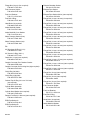
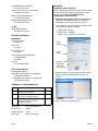
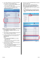
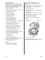
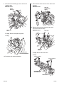
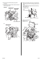
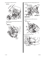
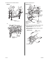
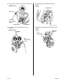
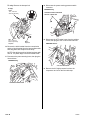
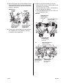
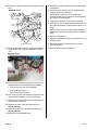
Service Bulletin Applies To: 13-024 2013 MDX – From VIN 2HNYD2...DH500001 thru 2HNYD2...DH525406 2013 TL SH-AWD – From VIN 19UUA9...DA000001 thru 19UUA9...DA005530 2013 ZDX – From VIN 2YNYB1...DH500001 thru 2YNYB1...DH500365 August 23, 2013 MIL Comes On With DTCs P0300 Thru P0306 (Supersedes 13-024, dated June 5, 2013; see REVISION SUMMARY) REVISION SUMMARY This bulletin has been revised extensively. American Honda recommends that you review the bulletin thoroughly. SYMPTOM The MIL comes on with at least one of the following DTCs: • • • • • • • P0300 Random Misfire Detected P0301 No. 1 Cylinder Misfire Detected P0302 No. 2 Cylinder Misfire Detected P0303 No. 3 Cylinder Misfire Detected P0304 No. 4 Cylinder Misfire Detected P0305 No. 5 Cylinder Misfire Detected P0306 No. 6 Cylinder Misfire Detected Cylinder Block Assy (MDX): P/N 10002–RYE–A10 Cylinder Block Assy (ZDX): P/N 10002–RP6–A01 EGR Pipe Gasket A: P/N 18716–R70–A01 EGR Pipe Gasket B: P/N 18719–R70–A01 CORRECTIVE ACTION Inspect the vehicle and, if necessary, replace the engine block. Exhaust Chamber Gasket: P/N 18115–R70–A01 Exhaust Pipe Gasket: P/N 18302–SP0–003 Exhaust Pipe Gasket (Ishino) (two required): P/N 18212–SA7–003 Flange Bolt (10 mm x 20 mm) (six required): P/N 90163–S5A–000 Flange Bolt (10 mm x 25 mm) (four required): P/N 90167–SAA–010 PARTS INFORMATION Flange Bolt (10 mm x 25 mm) (four required): P/N 90113–SV3–A00 MDX/ZDX: A/C Discharge O-Ring (1/2 in.): P/N 80872–ST7–000 Flange Bolt (10 mm x 35 mm) (two required): P/N 90163–SDA–A01 A/C Suction O-Ring (5/8 in.): P/N 80871–ST7–000 Flange Bolt (12 mm x 30 mm) (two required): P/N 90169–S3V–A00 Castle Nut (14 mm) (two required): P/N 90365–STX–A00 Flange Bolt (12 mm x 65 mm) (two required): P/N 95701–12065–08 Catalytic Converter Pre-Chamber Gasket: P/N 18393–SDB–A00 Catalytic Converter Self Locking Nut (eight required): P/N 90212–RCA–A01 2013 American Honda Motor Co., Inc. – All Rights Reserved Coolant Pipe O-Ring (31.2 x 4.1 mm) (two required): P/N 91314–PH7–003 Cylinder Head Gasket (two required): P/N 12251–RKG–004 POSSIBLE CAUSE The cylinder bore may be out of round, causing low compression. Circlip Ring (left side): P/N 44319–STX–A01 Circlip Ring (right side): P/N 44319–STX–A60 Flange Bolt (12 mm x 115 mm): P/N 90161–SZA–A00 Flange Bolt (14 mm x 125 mm): P/N 90161–S0X–A00 Flange Nut (12 mm) (two required): P/N 90362–SZA–A00 BTB 49599-50056 REV1 (1308) 1 of 18 CLIENT INFORMATION: The information in this bulletin is intended for use only by skilled technicians who have the proper tools, equipment, and training to correctly and safely maintain your vehicle. These procedures should not be attempted by “do-it-yourselfers,” and you should not assume this bulletin applies to your vehicle, or that your vehicle has the condition described. To determine whether this information applies, contact an authorized Acura automobile dealer. Flange Nut (12 mm) (four required): P/N 90371–TK4–A00 Exhaust Chamber Gasket: P/N 18115–R70–A01 Fuel Connector Holder: P/N 16726–RYE–A01 Exhaust Pipe Gasket: P/N 18302–SP0–003 Fuel Line Retainer: P/N 17711–SOX–931 Exhaust Pipe Gasket (Ishino) (two required): P/N 18212–SA7–003 Fuel Rail O-Ring: P/N 91301–PLC–000 Flange Bolt (10 mm x 20 mm) (six required): P/N 90163–S5A–000 Head Bolts (16 required): P/N 90005–PAA–A01 Flange Bolt (10 mm x 30 mm) (two required): P/N 90163–SDB–A00 Intake Manifold Gasket: P/N 17105–RCJ–A01 Flange Bolt (10 mm x 34 mm) (two required): P/N 90170–SDA–A01 Intake Manifold Cover Gasket: P/N 17146–R70–A01 Flange Bolt (10 mm x 35 mm) (two required): P/N 90163–SDA–A01 Water Passage Gasket (front): P/N 19411–P8A–A03 Flange Bolt (10 mm x 80 mm) (two required): P/N 90162–S5A–000 Water Passage Gasket (rear): P/N 19412–P8A–A02 Flange Bolt (12 mm x 25 mm) (two required): P/N 95701-12025-08 TL: Flange Bolt (12 mm x 30 mm) (two required): P/N 90176–SKN–000 A/C Discharge O-Ring (1/2 in.): P/N 80872–ST7–000 A/C Suction O-Ring (5/8 in.): P/N 80871–ST7–000 Castle Nut (14 mm) (two required): P/N 90363–TK4–A01 Catalytic Converter Pre-Chamber Gasket: P/N 18393–SDB–A00 Catalytic Converter Self Locking Nut (eight required): P/N 90212–RCA–A01 Circlip Ring (left side): P/N 44319–SJA–A00 Circlip Ring (right side): P/N 44319–STX–A60 Coolant Pipe O-Ring (31.2 mm X 4.1mm) (two required): P/N 91314–PH7–003 Cylinder Block Assembly: P/N 10002–RK2–A03 Cylinder Head Gasket (two required): P/N 12251–RKG–004 Damper Fork Bolt (12 X98 mm) (two required): P/N 90121–SM4–010 EGR Pipe Gasket A: P/N 18716–R70–A01 EGR Pipe Gasket B: P/N 18719–R70–A01 2 of 18 Flange Bolt (12 mm x 33 mm) (two required): P/N 90186–SDA–A00 Flange Bolt (12 mm x 45 mm) (two required): P/N 90161–SDA–A01 Flange Bolt (12 mm x 75 mm) (two required): P/N 90396–S5A–010 Flange Bolt (14 mm x 135 mm) (two required): P/N 90176–SDA–A00 Flange Bolt (14 mm x 150 mm) (two required): P/N 90177–SDA–A00 Flange Nut (12 mm) (two required): P/N 90362–SZA–A00 Flange Nut (12 mm) (two required): P/N 94050–12080 Flange Nut (12 mm) (four required): P/N 90371–TK4–A00 Fuel Connector Holder: P/N 16726–RYE–A01 Fuel Line Retainer: P/N 17711–SOX–931 Fuel Rail O-Ring: P/N 91301–PLC–000 Head Bolts (16 required): P/N 90005–PAA–A01 Intake Manifold Gasket: P/N 17105–RCJ–A01 13-024 Intake Manifold Cover Gasket: P/N 17146–R70–A01 DIAGNOSIS Total Misfire Value Inspection NOTE: If the MIL comes on in an unsold vehicle, make sure the vehicle has at least a quarter tank of fresh, premium fuel, and do this inspection after completing the TQI procedures. Self Lock Nut (12 mm) (two required): P/N 90215–SB0–003 Water Passage Gasket (front): P/N 19411–P8A–A03 1. Make sure the engine is cold; connect the HDS to the vehicle and check that the ECT SENSOR 1 temperature value is less than 100 °F (38 °C). Water Passage Gasket (rear): P/N 19412–P8A–A02 2. Go to PGM-FI, then select Snapshot. Set the HDS to the following snapshot settings: • Trigger Type - Manual • Record Time - 3 minutes • Trigger Point - 0 (all the way to the left) TL M/T: Circlip Ring (left side): P/N 44319–STX–A01 REQUIRED MATERIALS MDX/ZDX/TL Antifreeze Coolant: (3 gallons) Select “Manual”. ATF Fluid: (4 quarts) 5W-20 Engine Oil: (5 quarts) Select “3 Min”. Power Steering Fluid (MDX/ZDX): P/N 08206-9002 (3 bottles) Oil Filter: P/N 15400-PLM-A02 Slide the trigger point scale all the way to the left. TOOL INFORMATION Steering Wheel Holder: Lower Ball Joint Remover (or equivalent): T/N 07MAC–SL0A102 Tie Rod Ball Joint Remover (or equivalent): T/N 07MAC-SL0A202 3. Start the engine, then start recording data. Let the engine idle with the transmission in Park for 3 minutes. WARRANTY CLAIM INFORMATION OP# Description 1115A3 Connect the HDS and do the total misfire value inspection. 0.3 hr A Do an engine compression test and, if necessary, misfire B inspection. 0.9 hr 1121F6 Replace the engine block. (DPSM authorization required. Includes alignment). Failed Part: P/N 10002-RYE-A10 Defect Code: 09999 Symptom Code: 09107 Skill Level: Repair Technician 13-024 FRT 13.8 hrs 4. After 3 minutes, turn the engine off. 3 of 18 5. In the OBS snapshot file, scroll down and review each cylinder’s TOTAL MISFIRE value. • If each of the cylinders TOTAL MISFIRE values are 5 or less, the vehicle is OK. • If any cylinder’s TOTAL MISFIRE value is more than 5, go to Engine Compression Test. 5. Check each cylinder’s MISFIRE B data recorded in the OBS snapshot file. NOTE: Do the engine compression test first because if you only check the MISFIRE B value, you may not properly diagnose the vehicle. • If the MISFIRE B value is 10 or less, the vehicle is OK. • If the MISFIRE B value on any cylinder is more than 10, this bulletin does not apply. Continue with normal troubleshooting for the cause of the misfire. Engine Compression Test and Misfire B Inspection 1. Let the engine cool down so that the ECT SENSOR 1 temperature value is less than 100 °F (38 °C). 2. Print out page 1 of the job aid Engine Compression Test and Cylinder Leakage Test (V6). 3. Do steps 2 through 12 from the job aid, and record the compression value for each cylinder in the space provided. NOTE: • Do not warm up the engine for the engine compression test. • Make sure that you use a compression gauge that measures up to 300 psi. 4. Find the amount of variation between the highest and lowest cylinder reading. • If the variation between the cylinders is 30 PSI or more, go to REPAIR PROCEDURE. • If the variation between the cylinders is 29 PSI or less, go to step 5. 4 of 18 13-024 REPAIR PROCEDURE The following electronic service manual procedures have been used in full or in part within this service bulletin. For more detail on these procedures, and torque specifications for some components, refer to the appropriate electronic service manual. Engine/transmission assembly removal • Use fender covers to avoid damaging painted surfaces. • To avoid damaging any wires and terminals, unplug the circuit connectors carefully while holding the connector portion. • • • • • • • • • • • • • • • • • Engine Oil Replacement Battery Terminal Disconnection and Reconnection A/C System Recovery/Charging Fuel Pressure Relieving Shift Cable Replacement Steering Gearbox Removal Transfer Assembly Removal Coolant Replacement Drive Belt Removal/Installation Front Undercover Replacement Splash Shield Replacement Hydraulic Power Steering Fluid Check/Replacement Air Cleaner Removal/Installation Fuel Line/Quick-Connect Fitting Removal Front Bulkhead Cover Replacement Front Stabilizer Link Removal/Installation Front Knuckle/ Hub Bearing Unit Replacement 1. Relieve the fuel pressure. • • • • • • • Cylinder Head Cover Removal Intake Manifold Removal and Installation Warm Up TWC Removal/Installation Transmission Shift Cable Removal and Installation Cylinder Head Removal and Installation Cam Chain Removal and Installation Valve Adjustment • • • • • Propeller Shaft Removal Alternator Removal and Installation Ignition coil and Spark Plug Removal and Installation Exhaust Pipe and Muffler Replacement A/C System Evacuation 2. Wait until the engine is cool, then carefully remove the radiator cap. 3. Loosen the drain plug on the radiator, and drain the engine coolant. 4. Drain the power steering system fluid, then plug the fluid reservoir and the return hose. 5. Do the battery removal procedure. 6. Remove the engine cover. (TL has multiple covers). MDX/ZDX shown: ENGINE COVER 7. Evacuate the A/C system. 8. Separate the A/C suction line at the right strut tower junction and cover the lines with tape. TL Only: • Strut Brace Removal/Installation • Damper Fork Removal/Installation 13-024 5 of 18 9. Disconnect the breather pipe, then remove the intake air duct. 11. Disconnect the cable from the main under-hood fuse box. MDX/ZDX shown: MDX/ZDX shown: INTAKE AIR DUCT POSITIVE ALTERNATOR CABLE 12. Remove the main under-hood fuse box, then remove the harness clamp. BREATHER PIPE MDX/ZDX shown: FUSE BOX TL only: Remove the splash separator. TL only: HARNESS CLAMP AIR INTAKE DUCT SPLASH SEPARATOR TL only: Remove the strut brace. TL only: 10. Remove the air cleaner assembly. 22 N.m (16 lb-ft) 22 N.m (16 lb-ft) BRAKE BOOSTER VACUUM HOSE STRUT BRACE 6 of 18 13-024 13. Remove the harness clamps, then remove the battery base. TL only: Remove the harness clamp, then disconnect the harness connectors. TL only: MDX/ZDX: HARNESS CONNECTORS BOLTS 22 N.m (16 lb-ft) BATTERY BASE CLAMP 14. Remove the transmission shift cable from the transmission only. HARNESS CLAMPS TL: 22 N.m (16 lb-ft) 15. Remove the quick-connect fitting cover, then disconnect the fuel feed hose. MDX/ZDX: QUICK-CONNECT FITTING COVER FUEL FEED HOSE BATTERY BASE 22 N.m (16 lb-ft) TL: HARNESS CLAMPS QUICK-CONNECT FITTING COVER HARNESS CLAMPS (M/T only.) 9.8 N.m (7.2 lb-ft) 13-024 7 of 18 16. Disconnect the EVAP canister purge valve connector. 17. Disconnect the brake booster vacuum hose and EVAP canister hose. MDX/ZDX: BRAKE BOOSTER EVAP CANISTER VACUUM HOSE PURGE VALVE CONNECTOR 18. Remove the steering joint cover, then disconnect the steering joint from the steering gearbox pinion shaft. NOTE: Hold the steering wheel with the steering wheel holder tool. MDX/ZDX shown: BOLT 22 N.m (16 lb-ft) BOLT HOLE GROOVE BOLT 22 N.m (16 lb-ft) 19. Remove the PCM cover. EVAP CANISTER HOSE MDX/ZDX shown: TL: COVER BRAKE BOOSTER VACUUM HOSE BRACKET CLIP A/C DISCHARGE LINE PCM EVAP CANISTER HOSE 8 of 18 A/C SUCTION LINE MOUNTING BRACKET BOLT 13-024 20. Disconnect the PCM connectors. MDX/ZDX: 21. Disconnect the power steering pump inlet hose. MDX/ZDX: POWER STEERING PUMP OUTLET HOSE 12 N.m (1.2 lb-ft) 11 N.m (1.1 lb-ft) O-RING Replace. POWER STEERING HOSE CLAMP POWER STEERING PUMP INLET HOSE PCM CONNECTORS TLonly: Disconnect the EPS connectors. TL only: TL: Remove the harness clamp and disconnect the PCM connectors. EPS CONNECTORS TL: ECM/PCM CONNECTORS 22. Disconnect the heater hoses. MDX/ZDX shown: HARNESS CLAMP HEATER HOSES 13-024 9 of 18 23. Disconnect the upper radiator hose and the lower radiator hose at the engine. TL only: Remove the upper transmission mount bracket mounting bolts. NOTE: Do not remove the center mount bolt from the upper transmission mount. If the bolt is removed, the upper transmission mount must be replaced as an assembly. MDX/ZDX shown: TL only: M/T model UPPER RADIATOR HOSE 59 N.m (43 lb-ft) Replace. Do not remove the center bolt. LOWER RADIATOR HOSE 24. Remove the mounting bolts from the upper half of the side engine mount bracket. MDX/ZDX: BOLTS 44 N.m (33 lb-ft) A/T model 59 N.m (43 lb-ft) Replace. TL: 54 N.m (40 lb-ft) Replace. Do not remove the center bolt. 25. Make sure the engine/transmission is completely free of any vacuum hoses, fuel hoses, coolant hoses, and electrical connections. 26. Raise the vehicle on the lift. 27. Remove the front wheels. 28. Remove the splash shield and the front undercover. 29. Drain the engine oil. 30. Drain the ATF. 10 of 18 13-024 31. Remove the front subframe stiffener. 32. Remove exhaust pipe A. MDX/ZDX shown: MDX/ZDX: GASKET Replace. GASKETS Replace. EXHAUST PIPE A BOLTS 54 N.m (40 lb-ft) SELF-LOCKING NUTS 54 N.m (40 lb-ft) Replace. TL: SELF-LOCKING NUTS 54 N.m (40 lb-ft) 54 N.m (40 lb-ft) Replace. 33. Remove the propeller shaft. Make a reference mark across the No.1 propeller shaft and transfer companion flange. NOTE: You will need reference marks to reinstall the propeller shaft. MDX/ZDX shown: BOLTS (5) BOLT 72 N.m (53 lb-ft) Replace. SUBFRAME STIFFENER 54 N.m (40 lb-ft) Replace. REFERENCE MARK 13-024 11 of 18 34. Remove the torque converter cover from the transmission. 37. Separate the stabilizer links from the dampers. MDX/ZDX: MDX/ZDX shown: DRIVE PLATE BOLTS (8) DAMPER 12 N.m (8.7 lb-ft) 12 N.m (8.7 lb-ft) STABILIZER LINK FLANGE NUT DRIVE PLATE TORQUE CONVERTER COVER 12 N.m (1.2 lb-ft) Replace. HEX WRENCH JOINT PIN 35. Remove the drive plate bolts from the torque converter. 36. Remove the lower transmission housing bolts. MDX/ZDX shown: LOWER TRANSMISSION HOUSING BOLTS 64 N.m (47-ft) TL: Separate the stabilizer links from the lower control arms. TL: STABILIZER BAR FLANGE NUTS STABILIZER LINK 12 x 1.25 mm 78 N.m (58 lb-ft) Replace. LOWER CONTROL ARM FLANGE NUTS HEX WRENCH JOINT PIN 12 of 18 12 x 1.25 mm 78 N.m (58 lb-ft) Replace. 13-024 38. Separate the knuckles from the lower control arms. MDX/ZDX shown: TL only: Remove the ABS bracket from the damper. TL only: ABS BRACKET LOCK PIN CASTLE NUT 103 – 113 N.m (75.9 – 83.2 lb-ft) Replace. 07MAC-SLOA102 BOLT 071AF-SZNA100 39. Separate the tie-rod end ball joints from the knuckles. MDX/ZDX shown: 9.8 N.m (7.2 lb-ft) TL only: Remove the brake line bracket from the damper. TL only: COTTER PIN BOLT Replace. BRAKE LINE BRACKET 8 x 1.25 mm 22 N.m (16 lb-ft) NUT 12 x 1.25 mm 60 N.m (44 lb-ft) Replace. 13-024 13 of 18 TL only: Remove the damper fork. TL only: MDX/ZDX only: BOLT 10 x 1.25 mm 49 N.m (36 lb-ft) POWER STEERING PRESSURE SWITCH CONNECTOR NUT 10 x 1.25 mm 64 N.m (47 lb-ft) Replace. 42. Disconnect the power steering pressure switch connector. BOLT Replace. 43. Disconnect the ATF cooler hoses from the radiator cooler, then plug the ATF cooler hoses and lines. MDX/ZDX shown: 40. Remove the left driveshaft from the transmission and the right driveshaft from the intermediate shaft and hang them with straps from the body. NOTE: Coat all the precision-finished surfaces with new oil. Tie plastic bags over the driveshaft ends. 41. Disconnect the power steering hose, then plug the line and hose. MDX/ZDX only: ATF COOLER HOSES 44. Remove the A/C high pressure line from the compressor and cover the lines with tape. POWER STEERING HOSE 14 of 18 13-024 45. With active damper system/with headlight leveling system left side: Disconnect the front suspension stroke sensor connectors and remove the harness clamps on both sides. MDX/ZDX only: HARNESS CLAMPS HARNESS CLAMPS 47. Prepare the subframe assembly for removal. • Remove the four 12 mm X 1.25 mm bolts for both the subframe front brackets. • Remove and the two 12 mm X 1.25 mm bolts for both the subframe rear brackets. • Loosen but do not remove the four 14 mm X 1.5 mm main subframe bolts. MDX/ZDX: SUBFRAME FRONT BRACKET BOLT 74 N.m (54 lb-ft) Both sides. MAIN SUBFRAME BOLTS 103 N.m (76 lb-ft) Loosen on both sides. FRONT SUSPENSION STROKE SENSOR CONNECTORS FRONT SUSPENSION STROKE SENSOR CONNECTORS 46. Check that the engine/transmission and subframe are completely free of any hardware, electrical connections, and components. SUBFRAME REAR BRACKET BOLT 117 N.m (86 lb-ft) Both sides. TL: MAIN SUBFRAME BOLTS 103 N.m (76 lb-ft) Loosen on both sides. SUBFRAME FRONT BRACKET BOLT 54 N.m (40 lb-ft) Both sides. 13-024 SUBFRAME REAR BRACKET BOLT 93 N.m (69 lb-ft) Both sides. 15 of 18 TL only: Loosen and remove the subframe middle rubber mount bolts. TL only: SUBFRAME MIDDLE RUBBER MOUNT BOLTS 54. Slowly raise the vehicle. Make sure there are no components catching on the body. NOTE: Pay close attention to the propeller shaft; it may get snagged on the sway bar. 49 N.m (36 lb-ft) Replace. 48. Set up four equal-sized jack stands (or equivalent equipment) under the vehicle’s subframe immediate area. 49. Lower the vehicle until it is just above the jack stands. 50. Position the jack stands (or equivalent equipment) so that they are equally spaced in the front and the back of the subframe. 51. Lower the vehicle until the subframe sits on the jackstands. 55. Install a rubber hose on the drain port located at rear of the engine block and drain the remaining coolant. 56. Remove both cylinder heads. NOTE: You can remove each head as an assembly. 57. Remove the starter. MDX/ZDX shown: HARNESS CLAMP 9 N.m (7-ft) GASKET Replace. 52. Remove the four 14 mm X 1.5 mm main subframe bolts. 53. Make sure the engine/transmission and subframe are completely free of any hardware, electrical connections, and components. BOLTS 44 N.m (33 lb-ft) POSITIVE STARTER CABLE S TERMINAL CONNECTOR STARTER 16 of 18 13-024 58. Remove the intermediate shaft. 61. Remove the engine front and rear mount bolts. MDX/ZDX shown: MDX/ZDX shown: BOLTS 74 N.m (54 lb-ft) Replace. 22 N.m (16 lb-ft) BOLT 54 N.m (40 lb-ft) Replace. 39 N.m (29 lb-ft) SET RING Replace. BOLTS 39 N.m (29 lb-ft) HEAT SHIELD REAR WARM UP THREE WAY CATALYTIC CONVERTER INTERMEDIATE SHAFT BOLTS 22 N.m (16 lb-ft) 74 N.m (54 lb-ft) Replace. FRONT ENGINE MOUNT STOP VACUUM HOSE CLAMP 62. Use a cherry picker and straps to support the engine block for separation. NOTE: There are several different ways to support the block. Use the one that best works for you. 59. Remove the rear transmission housing bolts. MDX/ZDX shown: 64 N.m (47 lb-ft) 60. Support the transmission using a jack. Make sure to use either a piece of wood or rubber to avoid damaging the transmission housing. 13-024 17 of 18 63. Remove the upper transmission housing mounting bolts. 71. Reinstall the cylinder heads and all the associated components. 72. Slowly lower the vehicle until it is right above the engine/transmission assembly. NOTE: Make sure there are no components sticking out that may get caught on the body when the vehicle is being lowered. 73. Position the subframe to reinstall it to the body. MDX/ZDX shown: 74. Insert the four main subframe bolts and the bolts for the subrfame brackets. Tighten them until they are snug. NOTE: Do not torque the bolts because subframe adjustment is necessary once the vehicle has been lifted. 75. Raise the vehicle fully. 76. Adjust the subframe using the appropriate tool and torque all bolts. 64 N.m (47 lb-ft) 64. Lift the engine block from the subframe assembly, being careful not to shift the transmission off the jack. 77. Reinstall remaining components in the reverse order of removal. 78. Refill all fluids and do an alignment. 65. Transfer any remaining components from the old engine block to the new engine block including: • Front and rear engine mount brackets • Timing belt idler pulleys • Torque converter flex plate 66. Use a cherry picker and straps to support the new engine block to reattach it to the transmission. 67. Reattach the engine block and the transmission in reverse order of removal. 68. Reinstall the front mount bolt and torque it to 54 N•m (40 lb-ft). 69. Reinstall the the rear mount bolt and torque it to 54 N•m (40 lb-ft). 70. Reinstall the intermediate shaft. 18 of 18 13-024