1
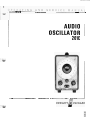
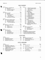
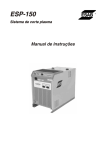
HP Archive
This vintage Hewlett Packard document was preserved
and distributed by
www. hparchive.com
Please visit us on the web !
Thanks to on-line curator: Kenneth Kuhn for supplying and
scanning this vintage document.
..
__ __
.
..
.
I
-
AUDIO
OSCILLATOR
201C
.-
.
I-.
.
CERTIFICATION
The Hewlett-Packard Company certifies that this instrument was
thoroughly tested and inspected and found to meet its published
specifications when it was shipped from the factory. The HewlettPackard Company further certifies that its calibration measurements are traceable to the U.S. National Bureau of Standards to
the extent allowed by the Bureau’s calibration facility.
WARRANTY AND ASSISTANCE
All Hewlett-Packard products are warranted against defects in
materials and workmanship. This warranty applies for one year
from the date of delivery, or, in the case of certain major components listed in the operating manual, for the specified period. We
will repair or replace products which prove to be defective during
the warranty period provided they are returned to HewlettPackard. No other warranty is expressed or implied. We are not
liable for consequential damages.
Service contracts or customer assistance agreements are available
for Hewlett-Packard products that require maintenance and repair on-site.
For any assistance, contact your nearest Hewlett-Packard Sales and
Service Office. Addresses are provided at the back of this manual.
OPERATING A N D SERVICE M A N U A L
-hp- Part No. 201 C-906
MODEL 201C
AUDIO OSCILLATOR
Serials Refixed: 0961 A
Appendix C, Manual Backdating Changes.
adapts this manual to Serials Prefixed:
35146357 and below, 331-, 311-, 308-,
236-, 133-, 006- and serials 1358 to 557
and below.
Copyright Hewlett-Packard Company 1959
P.O. Box 301, Loveland, Colorado, 80537 U.S
Printed: Aug 1971
Model 201C
Table of Contents
TABLE OF CONTENTS
Section
Page
I
GENERAL INFORMATION . . . . . . . . . . . . . . . . 1-1
1-1. Descrintion ........................
1-1
1 4 . Instrument Identification . . . . . . . . . . . . . 1-1
1-7. Accessories Available . . . . . . . . . . . . . . . . . 1-1
Section
Page
I1
INSTALLATION.. ......................
.2-1
2-1. Inspection ........................
.2-1
2 4 . Power Requirements . . . . . . . . . . . . . . . . .2-1
2-6.
Power Cable . . . . . . . . . . . . . . . . . . . . .
.2-1
2-9.
230-Volt Operation . . . . . . . . . . . . . . ..2-1
2-1 1. Repackaging for Shipment . . . . . . . . . . . . .2-1
Section
Page
111 OPERATING INSTRUCTIONS . . . . . . . . . . . . . .3-1
3-1. Controls and Terminals . . . . . . . . . . . . . . .3-1
3-7. Operating Instructions . . . . . . . . . . . . . . ..3-1
3-8.
Low Level Applications . . . . . . . . . . . . .3-1
Section
Page
IV
THEORY OF OPERATION
.4-1
4-1. General . . . . . . . . . . . . . . . . . . . . . . . . . .4-1
4-3. Oscillator Section . . . . . . . . . . . . . . . . . . .4-1
4-8. Amplifier Section . . . . . . . . . . . . . . . . . . .4-1
Page
Section
V
MAINTENANCE . . . . . . . . . . . . . . . . . . . . . . . .5-1
5-1. Introduction . . . . . . . . . . . . . . . . . . . . . .5-1
5-3. Test Equipment . . . . . . . . . . . . . . . . . . . . .5-1
5-5. Periodic Maintenance . . . . . . . . . . . . . . . . . 5-1
5-8. Performance Checks . . . . . . . . . . . . . . . . . 5 - 1
Section
Page
5-10. Calibration Accuracy Check . . . . . . . . . 5-1
5-11 .
Frequency Response Check . . . . . . . . .. 5 - 1
5-12,
Output Check . . . . . . . . . . . . . . . . . . . .5-2
5-13.
Distortion Check . . . . . . . . . . . . . . . . . .5-2
5-16. Adjustments . . . . . . .
5 -3
5-17.
Power Supply . . . .
5-3
5-19.
Output Voltage
5-3
5-20.
Distortion Adjns
5 -3
5-21.
Frequency Calihra ion
5-3
5-22.
Dial Retracking
........ . 5 4
5-24. Troubleshooting . . . . . . . . . . . . . . . . . . . . 5 4
5-25.
Trouble Localization . . . . . . . . . . . . . . . 5 4
5-28. Troubleshooting Chart . . . . . . . . . . . . . . 5 4
5-30.
Excessive Distortion . . , .
5-32. Repair . .
5-33. Cabinet
5-35.
TubeRe
. . . . . . . . . . . . . . . . .5-8
5-37.
Replacement of Lamp . . . . . . . . . . . . . .5-8
5-39.
Replacing Range Switch . . . . . . . . . . . , 5 4 3
540. Adjustment of Factory Selected
Components
5-8
Section
Page
VI
REPLACEABLE PARTS . . . . . . . . . . . . . . . . . . .6-1
6-1. Introduction ......................
.6-1
6-4. Ordering Information . . .
6-1
6-6. Non-Listed Parts
6-1
APPENDICES
A. CODE LIST OF MANUFACTURERS
B. SALES AND SERVICE OFFICES
C. MANUAL BACKDATING CHANGES
LIST OF TABLES
Number
Page
1-1. Specifications . . . . . . . . . . . . . . . . . . . . . . . . . . .
I0
5-1. Required Test Equipment . . . . . . . . . . . . . . . . . . 5 0
5-2. Tube Replacement List . . . . . . . . . . . . . . . . . . . . 5 0
5-3. Calibration Accuracy Check . . . . . . . . . . . . . . . .5-1
Number
Page
54. Frequency Response Check . . . . . . . . . . . . . . . . .5-2
5-5.
5-6.
6-1.
Troubleshooting Chart. . . . . . . . . . . . . . . . . . . . . 5 - 5
Factory Selected Components . . . . . . . . . . . . . . . 5 - 8
Replaceable Parts ........................
.6-2
LIST OF ILLUSTRATIONS
Number
Paae
1.1. Model 201C . . . . . . . . . . . . . . . . . . . . . . . . . . . . .
1-1
4-1. Block Diagram of Model 201C . . . . . . . . . . . . . . . 4 0
4-2. Simplified Schematic Diagram of
Oscillator Section . . . . . . . . . . . . . . . . . . . . . . .4-1
4-3. Oscillator Network Characteristics . . . . . . . . . . . .4-1
5-1. Calibration Accuracy Check . . . . . . . . . . . . . . . .5-1
5-2. Frequency Response and
Output Check .........................
.5-2
........................
Page
.5-2
54,
Left Side View. . . . . . . . . . . . . . . . . . . . . . . . . .
.5-6
5-5.
5.6,
Bottom and Right Side View . . . . . . . . . . . . . . . .5-7
Number
5-3. Distortion Check
5-7.
Tube Location, Voltage
and Resistance .....................
.5-9/5-10
Schematic Diagram . . . . . . . . . . . . . . . . . . .5-9/5-10
iii
Section I
Model 201C
Table 1-1. Specifications
Frequency Range: 20 Hz to 20 kHz in three ranges.
Ranges
x1
x10
XlOO
20 Hz to 200 Hz
200 Hz to 2 kHz
2 kHz to 20 kHz
Calibration Accuracy: *I%. Calibration
provided for standardizing bands.
controls
Frequency Stability: *2% under normal temperature
conditions and including initial warmup, aging of
components etc.
Dial: 6-inch diameter, calibrated over 3OOo of arc.
Total scale length SO inches.
Frequency Response: +1 dB over entire frequency range
(Reference 1 kHz.)
Output: 3 watts maximum or 42.5 volts into 600-ohm
load. One terminal at ground potential. SO volts
maximum no-load voltage.
Distortion: Less than 1/2%, 50 Hz to 20 kHz at 1 watt
output. Less than I%, 20 Hz to 20 kHz at 3 watts
output.
Attenuator: 0 to 4OdB in 10 dB steps-concentric
amplitude control varies output continuously zero
to maximum at any attenuator setting.
Output Impedance:
600 ohms ?lo%,20 dB, 30 dB and 40 dB settings
Less than 600 ohms, 0 dB and 10 dB settings.
Hum Voltage: Less than 0.03% of rated or attenuated
output. (Amplitude control at maximum.)
Power: 115/230 volts f l o % , 48/440 Hz
nominal. 120 W maximum.
85 W
Accessories Available:
HP llOOOA Cable Assembly, 4 feet of RC-SS/U
SO-ohm coaxial cable terminated at each end with a
dud banana plug.
HP llOOlA Cable Assembly, 45 inches of RC-SS/U
SO-ohm coaxial cable terminated at one end with a
dual banana plug and with a UGSS/U Type BNC male
connector at the other.
Dimensions:
Cabinet Mount: 7-1/2 inches wide, 11-1/2 inches high,
12-1/2inches deep.(l91 X 2 9 2 X 3 1 8 m m ) .
Rack Mount: 19 inches wide, 6-31/32 inches high,
10-5/16 inches deep (482,6 X 177,O X 261,9 mm).
Weight:
Cabinet Mount: Net, 16 Ibs. (7,2 kg);Shipping, 19 Ibs.
( 8 6 kg).
Rack Mount:
Net, 20 Ibs. (9 kg);Shipping, 30 Ibs. (13.5 kg)
e
Section I
Model 201C
SECTION I
GENERAL I N F O R M A T I O N
1-1. OESCRIF'TION.
1-2. The Model 201C Audio Oscillator (Figure 1-l), has
been designed for a general purpose, audio testing and
measurements such as amplifier testing, transmission line
mcasurements, loud-speaker testing, frequency comparison,
and other high fidelity tests. It contains a built-in stabilized
amplifier stage delivering 3 watts of power into a 600uhm
resistive load with distortion held to 112 per cent at
frequencies above 50 Hz at 1 watt output and less than 1
per cent from 20 Hz to 20 kHz at 3 watts output.
9
1-3. The output level of thc Model 201C is adjustable. An
attenuator is also provided to adjust the output level over a
0 to 40 dB range in 10 dB steps. The attenuator is a
bridged-T type providing virtually a 600uhm impedance
looking back into the instrument (at attenuation levels of
20 dB and above), and keeps the hum level low relative to
small signal levels. With thc attenuator in the 0 dB position,
output impcdance becomes less than 600 ohms, thus
insuring good voltage regulation for varying load conditions
providmg maximum output power.
1-4. INSTRUMENT IDENTIFICATION.
1-5. Hewlett-Packard uses a two-section serial number. The
first section (prefix) identifies a series of instruments. The
last section (suffm)identifies a particular instruiuent within
the series. If a letter i s included with the serial number, it
identifies the country in which the instrument was manufactured.
1-6. If the serial prefix of your instrument dirfers from the
one on the title page of this manual, a change sheet will he
supplied to make this inanual cornpatable with newer
instruments or the backdating information in Appendix C
will adapt this inanual to earlier instruments. AU correspondence with Hewlett-Packard should include the complete
serial number.
1-7. ACCESSORIES AVAILABLE.
1-8. 1 IOOOA Cable Assembly. This cable assembly consists
of two dual banana plugs and a section of RC-SSCjU
5 0 u h m coaxial cable, 44 inches overall. Plugs are for
binding posts spaced 314 inch between centers.
1-9. IlOOlA Cable Assembly. This cable assembly consists
of a dual banana plug, a UG-88/U Type BNC male
connector and a section of RC-SSC/U 50uhm coaxial
cable, 45 inches overall. The dual banana plug is for binding
posts spaced 314 inch between centers.
Figure 1-1. Model 201C
1-1
Section 11
Model 201C
SECTION II
INSTALLATION
2-1. INSPECTION.
b. Connect a new jumper between terminal 3 and 4.
2-2. Unpack the instrument upon receipt and inspect it for
signs of physical damage such as scratched panel surfaccs,
broken knobs, etc. If there is any apparent damage, fde a
claim with the carrier and refer to the warranty page in this
manual.
c. Change the line fuse to a 0.8 A slo-blo.
2-3. An electrical inspection should be performcd as soon
as possible after receipt. To aid in electrical inspection a list
of performance checks are in Section V, Paragraph 5-8.
These procedures make a good test as part of incoming
qualitycontrol inspection.
2-4. POWER REQUIREMENTS.
2-8. The Model 201 C requires a power source of 118/230
volts + 10 76, 48 t o 440 Hz, which can deliver up to 120
waits.
2-6. POWER CABLE.
2-1. For the protection of operating personnel, the
National Electrical Manufacturers’ Association (NEMA)
recommends that the instrument panel and cabinet be
grounded. This instrument is equipped with a three-prong
conductor power cablc which, when plugged into an
appropriate receptacle, grounds the instrument. The offset
pin on the power cable three-prong connector is the ground
pin.
2-8. To preserve the protection feature when operating the
instrument from a twocontact outlet, use a three-prong to
two-prong adapter and connect the pigtail on the adapter to
ground.
2-9. 230-VOLT OPERATION.
2-10. To operate the Model 201C from a 230-volt *IO%
source, change the primary windings of T2 from a parallel
to a series arrangement. Refer to the schematic diagram and
proceed as follows:
a. Remove the two bare wire jumpen from the
terminals on T2. These jumpers connect terminal 2
to 3 and 4 to 5 on the primary winding.
2-11. REPACKAGING FOR SHIPMENT,
2-12. The following is a general guide for repackaging for
shipment. If you have any question, contact your local -hpSales and
office.(seeAppendlx at the back ofthis
manual for office location,)
NOTE
If the instrument is to be shipped to
HewlettPackard for service or repair,
attach a tag to the instrument identifying
the owner and indicating the service or
repair t o be accomplished; include the
model number and full serial number of
the instrument. In any correspondence,
identify the instrument by model
number, serial number and serial number
prefix.
a. Place instrument in original container if available.
If original container is not available, a suitable onc
can be purchased from your nearest h p - Sales and
Service Office.
If original container is not used,
b. Wrap instrument in heavy paper or plastic before
placing in an inner container.
c. Use plenty of packing material around all sides of
instrument and protect panel faces with cardboard
strips.
d. Place instrument and inner container in a heavy
carton or wooden box and seal with strong tape or
metal bands.
e. Mark shipping container with
INSTRUMENT,” “FRAGILE etc.
“DELICATE
2-1
Section 111
Model 201C
SECTION 111
OPERATING INSTRUCTIONS
3-1. CONTROLS AND TERMINALS.
3-2. ON. Toggle switch controls line voltage to instrument.
3-3. RANGE. Three-position rotary switch selects various
values of resistance in the bridge circuit of the RC
oscillator. The position of this switch indicates the
multiplying factor for the frequency dial calibration.
3 4 . FREQUENCY dial. This control varies the capacitance
in the bridge circuit of the RC oscillator to vary output
frequency between range switch steps. The dial is calibrated
from 20 to 200 and its indication multiplied by the factor
indicated by the RANGE switch will give the actual output
frequency of the oscillator. The small knob below the
frequency dial is a vernier control for thc dial.
3-5. ATTENUATION. This is a dual concentric control.
The inner control is a potentiometer which adjusts the
amplitude of the oscillator voltage admitted to the
amplifier, and therefore, it adjusts the output voltage of the
instrument from zero to a maximum value established by
the attenuator. The outer control is a bridged-T type
attenuator providing 0 to 40 dB of attenuation in 10 dB
steps.
3-6. OUTPUT terminal. Two binding posts on the lower
center of the front panel are the output terminals for the
oscillator. Terminal marked G is connected to the chassis of
the instrument.
3-7. OPERATING INSTRUCTIONS.
a. Connect the power cable to required power source.
b. Turn the power switch ON and allow approximately
five minutes for the instrument to reach its normal
operating temperature.
c. Set the FREQUENCY dial and RANGE switch for
desired output frequency.
d. Set ATTENUATION outer control to 0 dB, then set
inner control (amplitude) for desired output
voltage.
e. Set ATTENUATION outer control, if desired, to
reduce output level in 10 dB steps.
NOTE
When the attenuator is in the OdB
position the amplifier output is delivered
from less than 600 ohms at frequencies
below 5000Hz, and it will produce its
rated output (3 watts) across a load of
600 ohms. When the attenuator is
positioned
for
20 dB or more
attenuation, the internal impedance is
600 ohms.
3-8. LOW LEVEL APPLICATIONS.
3-9. To avoid excessive noise and hum at low output levels
( 4 0 dBm or less), it it good practice to attenuate the
oscillator output -30 or 4 0 dB and use the amplitude
control as an output vernier to obtain desired level.
3-1
Section IV
Model 201C
ATTENUATOR
ATTENUATION
Q
VERNIER
I
ATTENUATION]
I
I
I
I
I
OSCILLATOR
VI 8. v2
POWER
SUPPLY
AMPLIFIER
v3, v4, v5
t-
0-40db
ATTENUATOR
600n 0 - l O d b
600n 2 0 - 4 0 d b
I
-201C
Figure 4-1. Block Diagram of Model 201C
8 1988
Section IV
Model 201C
SECTION IV
THEORY O F OPERATION
4-1. GENERAL.
4-2. The Model 201C consists of an oscillator section, an
amplifier section, an output attenuator and a power supply
as shown in the block diagam, Figure 4.1.
BO
04
4-3. OSCILLATOR SECTION.
4 4 . The oscillator section consists of V1 and V2 as a
resistance coupled amplifier containing two feedback loops.
The positive feedback loop sets up oscillation while the
negative feedback loop reduces distortion and maintains a
constant amplitude of oscillation. The positive feedback
network contains fixed resistances (established by the
RANGE switch) and a variable capacitance. A simplified
schematic diagam is shown in Figure 4-2. The network is
designedsothat R l , C l A a n d B = R 8 , C l C a n d D .
I
I
I
T
FREQUENCY
Figure 4-3. Oscillator Network Characteristics
I
Figure 4-2. Simplified Schematic Diagram of
Oscillator Section
4-5. The oscillator output is coupled to the input stage
through C8, and the input voltage is derived from this
signal. Oscillation will occur when there is zero phase shift
between the voltage applied to the network and the voltage
applied to the grid of V1. The zero phase shift point is also
the point of minimum loss through the network as shown
in Figure 4-3. The frequency of oscillation (relative
frequency in Figure 4-3) is given by the expression:
1
Fr = 2 n d (R1 . ClA,B) (R8.ClC,D)
-
4-6. The cathode by-pass capacitors in the oscillator
section C5, C7 correct phase shift at higher frequencies.
4-7. The negative feedback network minimizes change of
output amplitude with change in frequency. The
incandescent lamp, used as a cathode bias resistor for V1, is
part of the negative feedback voltage divider. It has a
temperature resistance characteristic such that its resistance
increases in direct proportion to the voltage applied t o it.
Thus, changes in its resistance will change the amount of
negative feedback in the oscillator output. The thermal
inertia of the lamp is great enough to be unaffected by sine
wave voltages at the lowest frequencies involved.
4-8.AMPLIFIER SECTION.
4-9. The amplifier section of the instrument consists of a
voltage amplifier V3A direct coupled to a phase inverter
V3B, and a push-pull output stage V4 and VS. The output
transformer contains a tertiary winding for overall negative
feedback around the amplifier. As a result of negative
feedback in excess of 30 dB, very little distortion is
introduced by the amplifier section of the instrument.
4-1
Model 201C
Section V
Table 5-1. Recommended Test Equipment
Model
Required Characteristics
Instrument Type
Multi-Function
Meter
DC Voltage Range: 1 to 310 volts
Ohmmeter Range: 1 ohm to 500 megohms
Accuracy: 53%
AC Voltage Ranee: 1 m v to 100 volts
-hp- Model 421A
Distortion
Analyzer
Distortion Measurement
Range: 20 Hz to 20 kHz
-hp- Model 33 1A
Frequency Calibration
Accuracy : +2%
Elimination Characteristics:
Fundamental frequency reduced by
more than 60 dB
Sensitivity: Ability to measure distortion
levels of 1% full scale
I
Frequency Range: 20 Hz to 20 kHz
Electronic
Counter
TUBE
TYPE
FUNCTION
Oscillator
Oscillator
V6
I
- h p Model 5223L
CHECK REQUIRED
I
Table 5-5, step 2
6SNlGT
Voltage Amp.
phase inverter
Table 5-5, step 3
6V6GT
6V6GT
Output Tubc
Output Tube
Table 5-5, step 3
5AR4
Rectifier
Table 5 - 5 , step 1
I
Section V
Model 201C
SECTION V
MAINTENANCE
5-1. INTRODUCTION.
5-10. CALIBRATION ACCURACY CHECK.
a. Connect test setup as shown in Figure 5-1
5-2. This section provides maintenance and service
information for the Model 201C Audio Oscillator. The
section includes recommended test equipment, a tube
replacement table, performance checks, adjustments, repair
procedures and a troubleshooting table. The performance
checks will verify proper iiistrument operation.
5-3. TEST EQUIPMENT.
b. Check the period or frequency for each frequency
setting shown in Table 5-3.
hp
ZOIC
AUDIO
OSCILLATOR
5 4 . Test equipment recommended for use in maintaining
and checking performance of the Model 201C is listed in
Table 5-1. Equipment having similar characteristics can be
substituted for the equipment listed.
5-5. PERIODIC MAINTENANCE.
5 4 . The tuning capacitor drive bearing should be
lubricated once or twice a year depending upon the amount
of use. One drop of light machine oil in each of the bearing
holes is adequate. The holes are located in the hearing
projections of the vertical casting behind the front panel.
Figure 5-1. Calibration Accuracy Check
Table 5-3. Calibration Accuracy Check
5-1. The inside of the instrument should be cleaned
occasionally to prevent accumulation of dust and dirt from
shorting plates of the main tuning capacitor.
Clean tuning capacitor with extreme care.
DO NOT apply any force to it which
could beud the plates and destroy
calibration. Compressed air under a
pressure not to exceed 60 psi is
recommended for cleaning.
x1
20
XI0
200
20
XI00
200
20
so
so
SO
200
period: 49.5 to 50.5 ms
period: 19.9 to 20.1 ins
period: 4.95 to 5.05 ms
period: 4.95 to 5.05 ins
freq: 495 to 505 Mz
freq: 1980 to 2020 Hr
freq: 1980 to 2020 Hr
freq: 4950 to 5050 Hr
frcq: 19800 to 20200 Hz
5-11. FREQUENCY RESPONSE CHECK.
5-8. PERFORMANCE CHECKS.
5-9. The Performance Checks are front panel procedures
designed to compare the Model 201C with its published
specifications. These checks may be incorporated in
periodic maintenance, post repair, and incoming inspection.
The Performance Checks should be conducted before any
attempt is made to adjust or calibrate the instrument. A
Performance Check Test Card is provided at the end of this
section for recording the performance of the instrument.
The card may be removed from the manual and used as a
permanent record of the incoming inspection or of a
routine Performance Check.
a. Connect test setup as shown in Figure 5-2,
including a 600 ohm load resistor across the
output terminals of the Model 201C.
b. Set the Model 201C frequency to 1 kHz and
Attenuation Switch to 0 dB.
c. Adjust the Model 201C amplitude vernier to
obtain 0 dB reading on the voltmeter.
d. Set the Model 201C to each of the frequency
settings in Table S 4 . At each setting the voltmeter
should read 0 dB i-1 dB.
5-1
Section V
Model 201C
b. Set Model 331A controls as follows:
h p ZOIC
INPUT . . . . . . . . . . . . . . . . . . . . . . . AF
FREQUENCYRANGE . . . . . . . . . . . . . . X1
FREQUENCY dial . . . . . . . . . . . . . . . . 5 0
FUNCTION . . . . . . . . . . . . . VOLTMETER
METER RANGE . . . . . . . . . 3 0 RMS VOLTS
AUDIO
OSCILLATOR
VOLTMETER
c. On Model 201C set RANGE t o X1 and frequenvy
dial to 50 (SO Hz).
Figure 5-2. Frequency Response and Output Check
e. On Model 331A set FUNCTION to SET LEVEL,
METER RANGE to loo%, and adjust INPUT
SENSITIVITY for 100% (full scale is 100%).
Table 5 4 . Frequency Response Check
Range
Dial Setting
Tolcrance
~~
x10
20
200
20
200
20
200
x1
XlOO
-1 dB to +I
-1 dB to +I
-1 dB t o +I
-1 dB to +I
-1 dB to +I
-1 dB t o +I
dB
dB
dB
dB
dB
dB
5-12. OUTPUT CHECK.
a. Connect test setup as shown in Figure 5-2, using a
600 ohm 3 watt load resistor.
b. Set the Model 201C Attenuation switch to 0 dB.
c. Increase attenuation vernier in CW direction until
the voltmeter reads 42.5 volts. This is an output of
3 watts.
5-13. OlSTORTlON CHECK.
5-14. One-Watt Output.
a. Connect test setup as shown in Figure 5-3,
including a 6004hm load resistor across the
output terminals of Model 201C.
I
d. Adjust output voltage levcl of Model 201C, with
vernier, to obtain 24.5 volts on Model 331A.
f. Set FUNCTION to DISTORTION and tune Model
331A for null.
g. Set METER RANGE to 1% and retune for null.
Reading should be less than 1/2% (full scalc is 1%).
h. Repeat steps a through g, except set Model 201C
RANGE to XlOO and frequency dial to 200
(20 kHz) and Model 331A FREQUE,NCY RANGE
to XIK and FREQUENCY dial to 20.
5-15. Three-Watt Output.
a. Connect test setup as shown in Figure 5-3,
including a 600 ohm 3 watt load resistor across the
output terminals of Model 201C.
b. Set Model 331A controls as follows:
INPUT . . . . . . . . . . . . . . . . . . . . . .
.AF
FREQUENCY RANGE . . . . . . . . . . . . . .XI
FREOUENCYdial . . . . . . . . . . . . . . . . 20
FUNCTION . . . . . . . . . . . . . . . . .METER
METER RANGE . . . . . . . . 100 RMS VOLTS
~~
c . 00 Model 201C set RANGE to X1 and frequency
dial to 20 (20 Hz).
d. Adjust output voltage level of Model 201C, w t h
vernier,to obtain42.5 volts onModel331A.
hp201C
AUDIO
OSCILLATOR
e. On Model 331A set FUNCTION to SET LEVEL,
METER RANGE to loo%, and adjust INPUT
SENSITIVITY for 100%(full scale is 100%).
f. Set FUNCTION t o DISTORTION and tune Model
331A for null.
g. Set METER RANGE t o 1% and retune for null.
Reading should be less than 1% (full scale is 1%).
Figure 5-3. Distortion Check
5-2
h. Repeat steps a through g, except set Model 201C
RANGE t o XlOO and frequency dial to 200
Model 201C
Section V
(20 kHz) and Model 331A FREQUENCY RANGE
t o X1K and FREQUENCY dial to 20.
b. Set the RANGE switch to XI0 and the dial to 20.
Connect the instrument to the Frequency
Counter.
NOTE
c. If the output from the Model 201C is not 200 Hz
adjust R7A so that the output is exactly 200 Hz
when the dial rests on 20 (X10range).
If the Model 201C iy slightly out of
specification, refer to “Adjustments”
Paragaph 5-16 and “Factory Selected
Components” Table 5 6 . If a malfunction
exists refer t o “Troubleshooting” Paragraph 5-24.
5-16. ADJUSTMENTS.
5-17. POWER SUPPLY.
5-18. Proper operation of the power supply is vital to
proper operation of the instrument. Excessive ripple in the
output or a low output voltage can cause the instrument t o
have excessive distortion or otherwise operate out of
specification. To check the power supply, measure the
power supply ripple and check the Bt voltage as described
in Table 5-5 (1). For cabinet removal refer to Paragraph
5-33.
5-19, OUTPUT VOLTAGE.
a. Connect Model 201C as shown in Figure 5-2 and
proceed as follows:
b. Rotate RANGE switch to XI0 position
NOTE
It is necessary to remove the instrument
from the cabinet for each adjustment,
and then replace it for check after each
adjustment. The instrument oscillates at a
different frequency whcn removed from
the cabinet. Use non-metallic (bakelite,
etc.) aligning tools to adjust trimmer
capacitors
d. Set the Model 201C output to any convenient
level for reference. Change the dial setting to 200
and note the output. The level should remain at
the established reference, and frequency should be
within 1-112 percent of 2000 Hz. If this is not the
case, adjust CZ and C4 alternately to obtain
2000 Hz at the established reference level.
e. Check dial tracking across the XI0 range. In nearly
all cases the dial tracking should be satisfactory. If,
however, the dial is out of calibration in the same
direction across the band, the dial may be adjusted
slightly relative to the tuning unit as follows:
c. Rotate frequency dial to 20.
1. Remove center knob on frequency dial
d. Rotate amplitude control to 100 (fully clockwise).
e. Set ATTENUATION switch to 0 dB position.
2. Loosen four screws which secure dial plate to
drive shaft.
f. Adjust RlO for 4 5 volt indication on the voltmeter.
3 . Reset dial by desired amount.
5-20. DISTORTION ADJUSTMENT.
4. Tighten four securing screws. Replace center
knob.
a. Connect the 201C output to the input of the
331A Distortion Analyzer as in Figure 5-3.
5 . Repeat steps b through d of Paragraph 5-21.
b. Set the 201C frequency dial to 50 and the Range
t o x1
f. If the dial tracking cannot be brought into
specifications in this manner, or by compromising
the calibration at the band extremes slightly
(within specifications) to accommodate a larger
error in the middle of the band, then a retracking
of the dial and the main tuning capacitor is
indicated. Retracking the dial involves bending the
split rotor plates on the main tuning capacitor C1.
Assuming dial retracking is unnecessary, proceed
with steps g and h.
c. Set the attenuation controls for a 42.5 volt output
into a 600 ohm load.
d. Adjust R48 for minimum distortion as indicated
by the331A.
5-21. FREQUENCY CALIBRATION.
a. Turn on the oscillator and allow 30 minutes for it
to warm up. Put 600 ohm resistive load on
oscillator for all adjustments.
g. Place RANGE switch in the XI00 position, and
turn the frequency dial to 20. Adjust R6A so that
the instrument oscillates at 2 k k .
5-3
Model 201C
Section V
h. Place RANGE switch in the X1 position, and set
the frequency dial t o 20. Adjust R8A so that
instrument oscillates at 20 Hz.
5-22. DIAL RETRACKING.
5-23. Dial tracking is performed on the X10 range
a. Check frequencies at 200, 150, 100, 70, 50, 30,
and 20 on the dial.
b. For each point outside specifications, bend split
rotor plates (these plates are the outside plates of
each section of C1) as described below to bring
point on dial into calibration.
NOTE
Outside rotor plates of each section are
divided into segments. The segment
associated with specific dial points are
those which engage the stator when the
desired dial point is uqder the index. To
raise. the frequency spread the plates. To
lower frequency squeeze plates.
c. Start bending at highest frequency out of
calibration, and work toward the lowest
frequency. Bend the plates of the front two
sections by the same amount as the rear two
sections. It should not be necessary t o bend plates
near the high end of the dial.
d. If the above procedures do not result in correct
calibration, start over by adjusting C2 and C4.
Then work toward the low end by setting the dial
to the next numbered point and bending one of
the outer rotor plates in each section 3f C1 at the
point of mesh. Continue this procedure t o the low
end of the dial to obtain approximately corrtct
frequencies. Repeat the bending procedure from
the high end, this time making fine adjustments of
frequency with the other outer rotor plates. In this
way, bending of any one plate is minimized.
e. If bending process moves the dial out of
calibration at ‘?A”, restore calibration at this
point by bending the plates rather than by an
adjustment of R7A.
NOTE
If the XI0 range is within specifications,
and the high end of the X1 or XI 00 range
is out of specifications, refer to “Factory
Selected Components”, Table 5-6.
5-24. TROUBLESHOOTING.
5-25. TROUBLE LOCALIZATION.
5-26. If the instrument fails to operate, check the power
source, power cord, and fuse before attempting more
5-4
complicated troubleshooting. If the instrument operates,
but not satisfactorily, check the test setup for correct
voltages, connections, terminations, etc.
5-27. The conservative design of the Model 201C indicates
that most normal aging effects will be remedied by tube
replacement and subsequent adjustments. Electrical
troubleshooting should always be preceded by a visual
inspection. A cold tube found simply by touch may save
considerable time and effort in restoring the instrument to
operation. Look for signs of damage and overheated or
burned-out components associated with certain types of
tube failure; be alert for looseness of parts which, if not
trouble sources themselves, suggest areas of future trouble.
The Troubleshooting Chart, Table 5-5, lists checks to be
performed starting with the power supply and proceeding
through the instrument in a manner which isolates circuit
failures and also includes possible causes and remedies.
Isolation of a circuit failure is often possible by simply
operating the front pane1 controls and observing their
effect.
5-28. TROUBLESHOOTING CHART.
5-29. For simplification in the following chart, tubes
usually have been referenced, but remember that
components associated with reference tubes are also failure
possibilities. Perform the steps in the chart in the order
given since the chart assumes that the section ahead of the
one under investigation is operating satisfactorily. For all
testing of the Model 201C the use of a variable transformer
to adjust the line voltage to +lo%of the normal line voltage
is recommended. An instrument in good condition should
operate over this range. An instrument with marginal
operation (from weak tubes, etc.) can be quickly identified
at low line voltages, and such weaknesses become easier t o
trace.
5-30. EXCESSIVE OISTORTION.
5-31. In general, distortion in the Model 201C can come
from the following:
a. Leaky coupling capacitors, C6, C8, C9, C10, C11.
There should be no dc voltage on grids following
these capacitors.
b. Defective electrolytic fdter and decoupling capacitors. Make ripple measurements as described in
Table 5-5.
c. Defective tubes. When a tube is replaced in the
instrument, the distortion measurement should be
rechecked.
d. Low B+. Check the supply voltages against those
shown in the Voltage and Resistance diagram with
a line voltage of 115 volts.
5-32. REPAIR.
&
Model 201C
Section V
Table 5-5. Troubleshootinr Chart
CHECK OR SYMPTOM
POSSIBLE CAUSE
REMEDY
1. POWER SUPPLY
Measure +310 VDC (at 115 Vline) between pin 8,
V6 and chassis.
Voltage low
Defective V6
Replace
Defective fdter
capacitor C12B or C
Replace
Defective V6
Replace
Defective C12A
Replace
Defective V1 or V2
Replace.
Defective lamp R T l l
Replace lamp (See Paragraph
5-37).
R10 out of adjustment.
Defective V1 or V2.
Adjust R10 for proper
oscillator voltage or
replace V1 or V2.
Dirty contacts on
RANGE switch
Check and clean RANGE
switch. Replace assembly
when resistors are open
or damaged. See Paragraph 5-39.
Shorted C1, C2, C3,
or c4.
Replace defective trim.
mers (C2, C3, or C4).
Foreign material may
short C1.
Defective lamp R T l l
(Notch will appear
in oscillator output
waveform viewed on
oscilloscope .)
Replace lamp (See Paragraph
5-37).
Defective VI or V2
Defective lamp, R T l l
Replace (See Paragraph 5-35).
Replace lamp.
Measure power supply ripple at pin 4 of V4 or VS.
Ripple in excess of .25 vac.
Measure ripple at junction R28 and C12A.
Ripple in excess of 0.01 vac.
2. OSCILLATOR
Measure oscillator hum between negative terminal
of C8 and chassis. Remove lamp RT11 to eliminate
oscillator signal.
Hum in excess of 0.02 vac
Replace lamp and measure oscillator voltage between negative terminal of C8 and chassis (see
Figure 5-5).
Oscillator voltage not within range indicated on
schematic.
Excessively high OSC voltage
Measure distortion between negative terminal of
C8 and chassis.
If it exceeds .5% at 1 watt and 1000 Hz
5-5
Model 201C
Section V
Table 5-5. Troubleshooting Chart (Cont’d)
POSSIBLE CAUSE
CHECK OR SYMPTOM
REMEDY
3. AMPLIFIER
Load instrument with 600 ohms. Measure low
frequency distortion at output terminals.
Defective V4 or VS
Replace
Weak signals driving V4 and V5
Defective V3
Replace
Amplitudes of signals driving V4 and V5
not equal.
Defective R21
or R22
Investigate and replace
Measure dc voltage for approximately 0.2 volts.
Voltage high.
Defective C9
Replace (See Paragraph 5-31).
Voltage above satisfactory. Control still produces unstable output variation.
Defective R17
Replace
Excessive 2nd Harmonic distortion.
Load instrument with 600 ohms. Measure signal
voltage on V3A grid (pin 5) for approximately
13 V rms when instrument delivers 1 watt. Signal
voltage on grids (pin 5) of V4 and V5 should be
approximately 5 V rms.
Rotation of amplitude control causes erratic
amplitude variation in output.
v4
v3
v5
V6
52
R25
Cll
s;
Ri7
d9
TI
Figure 5 4 . Left Side View
T2
c12
Section V
Model 201 C
RIO
R26 C 5
C6
R13
R33
CID
\
R14
C7
R23
RZI
54
I
Figure 5-5. Bottom and Right Side Views
SI
RZ9
Model 201C
Section V
5-33. CABINET REMOVAL.
limits specified on the schematic, adjust R10 to obtain
proper oscillator voltage.
5-34. To remove instrument from the cabinet, unscrew the
two machine screws on the rear of cabinet and pull front
panel forward. The bezel remains attached to front panel.
5-39. REPLACING RANGE SWITCH.
a. Remove instrument case (see Paragraph 5-33)
b. Remove defective RANGE switch. Note routing of
leads.
5-35. TUBE REPLACEMENT.
5-36. Tubes used in t h e Model 201C are listed in the Tube
Replacement List (Table 5-2). A tube may be replaced with
any tube of its type having standard characteristics, but
distortion measurements should be made after replacing
any tube, with the exception of the rectifier tube, t o insure
that the instrument still meets the specifications set forth in
the front of this manual.
c. Install replacement switch with black wire toward
the center shield of the chassis and the wiper lugs
on the ceramic wafer horizontal.
d. Carry out frequency calibration procedure as
described in Paragraph 5-21.
5-37. REPLACEMENT O F LAMP, RTl1.
5-40. A D J U S T M E N T
COMPONENTS.
5-38. The lamp operates well below its rating and should
have a long life, unless it is damaged by severe mechanical
vibration. A damaged lamp may be detected by the
presence of a notch in the output waveform, and by the
presence of excessive oscillator voltage. If the lamp opens,
the circuit will not oscillate. When the lamp is replaced,
check the oscillator voltage between the negative terminal
of C8 and the chassis. If the voltage does not fall within the
541. Certain components within the Model 201C are
individually selected in order t o compensate for slightly
varying circuit parameters. These components are denoted
by an asterisk (*) on the schematic, and the typical value is
shown. Table 56 describes the function of the factory
selected components and gives instructions for their
selection. Normally, these components do not need to be
changed unless another associated component is changed.
OF
FACTORY
SELECTED
Table 5 4 . Factory Selected Components
COMPONENT
FUNCTION AND SELECTION
MIN.
AVERAGE
MAX.
27 pF
56 pF
68 pF
C5*
Compensates for High Frequency response
Decrease C to increase amplitude (X100 range).
C13* and R30*
Minimizes distortion at 20 kHz
Change size of R30 first. C13 has very little
effect. Value of R30 is function of
oscillator tubes.
10 kohm
12 kohm
16 kohm
C14*
Adjusts frequency at high end of XI0 range.
0
0
1.5 pF
C15*
Adjusts frequency at high end of X1 range.
0
1 PF
50 pF
C17*
Decreases distortion caused by oscillations
in the output amplifier.
RY *
Provides proper range for R10 Output Voltage
Adjustment. Increase RY t o increase amplitude.
R14*
Adjusts bias level of V2.
680 ohms
R20*
Changes loop gain of amplifier.
270 kohms
5-8
560 pF
47 pF
1800 ohms
2200 ohms
2600 ohms
V6
v5
v3
V4
5AR4
6V6
6SN7
6V6
470K
85
a
NOTES
1. CONDITIONS O F MEASUREMENT
A L L VOLTAGES AND
RESISTANCES MEASURED FROM
POINTS SHOWN TU CHASSIS
WITH 122 MEGOHM INPUT
IMPEDANCE VTVM.
15
14
!
I
LINEVOLTACE: 115VI60 H z
2. CONTROL SETTINGS
r--E
FREQ. DIAL . . . . . . . . . . . . . . ,100
RANGE . . . . . . . . . . . . . . . . . . XI0
AMPLITUDE . . . . . . . . . . . . .MAX.
500
0
15K
VI
14
680
V2
6AQ5
Figure 5-6. Tube Location, Voltage and Resistance
18
I--*
R3A
RIO
,R3
83K
IX100/
AMPLITUDE
FREQ
RESPONSE
FREQUENCY
DIAL
3
*
v n i w SELLCII'LI DURiNC
MANUIACTLRE
PANEL CONTKOL
5.
PAUEJ. MAKKTNC
7
8
COPYRIGHT
1955 B Y
H E W L E T T -PACKARD
COMPANY
Model
R28
4700
T
T
CIO
01
.
iz20v
RI
2
c9
0.047
R30*
2
C13
-
.
IM
t5"
4
R23
470K
8
3
6
VERNIER
R42
56K
v3
6SN7GT
CII
15K
1.7"
RTII
low
LAMP
c12c
128
0
Model 201C
Section V
+325v
CI5V
4
R34
59480
R35
18370
R36
5400
R37
1297
I
t325V
S3A
ATTENUATION
C12Cl
t350V
5AR4GT
R29
v3
v2
3
3
7
VS
2
DSI
2
Figure 5-7. Schematic Diagram
Page 5-9/5-10
Model 201C
Appendix C
MANUAL BACKDATING CHANGES
MODEL 201C
AUDIO OSCILLATOR
Manual Serial Prefixed: 351-hp- pdrt NO. 201 C-906
This manual backdating sheet makes this manual applicable to earlier instruments.
Instrument-compouent values that differ from those in the manual, yet are not
listed in the backdating sheet, should be replaced using the part number given in the
manual.
Instrument Serial Number
Make Manual Changes
Instrument Serial Number
Make Manual Changes
557 and below
1 through9,11, 12,13
311-
8 through 13
558 through 857
2 throueh9. 11. 12. 13
331-
9
858 through 1257
3
35106108 and below
10, 11, 12,13
1258 through 1358
4through9,11,12,13
351-06357 to 063158
12,13
12. 13
13
6through9,11,12,13
7 through 9 , 1 1 , 12,13
308-
CHANGENO.
Table of Replaceable Parts:
Coupler, flexible: Change to -hp-Part No. 5060-0210.
C12A is single capacitor, 10 uF; h p - Part No. 01804002.
Change C12B to C12A, B.
CHANGE NO. 2
Table of Replaceable Parts and Figure 5-8, Schematic:
Delete R42,45.
Change T1 to hp-Part No. 91204037.
If TI is replaced by current Part No., add R42 and R45
CHANGE NO. 3
Frequency drive gears are changed; separate parts are available for replacement.
For entire gear assy replacement, use current gear assy, h p - Part No. 200AB-36B
Gear (32 pitch); 200AB-36C Gear (32 pitch); 2AC-100Y shaft with gear (32
pitch).
Table of Replaceable Parts:
Add C16*: 560 pF (factory adjusted), h p - Part No. 01404028 (average value).
Add R16*: 6800 ohms (factory adjusted), -hp- Part No. 0690-6821 (average
value).
Parallel combination R16 and C16 is connected in series with signal lead t o (top)
AMPLITUDE control R17.
Delete R46.
CHANGE NO. 4
Delete C17* (This capacitor may be added to improve distortion.)
CHANGE NO. 5
Table of Replaceable Parts, Miscellaneous:
Add the following:
Disc, vernier
50204236
Disc, vernier drive
50404211
Spring, compression
14604019
I
Appendix C
Model 201C
Delete the following:
Disc assy, vernier drive; -hp-Part No. 50404607; Mfr. 2848O;TQ 1.
Sorine thrust; h o - Part No. 50004637;Mfr. 28480; TQ
(It is advisable to replace with current vernier drive assy.)
CHANGE NO. 6
Table of Replaceable Parts:
S3: Attenuator switch assy, w/pot; change to 201C-19A;
pot ody--hp-PartNo.21004115;
switch w/pot - -hp-Part No. 31004124.
CHANGE NO. 7
Table of Replaceable Parts: (see Figure 1)
Add R46: 390 kohms, h p - Part No. 0687-3941.
R9: Change to 2.4 kohms, h p - Part NO. 0689-2425.
R12: Change to 8 2 kohms, -hp-Part No. 069043231.
R14: Change to 1 kohm, -hp-Part No. 0693-1021.
R15: Change to 7.5 kohms, -hp-Part No. 08164007.
V1: Change to 6 9 7 , -hp-Part No. 19234037.
V2: Change to 6K6, hp-Part No. 19234033.
22-26 VAC
AT 1000 CPS
T
T
Figure 1
CHANGE NO. 8
Table of Replaceable Parts:
C12: Change to 4 section, 20 uF/sect, -hp- Part No. 01804025.
C12B: Change to 20 uF.
R27: Change to 33 kohms, -hp-Part No. 0693-3331.
NOTE
Stock No’s. in current manual may be used to improve hum and
distortion.
CHANGE NO. 9
Table of Replaceable Parts:
Rotary, switch, with pot: change to hp- Part No. 31004371 ;pot only, -hp- Part
No. 21004385.
Knob: change to -hp- Part No. 03704024.
CHANGE NO. 10
For Serials Prefixed 311-, 331- and35146108 and below only
Table of Replaceable Parts and Figure 5-8 Schematic:
Delete R46
Appendix C
Model 201C
CHANGE NO. 1 1
Table of Replaceable Parts and Figure 5-8 Schematic
Delete: C13 and R30.
CHANGE NO. 12
Table of Replaceable Parts and Figure 5-8, Schematic:
Delete: R47, 169 ohm resistor -hp- Part No. 08114041 and R48 potentiometer
1M) ohms hp-Part No. 21004730.
Add: R24 Resistor, fxd camp 470 ohms +IO% 2 W -hp- Part No. 0693471 1 and
R45 Resistor fxd camp 1 kohm ?IO% 2 W -hp- Part No. 0693.1021. Change
schematic diagram as in Figure 2.
Figure 2
ATTENUATOR S3
Instrument Serial No.
0 to 23643207
30843208 to 33143632
35143633 and above
Switch with pot
3 1004124
3 1004371
31004788
Pot alone
21 0 0 4 1 15
21004385
21004839
NOTE
The above switches and pots must be used together as designated
although the current attenuator assembly may be used on any serial
numbered instrument.
CHANGE NO. 13
Figure 5-7:
Change primary power input to T2 as shown below:
Table 6-1:
Change-hp- part no. W1 to 8120-0050
Change -hp- part no. of Shield: bottom (in miscellaneous) to 200AB4B.
Change -hp- part no. of Bracket: pot (in miscellaneous) to 61 89.129.
Delete J1 and S4.
CHANGE NO. 14
Table 6-1 :
Change the -hp- part no. of MPI to 15004002.
Change the -hp- part no. of MP2 to 5040021 2.