1
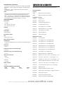
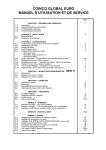
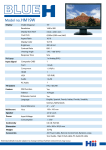
Telecommunications 2854S/2855S Digital Analyzers Digital testers for PCM and data applications up to 140 Mbit/s including mux/demux • PCM and data pattern generator and error detector from 50 bit/s to 140 Mbit/s • Demultiplex and hierarchical errors and alarms monitoring • Generate and monitor test patterns, framed or unframed, at all hierarchical levels within 8, 34 and 140 Mbit/s signals • All data test interfaces as standard: RS-232, X.21 (X.24), V.35, RS-449 (V.36) (2855S), codirectional, contradirectional with EUROCOM optional (2854S and 2855S) • DS3 and LVDS test interface accessories • Data interface and analog channel access • G.821, G.921, G.826, M.2100 and G.962 analysis • Measurements include propagation delay, frequency deviation, frequency and level measurement, DTMF and CAS • DC power and internal battery options • Remote control via RS-232 or IEEE-488 with optional PC applications software • 2850B and 2851 full functionality The 2855S Digital Communications Analyzer extends the capabilities of the 285X series of analyzers to include support of the latest service offerings from PTTs world-wide. Testability from data communications interfaces to high speed digital links and multiplexes at 2, 8, 34, and 140 Mbit/s in a single portable and battery operated unit provides unrivalled flexibility for support of modern digital and data networks and equipment. The 2854S Digital Transmission Analyzer provides most of this functionality but limits the data test capability to Codirectional and Contradirectional interfaces. This Data Sheet, therefore, contains only those capabilities and specifications which are incremental to 2850B and 2851. PCM Framing Systems 2854S and 2855S are able to generate and receive all commonly used framing systems up to 140 Mbit/s for the European digital hierarchy. North American rates are also available to 6 Mbit/s. The instrument can be optioned as European or hybrid versions, and this includes a mixed rate version (European plus North American). Thus 2854S and 2855S have the flexibility to address global applications, including operation in International Gateways where there is a requirement to test mixtures of European and North American traffic carried on satellite systems. 56 kbit/s and 64 kbit/s Channel Testing Individual channels within T1, 704, 2048, 8448 (G.704/G.744 and G.742), 34368 and 139264 kbit/s can be tested at 64 or 56 kbit/s, assisting in testing and fault location within digital data networks and cross-connect switches. n x 64 kbit/s Channel Testing The expanding services at n × 64 kbit/s can be tested where they are carried within T1, 704, 2048, 8448, 34368 and 139264 kbit/s digital signals. All systems and n × 64 kbit/s cross connect switches are catered for with the flexibility of contiguous and non-contiguous channel selection. For the very latest specifications visit www.aeroflex.com Tributary Testing Drop and Insert 2048 kbit/s tributaries within 8448 kbit/s digital signals, 2048 and 8448 kbit/s tributaries within 34368 kbit/s digital signals, and 2048, 8448 and 34368 kbit/s tributaries within 139264 kbit/s digital signals, can be tested to ensure correct functioning of multiplexes. In addition to checking error performance of selected 64 kbit/s and n × 64 kbit/s channels with transmitter and receiver operating independently, a Drop and Insert configuration can be adopted for 704, 2048 and 1544 kbit/s systems so that 64 kbit/s and n × 64 kbit/s channels can be tested with minimum disruption of service to other intraffic channels. Unstructured Where the structures on digital links do not conform to the usual CCITT Recommendations, for example inter-computer links, tests can be performed using an unframed format. DATA INTERFACE TESTING All commonly used data interfaces are provided as standard to give a comprehensive data test capability together with primary, second, third and fourth order PCM rate testing. Thus PCM and data circuits and equipment can be tested with one compact, fully integrated test instrument, from 50 bit/s to 140 Mbit/s. Data test interfaces provided are RS-232, X.21, RS-449 (V.36), V.35 (2855S), codirectional and contradirectional (2854S and 2855S). DTE is standard, DCE optional. Modes Both synchronous and asynchronous modes are possible with a wide range of standard and user programmable data rates, so that traditional data interface testing can be addressed together with modern digital data services at 64 kbit/s, n × 64 kbit/s and other rates. DS3 INTERFACE TESTING The DS3 POD enables unframed BER testing on DS3 interfaces at 44.736 Mbit/s. LVDS INTERFACE TESTING The TTL to LVDS converter accessory enables BER testing on LVDS interfaces at rates from 6 to 50 Mbit/s. IN-SERVICE AND OUT-OF-SERVICE MEASUREMENTS 2854S and 2855S are equally suited to both installation and in-service maintenance measurements at rates up to 140 Mbit/s. Interfaces are provided to enable the receiver to be connected to a number of network points at varying impedances and signal sensitivities, including the provision of automatic equalisation (automatic line build out, ALBO) at 2048 kbit/s. DEMULTIPLEX MONITORING External Access Access is provided on front panel connectors to selected transmit and receive channels, at both analog and digital levels, for first, second, third and fourth order digital signals. Thus, if required, external analog or digital test equipment can be connected to make specific channel measurements beyond the capability of 2854S and 2855S. TERMINAL EQUIPMENT TESTING 2854S and 2855S are able to simulate and detect alarm conditions associated with the various framing systems, so that terminal equipment can be tested for correct operation. This includes the ability to generate programmable Frame or Code Errors to check equipment thresholds. It is also possible to test across multiplexes by inserting and monitoring test patterns within 2048, 8448 and 34368 kbit/s tributaries. In addition, there are automatic test sequences for checking Frame and Multiframe Alignment Strategy, and access is allowed to control and display the condition of all unassigned frame bits. RS-232 REMOTE OPERATION Remote unattended operation can be accomplished via an RS-232 port, which can also be used for local printing. Keyboard functions can be duplicated via RS-232 enabling complete remote reconfiguration and reporting of results. IEEE-488 (GPIB) IEEE-488 can be specified as an option in addition to the standard RS-232 for factory test and laboratory applications or where IEEE488 is preferred. POWER OPTIONS In addition to mains power, options are provided for battery and DC power to cater for all operational requirements including factory, exchange and field. Comprehensive and flexible in-service monitoring is provided to enable simultaneous measurement of framing and CRC errors for a complete demultiplex path for 8448, 34368 and 139264 kbit/s signals. At the same time selected 64 kbit/s or n × 64 kbit/s channels, or 2048, 8448 or 34368 kbit/s tributaries, can be monitored for pattern errors, whilst analog channels can be monitored using the loudspeaker. Both Channel Associated and DTMF Signaling can be monitored within selected 2048 kbit/s tributaries, and alarms are monitored for the full demultiplex path. FRAMING AND BIT RATES CHANNEL ACCESS Permitted combinations of bit rates Digital access is provided to transmit and receive timeslots in 704, 2048, 1544 and 8448 kbit/s (G.744) digital signals, or to 2048 kbit/s tributaries within 8448, 34368 and 139264 kbit/s digital signals. Analog access is possible only at 1544 and 2048 kbit/s, or within 2048 tributaries of 8448, 34368 and 139264 kbit/s signals. SPECIFICATION PCM TRANSMIT INTERFACE As 2850B, 2851 PLUS 34368 kbit/s - G.751 asynchronous 139264 kbit/s - G.751 asynchronous 2048 & 8448 & 34368 & 139264 kbit/s or 704 & 2048 & 8448 & 34368 & 139264 kbit/s or 1544 & 2048 & 8448 & 34368 & 139264 kbit/s or 704 & 2048 & 8448 & 1544 & 3152 & 6312 & 34368 & 139264 kbit/s. TEST PATTERNS AIS Unframed all ones signal CLOCK SOURCE Internal, external or derived from the received signal Internal 34 and 140 Mbit/s Accuracy ±2 ppm from 0°C to 55°C Offset ±100 ppm Insertion Single Channel Selected 64 kbit/s channel of framed signal at 2048 kbit/s or 8448 kbit/s (G.744). Selected 64 kbit/s channel of 2048 kbit/s tributary.(8, 34 and 140 Mbit/s output), or 8448 kbit/s (G.744) tributary (34 and 140 Mbit/s output). n x 64 kbit/s Channel Selected n x 64 kbit/s channel of framed signal at 2048 kbit/s or 8448 kbit/s (G.744). External Selected n x 64 kbit/s channel of 2048 kbit/s tributary (8, 34 and 140 Mbit/s output). Unframed and Multiplex Clock Channel distribution can be contiguous or non-contiguous. BNC connector Range 2048 kbit/s Tributary Selected 2048 kbit/s tributary (8, 34 and 140 Mbit/s output) 6 MHz to 160 MHz Interface 8448 kbit/s Tributary Selected 8448 kbit/s tributary (34 and 140 Mbit/s output) Sine or square wave (ECL/TTL) Impedance 34368 kbit/s Tributary Selected 34368 kbit/s tributary (140 Mbit/s output) 50 Ω Unframed CLOCK OUTPUT TTL or ECL into 75 Ω LINE CODES CMI, AMI (50% duty cycle), HDB3, NRZ MAIN OUTPUTS 34 and 140 Mbit/s Unbalanced Impedance Unframed signal PRBS 34 and 140 Mbit/s 215 -1, 218 -1, 220 -1, 223 -1, 225 -1, 228 -1, 231 -1 All zeros Continuous sequence of 0000 All ones Continuous sequence of 1111 75 Ω Alternating Peak Voltage 34 Mbit/s Alternating sequence of 1010 Word 1.0 V ±0.1 V 140 Mbit/s 0.5 ±0.05 V Space Voltage 0 V ±10% peak NRZ DIGITAL OUTPUT 34 and 140 Mbit/s Unframed only with external clock Frequency Range 6 to 160 Mbit/s Level User programmable sequence of 24 (34 and 140 Mbit/s only), 16 or 8 bits 8 + 8 word Two user programmable 8 bit sequences are alternated by an external TTL input. The changeover occurs at the end of 8 bits (not at 34 or 140 Mbit/s). 1 kHz 0 dBm0 sine wave Digital representation of a sinusoidal signal of 1 kHz at a nominal level of 0 dBm0, coded according to A-Law, inserted into single channel. This facility is available for 704 and 2048 kbit/s systems only. FILL PATTERNS All other channels in single channel and n x 64 kbit/s framed operation PRBS, 215 -1 TTL or ECL to 50 Mbit/s ECL above 50 Mbit/s Connector User programmable 8 bit word 34 and/or 8 and/or 2 Mbit/s tributaries All 1s, All 0s, PRBS, Alternating 10 Data - main digital output BNC Copy of 2 or 8 or 34 Mbit/s test signal Clock - BNC on rear panel For the very latest specifications visit www.aeroflex.com EXTERNAL VOICE and DATA For framed and multiplex operation, an externally input 64 kbit/s data stream or a voice frequency signal can be inserted into one of the channels in the transmitted signal instead of a test pattern. Data Input Applies to frame structures at 704, 1544, 2048 and 8448 kbit/s (G.704/G.744). Applies to 2048 kbit/s tributaries within frame structures at 8448 kbit/s (G.742), 34 and 140 Mbit/s (G.751) and 8448 kbit/s (G.744) tributaries within 34 and 140 Mbit/s. Data Input Interface Codirectional to G.703 Contradirectional to G.703 (AMI 100% or Bipolar NRZ) X.21, RS-449 (V.36), V.35 (using DCE adaptor cable accessory) NRZ (TTL level) VOICE FREQUENCY INPUT Applies to frame structures at 1544 and 2048 kbit/s Applies to 2048 kbit/s tributaries within frame structures at 8448 kbit/s (G.742), 34 and 140 Mbit/s (G.751) Range 0.3 to 3.4 kHz Encoding A-law for 2048 kbit/s µ-Law for 1544 kbit/s Impedance 600 Ω balanced Max Input Level +3 dBm0 ERROR INJECTION 34 and 140 Mbit/s Target Test Pattern Framing Error Type Binary Bits are inverted before coding Code 3×10⁻³ to 1×10⁻⁷ (frame) ACCESS TO STRUCTURE BITS 34 and 140 Mbit/s Frame alignment strategy Change unassigned, distant, and alarm bits PCM RECEIVER INTERFACE FRAMING AND BIT RATES As Transmitter Permitted combinations of bit rates As Transmitter Frequency Tolerance As 2850B, 2851 PLUS 34368 kbit/s ±60 ppm 139264 kbit/s ±60 ppm LINE CODES As Transmitter DIGITAL INPUT Connector BNC Impedance 75 Ω unbalanced NRZ DIGITAL INPUT 34 and 140 Mbit/s Unframed only Frequency Range 6 to 160 Mbit/s Level TTL or ECL to 50 Mbit/s, ECL above 50 Mbit/s Connector Data - main digital output BNC Clock - BNC on rear panel INPUT MODES AND SENSITIVITY 34 and 140 Mbit/s Code errors are injected by changing ±1 to 0 and 0 to ±1 where the polarity of the inserted mark is the same as the polarity of the last mark transmitted. Terminated There is no injection into CMI line code at 140 Mbit/s. Sensitivity Terminates the line Injection Mode ±1 V (34 Mbit/s), ±0.5V (140 Mbit/s), nominal Singly +3 dB -12 dB cable attenuation By keypress Fixed rate 34 Mbit/s 3×10⁻² to 1×10⁻⁸ (pattern and code) 3×10⁻² to 1×10⁻⁷ (frame) 140 Mbit/s 3×10⁻³ to 1×10⁻⁹ (pattern) +3 dB -18 dB linear attenuation Monitor Connects to a protected monitor point Sensitivity Nominal attenuation of 15, 20, 26 and 30 dB +3 dB -6 dB cable attenuation +3 dB -12 dB linear attenuation Maximum total attenuation 38 dB Clock output 64 kHz (TTL) TEST PATTERNS Voice Frequency Output Source Applies to frame structures at 1544 and 2048 kbit/s. Single Channel Applies to 2048 kbit/s tributaries within frame structures at 8448 kbit/s (G.742), 34 and 140 Mbit/s (G.751). Selected 64 kbit/s channel of framed signal at 2048 kbit/s or 8448 kbit/s (G.744). Selected 64 kbit/s channel of 2048 kbit/s tributary. (8, 34 and 140 Mbit/s input), or 8448 kbit/s (G.744) tributary (34 and 140 Mbit/s input). Range 0.3 to 3.4 kHz Decoding n x 64 kbit/s Channel A-Law for 2048 kbit/s Selected n x 64 kbit/s channel of framed signal at 2048 kbit/s or 8448 kbit/s (G.744). µ-Law for 1544 kbit/s Selected n x 64 kbit/s channel of 2048 kbit/s tributary (8, 34 and 140 Mbit/s input). Channel distribution can be contiguous or non-contiguous. Impedance 600 Ω balanced STATUS INDICATORS 2048 kbit/s Tributary A combination of LEDs and an alarm page indicate frame structure alarm conditions for the input signal and, for demultiplex operation, the tributaries selected. 8448 kbit/s Tributary Selected 2048 kbit/s tributary (8, 34 and 140 Mbit/s input). For Demux mode hierarchical AIS, FRAME and DISTANT alarms are ORed to the LED indicator. Selected 8448 kbit/s tributary (34 and 140 Mbit/s input). 34368 kbit/s Tributary UNASSIGNED FRAMING BITS Selected 34368 kbit/s tributary (140 Mbit/s input) The state of the unassigned bits is displayed Unframed DATA TEST INTERFACES Unframed signal X.21 (X.24), RS-449 (V.36), V.35 and RS-232 PRBS As 2851 (2855S only) 34 and 140 Mbit/s TEST PATTERNS 215 -1, 218 -1, 220 -1, 223 -1, 225 -1, 228 -1, 231 -1 As 2851 Repetitive Word ERROR INJECTION Any word which repeats over a 24 bit (34 and 140 Mbit/s only), 16 bit or 8 bit sequence. As 2851 ALARMS CHANNEL EXTRACT For framed single channel and demultiplex operation a selected 64 kbit/s channel is extracted from the received signal and output as a data signal or voice frequency signal. The audio output is also available on the internal loudspeaker. Applies to frame structures at 704, 1544, 2048 and 8448 kbit/s (G.704/G.744). Applies to 2048 kbit/s tributaries within frame structures at 8448 kbit/s (G.742), 34 and 140 Mbit/s (G.751) and 8448 kbit/s (G.744) tributaries within 34 and 140 Mbit/s. Codirectional to G.703 Contradirectional to G.703 (100% AMI or Bipolar NRZ) X.21, RS-449 (V.36), V.35 (using DCE adaptor cable accessory) NRZ (TTL level) Frame or AIS alarm detected All 1's transmitted Signal loss detected Outputs are off For the very latest specifications visit SYNC OUTPUTS As 2851 ERRORS OUTPUT Data Output Data Output Interface As 2851 As 2851 MEASUREMENTS ERROR TYPES PCM Interfaces Line Code Errors (Bipolar Violations) Pattern Errors Framing Errors CRC Errors Data Interfaces Pattern Errors Line Code Errors Measured on input signal www.aeroflex.com Framing Errors Measured at each hierarchical level for the demultiplex path selected Pattern Errors Measured for the selected test pattern which can be a tributary, 64 kbit/s, n x 64 kbit/s channel, or unframed. CRC Errors Measured as appropriate for selected input signal, or 2048 kbit/s tributaries MAIN PARAMETERS As 2851 ADDITIONAL PARAMETERS As 2851 G.821 ERROR PERFORMANCE As 2851 STORED RESULTS As 2851 PROPAGATION DELAY 34 and 140 Mbit/s Range Up to 8 seconds Resolution 1 bit 4 bits at 140 Mbit/s Update rate Typically up to 8 seconds SIGNALING BIT RATE MEASUREMENT The bit rate is measured every other second and displayed to the nearest 1 Hz, or 4 Hz at 140 Mbit/s Accuracy ±2 ppm, ±1 count DIGITAL SIGNAL LEVEL MEASUREMENT The amplitude of the incoming digital signal is measured and displayed in Volts peak and dB relative to nominal 34 and 140 Mbit/s Range +3 to -40 dB Accuracy +3 to -30 dB ±2 dB -30 to -40 dB ±3 dB 2 CHANNEL SYNCHRONIZATION MEASUREMENT As 2851 DS3 POD (External Accessory) Provides DS3 test interface by converting TTL data and clock signals to DS3 signals DS3 signals DS3 Out DS3 In Bit Rate 44.736 Mbit/s Line Code B3ZS Transmit Clock Internal Recovered from the receiver Transmit Frequency Deviation Nominal +50 ppm -50 ppm Signal Format Unframed TTL Connections Transmit Data In Transmit Clock Out Receive Data Out Receive Clock Out Connectors DS3 TTL BNC BNC Power The pod is powered from a mains supply accessory. TTL to LVDS CONVERTER (External Accessory) Provides LVDS test interface by converting TTL data and clock signals to LVDS signals Signals Transmit Data Out Transmit Clock In Receive Data In Receive Clock in Bit Rate 6 to 50 Mbit/s Connectors TTL LVDS BNC 37 Way D type ISO 4902 LVDS Pinout Signal Pin Transmit Data Out Transmit Clock In Receive Data In Receive Clock In 6, 24 8, 26 4, 22 17, 35 Power +5 V taken from 25 Way D Type Auxilliary connector GENERAL CHARACTERISTICS As 2851 except IEEE-488 (Option) Used for remote control or printer operations. ELECTROMAGNETIC COMPATIBILITY VERSIONS AND ACCESSORIES Conforms with the protection requirements of the EEC Council Directive 89/336/EEC. Conforms with the limits specified in the following standards: IEC/EN61326-1 : 1997, RF Emission Class B, Immunity Table 1, Performance Criteria B When ordering please quote the full ordering number information. Ordering Numbers Versions Safety Conforms with the requirements of EEC Council Directive 73/23/EEC (as amended) and the product safety standard IEC/EN 61010-1 : 2001 + C1 : 2002 + C2 : 2003 for Class 1 portable equipment, for use in a Pollution Degree 2 environment. The instrument is designed to be operated from an Installation Category 1 or 2 supply. 2854S Digital Transmission Analyzer 2855S Digital Communications Analyzer Supplied Accessories 43129/003 Supply Lead AC Operation 41690/485 Stowage Cover AC Voltage 46884/604 Audio Jack Plug (Quantity 2) 230 V nominal. 190 to 264 V 46884/403 15 way D-Type Connector 54311/125 X.21 Adaptor Lead - V.11 DTE 54311/127 RS-449 Adaptor Lead - V.11 DTE 54311/131 V.35 Adaptor Lead - DTE 46882/128 Operating Manual DC Operation (Option) 46882/127 Introductory Guide 48 V Optional Accessories POWER REQUIREMENTS 115 V nominal. 90 to 120 V Frequency 45 to 66 Hz Consumption 80 VA maximum Range ±36 to ±60 V Battery Operation (Option) Operating time 1½ hours with backlight timeout of 5 minutes for temperature range of 17 to 27°C Charge time 15 hours Temperature range for full nominal charge 10 to 30°C Temperature range for full nominal discharge 0 to 50°C Limit range of operation Charge 0 to 35°C Discharge 0 to 50°C Weight of battery 2.7 kg INSTRUMENT DIMENSIONS AND WEIGHT Height Width Depth 197 mm 345 mm 477 mm Weight 8 kg For the very latest specifications visit 46880/004 Service Manual 54311/126 X.21 Adaptor Lead - V.10, DTE female 54311/140 X.21 Adaptor Lead - V.11, DCE female 54311/141 X.21 Adaptor Lead - V.10, DCE female 54311/128 RS-449 Adaptor Lead - V.10, DTE female 54311/142 RS-449 Adaptor Lead - V.11, DCE female 54311/143 RS-449 Adaptor Lead - V.10, DCE female 54311/144 V.35 Adaptor Lead - DCE female 54311/152 RS-232 Adaptor Lead - DCE female 54311/121 RS-232 Lead - male to male - 25 way D-Type - 1.5 m 54311/122 X.21 Lead - male to male - 15 way D-Type - 1.5 m 54311/147 RS-449 Lead - male to male - 37 way D-Type - 1.5 m 82520 RS-449 to RS-530 adapter lead, 1.5 m, male to male 54311/148 V.35 Lead - male to male - 37 way D-Type - 1.5 m 54311/130 Co/contradirectional Test Lead - 15 way D-Type 43129/189 IEEE-488 Lead 46662/387 RS-232 Null Modem (female to male) 54717/040 Kyosha printer including power supply and data lead 46662/620 Kyosha paper 10 pack 46883/805 Signal Lead balanced (CF-CF) 54311/210 Signal Lead unbalanced (BNC-BNC) www.aeroflex.com 46662/388 BNC to 1.6/5.6 adaptor 46884/402 D-Type connector 25 way 46662/192 Transit Case 54112/157 Soft Carrying Case 49000/002 Remote Applications Software, single user licence 49000/003 Remote Applications Software, 20 user licence 46883/852 Null Modem (female to female) 46883/824 Gender changer (female to female) 54127/309 Rack Mount Kit 80016 TTL to LVDS Converter 80018 DS3 POD Note that 2854S does not provide RS-232, X.21, RS-449 and V.35 test interfaces Option 01 02 03 04 08 09 12 13 19 22 25 26 Allowed Combinations † † † † † † † † † † † † † † † † † † † † † † † † † † † † † Description 2, 8, 34 and 140 Mbit/s Framed and Mux/Demux Add 1544 kbit/s (T1) Add 704 kbit/s Add 704 kbit/s, T1, T1C, T2 (No ALBO) French key panel 1.6/5.6 Connectors 15 Battery IEEE-488 DC Input - ±36 to ±60 V (includes cable) EUROCOM D/1 IB6 EUROCOM D/1 IB5 & IB6 V.11 data rate to 9 Mbits/s Basic options. † Additional options. CHINA Beijing Tel: [+86] (10) 6539 1166 Fax: [+86] (10) 6539 1778 GERMANY Tel: [+49] 8131 2926-0 Fax: [+49] 8131 2926-130 SCANDINAVIA Tel: [+45] 9614 0045 Fax: [+45] 9614 0047 CHINA Shanghai Tel: [+86] (21) 5109 5128 Fax: [+86] (21) 5150 6112 HONG KONG Tel: [+852] 2832 7988 Fax: [+852] 2834 5364 SPAIN Tel: [+34] (91) 640 11 34 Fax: [+34] (91) 640 06 40 FINLAND Tel: [+358] (9) 2709 5541 Fax: [+358] (9) 804 2441 INDIA Tel: [+91] 80 5115 4501 Fax: [+91] 80 5115 4502 UK Burnham Tel: [+44] (0) 1628 604455 Fax: [+44] (0) 1628 662017 FRANCE Tel: [+33] 1 60 79 96 00 Fax: [+33] 1 60 77 69 22 KOREA Tel: [+82] (2) 3424 2719 Fax: [+82] (2) 3424 8620 UK Cambridge Tel: [+44] (0) 1763 262277 Fax: [+44] (0) 1763 285353 As we are always seeking to improve our products, the information in this document gives only a general indication of the product capacity, performance and suitability, none of which shall form part of any contract. We reserve the right to make design changes without notice. All trademarks are acknowledged. Parent company Aeroflex, Inc. ©Aeroflex 2006. UK Stevenage Tel: [+44] (0) 1438 742200 Fax: [+44] (0) 1438 727601 Freephone: 0800 282388 USA Tel: [+1] (316) 522 4981 Fax: [+1] (316) 522 1360 Toll Free: 800 835 2352 w w w.aeroflex.com [email protected] Our passion for performance is defined by three attributes represented by these three icons: solution-minded, performance-driven and customer-focused. Part No. 46891/050, Issue 11, 10/06