1
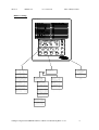
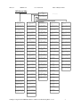
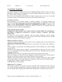
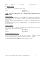
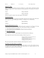
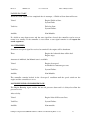
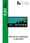
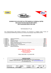
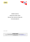
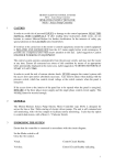
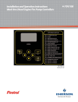
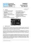
FD4e.v4
OPFD4e-V4
Iss 4 2-June 09
Metron Eledyne LTD.
1.
PREFACE. ...................................................................................................................................................... 3
2.
CAUTION. ...................................................................................................................................................... 3
3.
GENERAL. ..................................................................................................................................................... 3
4.
VOLT FREE CONTACTS............................................................................................................................ 4
5.
SUPPLY CONNECTIONS. .......................................................................................................................... 4
6.
OPERATOR INTERFACE DEVICE OID DISPLAY. .............................................................................. 5
SYSTEMS STATUS. (BOTH LANGUAGES) .......................................................................................................... 8
SYSTEM LOGS. (BOTH LANGUAGES) ................................................................................................................. 8
CONFIG. (BOTH LANGUAGES) ............................................................................................................................. 8
7.
ENERGISING THE CONTROL SYSTEM. ............................................................................................... 9
8.
LAMP TEST. .................................................................................................................................................. 9
9.
RESET. ........................................................................................................................................................... 9
10.
MUTE.............................................................................................................................................................. 9
11.
AC SUPPLY MONITORING. ...................................................................................................................... 9
AC SUPPLY FAILURE...................................................................................................................................... 10
12.
HEATERS. ................................................................................................................................................... 10
ENGINE HEATER (OPTION). ............................................................................................................................ 10
PANEL HEATER (OPTION). .............................................................................................................................. 10
13.
DC SUPPLY MONITORING. .................................................................................................................... 10
BATTERY VOLTAGE AND CURRENT. ......................................................................................................... 10
BATTERY FAILURE. ....................................................................................................................................... 10
14.
BATTERY CHARGING. ............................................................................................................................ 12
15.
CHARGER MONITORING. ...................................................................................................................... 13
CHARGER FAILURE. ....................................................................................................................................... 13
16.
MANUAL MODE. ....................................................................................................................................... 14
MANUAL START. ............................................................................................................................................ 14
ENGINE RUNNING. ......................................................................................................................................... 14
ENGINE SHUTDOWN (MANUAL). ................................................................................................................ 14
17.
AUTOMATIC MODE. ................................................................................................................................ 15
LOW PRESSURE AUTOSTART. ..................................................................................................................... 15
DELUGE VALVE. ............................................................................................................................................. 15
REMOTE START............................................................................................................................................... 16
ENGINE RUNNING. ......................................................................................................................................... 16
ENGINE SHUTDOWN IN AUTO. .................................................................................................................... 16
18.
CRANK SEQUENCE. ................................................................................................................................. 16
BATTERY FAILURE DURING CRANKING. ................................................................................................. 16
FAILED TO START........................................................................................................................................... 17
19.
OVERSPEED. .............................................................................................................................................. 17
20.
ENGINE LUBE OIL PRESSURE LOW. .................................................................................................. 17
F:\Engineering\Standards\EFP-FD4e\FD4e-v4\FD4e-V4 Manuals\OpFD4e-v4.doc
1
FD4e.v4
OPFD4e-V4
Iss 4 2-June 09
Metron Eledyne LTD.
21.
ENGINE HIGH WATER TEMPERATURE. ........................................................................................... 18
22.
ENGINE FUEL LEVEL LOW. .................................................................................................................. 18
23.
WEEKLY TEST START. ........................................................................................................................... 18
24.
SPEEDSWITCH FAILURE ....................................................................................................................... 18
25.
CONTACTOR COIL FAILURE ................................................................................................................ 19
26.
SD MEMORY CARD .................................................................................................................................. 19
27.
DISPOSAL.................................................................................................................................................... 19
F:\Engineering\Standards\EFP-FD4e\FD4e-v4\FD4e-V4 Manuals\OpFD4e-v4.doc
2
FD4e.v4
OPFD4e-V4
Iss 4 2-June 09
Metron Eledyne LTD.
OPERATING INSTRUCTIONS FOR CONTROLLER:
TYPE: EFP/FD4e
1. PREFACE.
This operating manual explains the operation of the complete control system.
2. CAUTION.
In order to avoid risk of personal INJURY or damage to the control equipment, READ THIS
MANUAL VERY CAREFULLY. If after reading these instructions doubt exists, do not
hesitate to contact Metron-Eledyne for further clarification.
In the interests of safety pay special attention to the CAUTION notes listed below:
If work has to be carried out on the engine or control equipment, isolate the control equipment
from the A.C and D.C supplies, and remove the start solenoid supplies from control circuit
terminals before work commences. If possible use a temporary label, which draws attention to
this fact.
Before attempting to start the engine during commissioning, ensure that the 'Fuel Stop
Solenoid' is operational. Due to the nature of the equipment, the control system may start the
engine at any time when operating in automatic mode. Ensure all concerned are aware of this
condition by means of an appropriate label, prominently displayed on the engine skid.
When the equipment is energised and on line, ensure all doors are closed and where applicable
locked.
If during commissioning the equipment is energised with the access door to the panel interior
open, make sure that any terminal cover is fitted to avoid the risk of electric shock.
3. GENERAL.
The controller is designed as a fully automatic engine start system based on the requirements of
National Fire Codes NFPA No. 20 for Engine Driven Fire Pump Controllers, IEC 62091,
UL218 and to FM class number 1321/1323.
In these instructions, the following terms used are defined as: Visual
- Lamp, or meter.
Display
- LCD display on the front door (OID).
Audible
- Electronic sounder.
Volt free
- Remote volt free changeover contacts.
F:\Engineering\Standards\EFP-FD4e\FD4e-v4\FD4e-V4 Manuals\OpFD4e-v4.doc
3
FD4e.v4
OPFD4e-V4
Iss 4 2-June 09
Metron Eledyne LTD.
4. VOLT FREE CONTACTS.
If the volt free is named then its title is active i.e.
Volt Free.
Engine Running.
Indicates the contacts are in the engine running position.
If the volt free engine running is said to clear i.e.
Volt Free.
Engine Running clears.
Indicates the contacts have changed to the standby position (engine stopped).
5. SUPPLY CONNECTIONS.
Ensure the system is correctly earthed and make interconnections referring to information
contained in the interconnection drawing. Connect AC and DC supplies.
F:\Engineering\Standards\EFP-FD4e\FD4e-v4\FD4e-V4 Manuals\OpFD4e-v4.doc
4
FD4e.v4
OPFD4e-V4
Iss 4 2-June 09
Metron Eledyne LTD.
6. OPERATOR INTERFACE DEVICE OID DISPLAY.
The Operator Interface Device (OID) provides visual indication of the alarms, status of system
parameters, and an interface to change set points to configure the FD4e to operate
appropriately for various installation requirements.
Common Tasks Performed Using The OID
Annunciator
Silencing Horn: If a horn is sounding and the alarm is
silence able, a quick press of the [SILENCE/LAMPTEST]
will silence the horn (less than 1 second press).
Resetting Alarms: If the alarm condition has cleared,
press the [RESET/ESC] button BRIEFLY to reset alarms.
Operating Mode Change: The operational mode that the
controller is in can be changed via the mode switch and by
the OID push buttons. With the mode switch in the
‘AUTO’ (automatic) position, the ‘AUTO’ indicator will
be illuminated and the controller will be in full automatic
start mode. The test push button is only active while the
mode switch is in the automatic position. When the mode
switch is on the ‘MAN’ (manual) position, the
‘MANUAL’ indicator will be illuminated and the
controller will be available for manual starting only.
When the mode switch is in the off position, neither the
AUTO or MAN indicator is illuminated.
Test Mode: When controller is in Auto Mode, pressing
and holding the [TEST] button for two or more seconds
will open the pressure drain solenoid thus dropping the
pressure which causes the controller to start the engine.
Pressing and releasing the [TEST] button in Manual Mode
Push buttons
LCD Display
directly controls the opening and closing of the drain
solenoid. The engine will not automatically start when in
Manual Mode.
Lamp Test: To illuminate and check all the OID LED’s
and the horn, press and hold the [SILENCE/LAMPTEST]
button 5 or more seconds or until all the lights turn on.
The Controller may be configured as either "Manual" or "Automatic" stop as required (System
Config Screen 104). "Manual" stop is set as standard. The current status of this setting is
visible on the Main System Status Screen where the letter “A” will appear in the upper right hand
corner of the screen when set to Automatic Stop and an “M” will appear when set for Manual
stop.
F:\Engineering\Standards\EFP-FD4e\FD4e-v4\FD4e-V4 Manuals\OpFD4e-v4.doc
5
FD4e.v4
OPFD4e-V4
Iss 4 2-June 09
Metron Eledyne LTD.
OID Screen Map
METRON OID100
LOSS OF DC POWER
POWER
1
2
SYSTEM
STATUS
SYSTEM
LOGS
CONFIG
3
PRINT
CHANGE/
ENTER
AUTO
MANUAL
TEST
RESET/
ESC
SILENCE
/LAMP
TEST
SYSTEM LOGS
1) Event Log
2) Pressure Log
1
SYSTEM STATUS A
PRES STRT BAT1 BAT2
110
100
13V 13V
psi
psi
6A
0A
1
CONFIG
1) SYSTEM SETPOINTS
2) USER PREFERENCES
3) TECH SCREENS
2
SYSTEM STATUS
Engine Countdown Tmr
0sec Until Start
0min Until Stop
3
SYSTEM STATUS
Engine Countdown Tmr
For AC Power Outage
0min Until Start
2
CONFIG
1) ANALOG SIGNALS
2) AUXILLIARY ALARMS
#
1 EVENT LOG
System in Off
Mode Occurred
02/16/03 13:15:15
4
SYSTEM STATUS
Engine Hrs:
5.3
# Of Starts:
8
Mon02/17/03 17:53:26
#
5
SYSTEM STATUS
Firmware Ver SV 1.1
Commissioned Date:
11/15/02
#
1 EVENT DETAILS
Pressure: 83.2psi
System Auto:Yes
Engine Running:No
6
SYSTEM STATUS
Extended Voltage
BAT 1 27.10
0.00A
BAT 2 27.05
0.00A
#
1 EVENT DETAILS
Charger #1 OK:Yes
Charger #2 OK:Yes
Battery #1 OK:Yes
#
1 EVENT DETAILS
Battery #2 OK:Yes
AC Power Avail:Yes
Low Fuel Level:No
1 EVENT DETAILS
System in Off
Mode Occurred
02/16/03 13:15:15
PRESSURE LOG
02/16/03 17:52:45
112 psi
Skip Rate:[EACH ]
Continued on next
page.
PRESSURE LOG
02/16/03 17:52:30
112 psi
Skip Rate:[EACH ]
PRESSURE LOG
02/16/03 17:52:15
113 psi
Skip Rate:[EACH ]
|
|
|
|
|
|
#
2 EVENT LOG
Engine Failed To
Start Alarm Occurred
02/16/03 07:32:15
#
3 EVENT LOG
AC Power Failure
Alarm Cleared
02/16/03 07:09:48
|
|
|
|
F:\Engineering\Standards\EFP-FD4e\FD4e-v4\FD4e-V4 Manuals\OpFD4e-v4.doc
6
FD4e.v4
OPFD4e-V4
Iss 4 2-June 09
OID Screen Map
(continued)
Metron Eledyne LTD.
1
CONFIG
1) SYSTEM SETPOINTS
2) USER PREFERENCES
3) TECH SCREENS
24v Defaults
2
CONFIG
1) ANALOG SIGNALS
2) AUXILLIARY ALARMS
101 SYSTEM SETPOINTS
Engine Start
Pressure
[100.0]psi
0-999.9
201 USER PREFERENCES
Set System Real
Time Clock
[17:03:52]
301 TECH SCREENS
SPECIAL: Engine
Minimum Run Time
[No ]
400 ANALOG SIGNALS
Analog Input 01
Slope:
[0.3401360]
501 AUX USER PROGRAM
AUX# 1
Enabled
[No]
102 SYSTEM SETPOINTS
Engine Stop
Pressure
[110.0]psi
0-999.9
202 USER PREFERENCES
Set System Date
[02/16/03]
302 TECH SCREENS
SPECIAL: Engine
Minimum Run Time
[15]minutes
1-99
401 ANALOG SIGNALS
Analog Input 01
Offset:
[- 76.1904]
502 AUX USER PROGRAM
AUX# 1
Input Number
[30]
0-53
103 SYSTEM SETPOINTS
Engine Start Delay
Time
[ 1] seconds 1-999
203 USER PREFERENCES
Set System Day
Of The Week
[Sun]
303 TECH SCREENS
Energized To Stop
Fuel Solenoid Time
[10]seconds
0-99
402 ANALOG SIGNALS
Analog Input 1 651
Minimum Counts
[ 200]
503 AUX USER PROGRAM
AUX# 1
Input Contact Type
[NO ]
104 SYSTEM SETPOINTS
Engine Automatic
Stop Enabled
[Yes]
204 USER PREFERENCES
Log System Pressure
Drop Events
[Yes]
304 TECH SCREENS
Low Oil Pressure
Alarm Delay Time
[10]seconds
1-99
410 ANALOG SIGNALS
Analog Input 02
Slope:
[0.0352500]
504 AUX USER PROGRAM
AUX# 1
Trip Time
[ 0]sec
0-999
105 SYSTEM SETPOINTS
Engine Minimum
Run Time
[30]minutes
30-99
205 USER PREFERENCES
Low Pressure Event
Trip Pressure
[ 60.0]psi
0-999.9
305 TECH SCREENS
Nominal Battery
Voltage
[24]VDC
10-99
411 ANALOG SIGNALS
Analog Input 02
Offset:
[
0.0000]
505 AUX USER PROGRAM
AUX# 1
Reset Time
[ 0]sec
0-999
106 SYSTEM SETPOINTS
Automatic Weekly
Engine Test Run
[No]
206 USER PREFERENCES
Low Pressure Event
Reset Time
[15] seconds
0-20
306 TECH SCREENS
Battery Low Voltage
Alarm Trip Voltage
[12.0]VDC
6-99
412 ANALOG SIGNALS
Analog Input 2 1174
Minimum Counts
[
0]
506 AUX USER PROGRAM
AUX# 1
Auto Reset Enabled
[Yes]
107 SYSTEM SETPOINTS
Auto Weekly Engine
Test Day Of The Week
[Mon]
207 USER PREFERENCES
Time Between
Pressure Log Samples
[ 15] seconds 15-999
307 TECH SCREENS
Battery Low Voltage
Alarm Trip Time
[ 2]seconds
0-99
420 ANALOG SIGNALS
Analog Input 03
Slope:
[0.0352500]
507 AUX USER PROGRAM
AUX# 1
Horn Enabled
[No ]
108 SYSTEM SETPOINTS
Auto Weekly Engine
Test Start Time
[10:00:00]
208 USER PREFERENCES
Auto Print Each
Pressure Log Sample
[No ]
308 TECH SCREENS
Change Tech Password
[******]
421 ANALOG SIGNALS
Analog Input 03
Offset:
[
0.0000]
508 AUX USER PROGRAM
AUX# 1
Horn Silence
[No ]
109 SYSTEM SETPOINTS
Auto Weekly Test
Length Of Run Time
[30] minutes
30-99
209 USER PREFERENCES
Auto Print Each
Event Log Entry
[No ]
309 TECH SCREENS
Password Logout
Time
[ 5] minutes
1-15
422 ANALOG SIGNALS
Analog Input 3 1225
Minimum Counts
[
0]
509 AUX USER PROGRAM
AUX# 1
LED Number
[ 0]
0-24
110 SYSTEM SETPOINTS
Auto Weekly Test
Oil/Water Shutdown
[No]
210 USER PREFERENCES
Selective Range
Printing
[ 1] Before
1-99
310 TECH SCREENS
System Commissioned
Date
[00/00/00]
ANALOG INPUT COUNTS
649 1176 1221
0
0
0
0
0
0
0
510 AUX USER PROGRAM
AUX# 1
Output1 Number
[ 0]
0-19
111 SYSTEM SETPOINTS
Power Failure Engine
Startup
[No]
211 USER PREFERENCES
Selective Range
Printing
[ 1] After
1-99
311 TECH SCREENS
Expiration Time
For Test Settings
[ 5]minutes
1-60
424 BATTERY 1
Constant A
xA^3 + xB^2 + xC + D
[ 0.0000]
511 AUX USER PROGRAM
AUX# 1
Output2 Number
[ 0]
0-19
112 SYSTEM SETPOINTS
Power Failure Engine
Start Delay Time
[ 1] minutes 0-500
212 USER PREFERENCES
LCD Back Light Mode
0=Always on
[0]]
1=Power Save
312 TECH SCREENS
STARTUP TEST: Test
Settings Enabled
[No ]
425 BATTERY 1
Constant B
xA^3 + xB^2 + xC + D
[ 0.0000]
512 AUX USER PROGRAM
AUX# 1
Output3 Number
[ 0]
0-19
113 SYSTEM SETPOINTS
Pressure Transducer
Failure Engine Start
[Yes]
213 USER PREFERENCES
Language Select
0=English, 1=Spanish
[0]
313 TECH SCREENS
STARTUP TEST: Engine
Minimum Run Time
[15]minutes
1-99
426 BATTERY 1
Constant C
xA^3 + xB^2 + xC + D
[ 0.00978]
513 AUX USER PROGRAM
AUX# 1
Record In Event Log
[No ]
114 SYSTEM SETPOINTS
Surge Control Valve
Open/Close Control
[No ]
214 USER PREFERENCES
Change User Password
Level 1
[****]
314 TECH SCREENS
FACTORY TEST: Test
Settings Enabled
[No ]
427 BATTERY 1
Constant D
xA^3 + xB^2 + xC + D
[- 0.05642]
514 AUX USER PROGRAM
AUX# 1
Text Message Number
[ 0]
0-27
115 SYSTEM SETPOINTS
Surge Control Valve
Delay Time
[ 15] seconds 0-999
215 USER PREFERENCES
Save ALL settings
to SD memory card
[ No]
315 TECH SCREENS
FACTORY TEST: Engine
Crank Time
[15]seconds
1-15
428 BATTERY 1
Volts per count
515 AUX USER PROGRAM
Engine run dependent
[1.0000000]
[No]
116 SYSTEM SETPOINTS
Shutdown On Low
Intake Pressure/Lvl
[No ]
216 USER PREFERENCES
Load ALL settings
from SD memory card
[No]
316 TECH SCREENS
FACTORY TEST: Engine
Crank Rest Time
[15]seconds
1-15
[
117 SYSTEM SETPOINTS
Shutdown On Low
Intake Trip Time
[ 20]seconds
0-999
217 USER PREFERENCES
Pressure Units
[bar]
317 TECH SCREENS
Alarm Log
1/10
Event Log
1/1569
Pr. Log
1/25123
430 BATTERY 2
Constant A
xA^3 + xB^2 + xC + D
[ 0.0000]
118 SYSTEM SETPOINTS
Low Intake Shutdown
Auto Reset
[Yes]
218 USER PREFERENCES
Engine Running chrg
failure alarm
[No]
318 TECH SCREENS
Speed Switch Fail
Delay Time
[10]s
0-99
431 BATTERY 2
Constant B
xA^3 + xB^2 + xC + D
[ 0.0000]
119 SYSTEM SETPOINTS
Low Intake Shutdown
Auto Reset Time
[ 20]seconds
0-999
219 USER PREFERENCES
Charger failure
delay time
[5]
432 BATTERY 2
Constant C
xA^3 + xB^2 + xC + D
[ 0.00978]
120 SYSTEM SETPOINTS
Pressure Switch
Engine Start
[No ]
220 USER PREFERENCES
Modbus Address
[0001]
433 BATTERY 2
Constant D
xA^3 + xB^2 + xC + D
[- 0.05642]
121 SYSTEM SETPOINTS
Deluge Valve
Engine Start
[Yes]
221 USER PREFERENCES
RS485 com port
Setting
[PRINTER]
122 SYSTEM SETPOINTS
High System Pressure
Alarm
[175.0]psi
999.9
222 USER PREFERENCES
Modbus/Printer baud
435 BATTERY 2
Minimum Amps
[9600]
[
0-255
429 BATTERY 1
Minimum Amps
0.1]
434 BATTERY 2
Volts per count
[1.0000000]
0.1]
223 USER PREFERENCES
Modbus Parity
[None]
F:\Engineering\Standards\EFP-FD4e\FD4e-v4\FD4e-V4 Manuals\OpFD4e-v4.doc
7
FD4e.v4
OPFD4e-V4
Iss 4 2-June 09
Metron Eledyne LTD.
The OID can view 3 main areas.
SYSTEMS STATUS. (both languages)
When the controller is switched on the OID will default to System Status screen 1 which
displays the
Fire Main Pressure.
The Start Pressure Setting.
Battery 1 and 2’s voltage and current.
The remaining screens in System Status are not required for normal operation of the controller,
if they are required consult the Service Manual.
SYSTEM LOGS. (both languages)
In System Logs it is possible to view 2 separate logs.
Event Logs (records alarms and system functions).
Pressure Logs (records pressure at set times).
These Logs are not required for normal operation of the controller, if they are required consult
the Service Manual.
CONFIG. (both languages)
In Config it is possible to view 5 separate areas.
System Setpoints. (both languages)
User Preferences. (both languages)
Tech Screen. (both languages)
Analog Signal. (both languages)
Auxiliary alarms. (both languages)
It may be necessary to change the Start Pressure, this can be done in System Setpoints.
To change the Start Pressure press the following pushbuttons in order.
Config button (2) once.
Button 1 (System Logs) once.
Change/Enter button once.
Buttons 1, 2 or 3 to enter the password.
Default value is 1111.
Up and Down buttons to change the digit.
Change/Enter to move to the next digit.
When the new number is complete press
Change/Enter to accept.
System Status
Check that the new Start Pressure is correct.
It may be now necessary to change the Stop Pressure, to do this press the following
pushbuttons in order.
Config button (2) once.
Button 1 (System Logs) once.
Up and Down buttons to scroll screens, go to 102.
F:\Engineering\Standards\EFP-FD4e\FD4e-v4\FD4e-V4 Manuals\OpFD4e-v4.doc
8
FD4e.v4
OPFD4e-V4
Iss 4 2-June 09
Metron Eledyne LTD.
Change/Enter button once.
Buttons 1, 2 or 3 to enter the password.
Default value is 1111.
Up and Down buttons to change the digit.
Change/Enter to move to the next digit.
When the new number is complete press
Change/Enter to accept.
System Status
Check that the new Stop Pressure is correct.
The remaining screens are not required for normal operation of the controller, if they are
required consult the Service Manual.
7. ENERGISING THE CONTROL SYSTEM.
Close all CB’s and close the AC isolator.
Visual.
Power.
Auto Mode (see note).
Battery 1 Healthy
Battery 2 Healthy
Audible.
Silent.
Display shows.
Water Pressure.
Start Pressure.
Battery 1 Volts & Amps.
Battery 2 Volts & Amps.
NOTE.
The controller will energise in the mode according to the mode switch.
8. LAMP TEST.
Press the Silence/Lamp test pushbutton for least 5 seconds.
Visual.
All lamps illuminate.
9. RESET.
To reset an alarm, press the Reset/Esc pushbutton for at least 1 second.
10. MUTE.
To silence an alarm the Silence/Lamp Test pushbutton must be pressed and then released.
11. AC SUPPLY MONITORING.
Switching on the AC isolator will supply the Battery Charger circuit breaker CB1 and CB5
which protectS the Engine Heater circuit.
F:\Engineering\Standards\EFP-FD4e\FD4e-v4\FD4e-V4 Manuals\OpFD4e-v4.doc
9
FD4e.v4
OPFD4e-V4
Iss 4 2-June 09
Metron Eledyne LTD.
AC SUPPLY FAILURE.
Should the AC supply fail the battery chargers will be de-energised, their internal circuit senses
this and after a short delay.
Visual.
AC Power Loss (due to both chargers failing).
Then after a delay of 30 seconds.
Visual.
Charger 1 Failure.
Charger 2 Failure.
System Fault.
Volt free.
System Failure.
Audible.
Non-Mutable.
When the AC supply is restored the AC supply alarms will clear.
12. HEATERS.
ENGINE HEATER (Option).
Engine Jacket Heater supply is protected by CB5 and when switched on will supply the engine
heater via terminals L1 & L2.
PANEL HEATER (Option).
The panel heater supply is protected by fuse F. A thermostat TH controls the panel heater.
With the thermostat TH above ambient.
Heater Warms.
With the thermostat TH below ambient.
Heater Cools.
Set the thermostat to 30 Deg C.
13. DC SUPPLY MONITORING.
BATTERY VOLTAGE AND CURRENT.
Battery voltage and charge current can be viewed on the LCD display mounted on the door.
BATTERY FAILURE.
If a Battery 1 is disconnected.
Visual.
Battery 1 Healthy – goes out
System Fault.
Audible.
Non-Mutable.
F:\Engineering\Standards\EFP-FD4e\FD4e-v4\FD4e-V4 Manuals\OpFD4e-v4.doc
10
FD4e.v4
OPFD4e-V4
Volt free.
Iss 4 2-June 09
Metron Eledyne LTD.
System Failure.
When the battery as been reconnected, the Controller must be reset for the alarms to clear.
If a Battery 2 is disconnected.
Visual.
Battery 2 Healthy – goes out.
System Fault.
Audible.
Non-Mutable.
Volt free.
System Failure.
When the battery as been reconnected, the Controller must be reset for the alarms to clear.
If both batteries are disconnected:
Visual.
Battery 1 Healthy – goes out.
Battery 2 Healthy – goes out
System Fault – on
Loss of DC power - on.
Audible.
Non-Mutable.
Volt free.
System Failure
Not in Auto
F:\Engineering\Standards\EFP-FD4e\FD4e-v4\FD4e-V4 Manuals\OpFD4e-v4.doc
11
FD4e.v4
OPFD4e-V4
Iss 4 2-June 09
Metron Eledyne LTD.
14. BATTERY CHARGING.
This battery charger is intended for use only in Metron Eledyne control systems. Use of an
attachment / connector not recommended or sold by Metron Eledyne may result in a risk of
fire, electric shock, or injury to persons.
Do not in any circumstances disassemble the battery charger, there are no user serviceable
parts inside. Incorrect reassembly may result in risk of electric shock or fire.
WARNING NOTICE
The performance of the battery charger is entirely automatic. No operator variables are
provided, the charger is factory preset to the required float voltage, at a maximum current of 10
Amps and NO ADJUSTMENTS MUST BE ATTEMPTED ON SITE or damage to the
batteries may result. Maintenance of batteries should be carried out in accordance with the
instructions issued by the battery manufacturer.
RISK OF EXPLOSIVE GASSES.
WORKING IN THE VICINITY OF A LEAD ACID/ NI CAD BATTERY IS DANGEROUS .
BATTERIES GENERATE EXPLOSIVE GASSES DURING NORMAL BATTERY
OPERATION.
To reduce the risk of battery explosion read this manual completely, and the battery
manufacturers data. Equipment used in the vicinity of the batteries should also be carefully
selected to reduce the risk of battery explosion.
PERSONAL PRECAUTIONS
1.Someone should be within range of your voice or close enough to come to your aid when you
work near a lead acid/ nicad battery.
2.Have plenty of fresh water and soap nearby in case battery acid contacts skin, clothing or
eyes.
3.Wear complete eye protection and clothing protection. Avoid touching eyes while working
near the battery.
4.If battery acid contacts skin or clothing , wash immediately with soap and water. If acid
enters eye immediately flush with running cold water for at least 10 minutes and get medical
attention immediately.
5.NEVER smoke or allow a spark flame in the vicinity of the battery or the engine.
6.Be extra cautious to reduce the risk of dropping a metal tool onto battery, it may spark or
short the circuit battery or other electrical parts that may cause explosion.
7.Remove personal metal items such as rings, bracelets, necklaces and watches when working
with an engine battery. Such engine batteries can produce a short circuit current high enough
to weld a ring or similar, causing a severe burn.
8.NEVER charge a frozen battery.
PREPARING TO CHARGE
Clean battery terminals. Be careful to prevent corrosion from coming into contact with the
eyes. Study all battery manufacturers specific precautions such as removing or not removing
cell caps during initial charging and verify that the maximum rate of charge is not exceeded.
F:\Engineering\Standards\EFP-FD4e\FD4e-v4\FD4e-V4 Manuals\OpFD4e-v4.doc
12
FD4e.v4
OPFD4e-V4
Iss 4 2-June 09
Metron Eledyne LTD.
15. CHARGER MONITORING.
CHARGER FAILURE.
Should Charger 1 stops charging, its internal circuits will sense this and after a delay of 160
seconds.
Visual.
Charger 1 Failure.
System Fault.
Volt free.
System Failure.
Audible.
Non-Mutable.
If the charger starts to charge again the Charger Failure alarms will clear.
Should Charger 2 stops charging, its internal circuits will sense this and after a delay of 160
seconds.
Visual.
Charger 2 Failure.
System Fault.
Volt free.
System Failure.
Audible.
Non-Mutable.
If the charger starts to charge again the Charger Failure alarms will clear.
F:\Engineering\Standards\EFP-FD4e\FD4e-v4\FD4e-V4 Manuals\OpFD4e-v4.doc
13
FD4e.v4
OPFD4e-V4
Iss 4 2-June 09
Metron Eledyne LTD.
16. MANUAL MODE.
Select manual mode by using the mode selector switch.
Visual.
Manual Mode.
Auto Mode goes out.
NOTE. MANUAL MODE SHOULD ONLY BE USED FOR COMMISSIONING OR
MAINTENANCE.
MANUAL START.
To start, press either ‘Crank Battery 1’ or ‘Crank Battery 2’ pushbuttons, PB1 or PB2, their
contacts will energise the start solenoids via terminals 9 or 10 cranking the engine from their
respective battery.
The battery chargers will be inhibited and the via terminal 1 the ‘Fuel Solenoid’ will be
energised
The pushbutton must be released when the ‘Engine Running’ lamp is illuminated which should
be almost immediate.
ENGINE RUNNING.
When the engine runs up to speed the speedswitch connected to the engine speed sender unit,
will energise the engine running input, terminal 2.
Visual.
Engine Running.
Volt free.
Engine Running.
ENGINE SHUTDOWN (MANUAL).
Pressing the Engine Stop pushbutton PB3 will result in terminal 12 the Energise To Stop
solenoid output energising, and terminal 1 the ‘Fuel Solenoid’ output de-energising.
An AUTOSTART SIGNAL INHIBITS the Engine Shutdown pushbutton.
F:\Engineering\Standards\EFP-FD4e\FD4e-v4\FD4e-V4 Manuals\OpFD4e-v4.doc
14
FD4e.v4
OPFD4e-V4
Iss 4 2-June 09
Metron Eledyne LTD.
17. AUTOMATIC MODE.
Select automatic mode by using the mode selector switch.
Visual.
Auto Mode.
Manual Mode goes out
Volt Free.
Automatic Mode.*
* Note:
When all power is lost to the controller then the volt free contacts will show ‘Not in Auto’
Controller is in now Standby.
Manual start is inhibited.
LOW PRESSURE AUTOSTART.
Should the fire main water pressure fall to below the Engine Start Pressure set point, the
Engine Start Delay timer will be energised. When the timer times out a crank sequences will
begin, the engine will be cranked alternatively from both batteries via terminals 9 or 10 for 15
seconds.
The Engine Start Pressure can be set in System Setpoints screen 101.
The Engine Stop Pressure can be set in System Set Points screen 102.
The Engine Start Delay timer can be set in System Setpoints screen 103.
NOTE: The start pressure MUST be set to a lower value than the stop pressure.
A crank sequences begins, the engine will be cranked alternatively from both batteries via
terminals 9 or 10 for 15 seconds.
Visual.
Pump on Demand.
Volt Free.
Pump on Demand.
If the start signal is removed, the crank sequence will continue.
DELUGE VALVE.
Should a deluge valve signal be received at terminal 16, the Engine Start Delay timer will be
energised. When the timer times out the crank sequence will begin, the engine will be cranked
alternatively from both batteries via terminals 9 or 10 for 15 seconds.
Visual.
Pump on Demand.
Volt Free.
Pump on Demand.
If the start signal be removed, the crank sequence will continue.
F:\Engineering\Standards\EFP-FD4e\FD4e-v4\FD4e-V4 Manuals\OpFD4e-v4.doc
15
FD4e.v4
OPFD4e-V4
Iss 4 2-June 09
Metron Eledyne LTD.
REMOTE START.
Should a remote start signal be received at terminal 17, a crank sequence will begin (no time
delay), the engine will be cranked alternatively from both batteries via terminals 9 or 10 for 15
seconds.
Visual.
Pump on Demand.
Volt Free.
Pump on Demand.
If the start signal be removed, the crank sequence will continue.
ENGINE RUNNING.
When the engine runs up to speed the speedswitch connected to the engine speed sender unit,
will energise the engine running input, terminal 2, cranking will cease immediately..
Visual.
Engine Running.
Volt free.
Engine Running.
ENGINE SHUTDOWN IN AUTO.
Pressing the Engine Stop pushbutton PB3 will result in terminal 12 the Energise To Stop
solenoid output energising, and terminal 1 the ‘Fuel Solenoid’ output de-energising.
An AUTOSTART SIGNAL INHIBITS the Engine Shutdown pushbutton.
18. CRANK SEQUENCE.
Once a sequence is initiated, crank attempts occur alternately from each battery.
If the engine fuel system is held off and cranking is allowed to proceed.
Crank solenoid A energises for 15 sec’s.
Cranking ceases for 15 sec’s.
Crank solenoid B energises for 15 sec’s.
Cranking ceases for 15 sec’s.
The cycle repeats until a total of six alternate crank attempts have occurred.
BATTERY FAILURE DURING CRANKING.
As the starter motor engages, the battery voltage dips briefly to a low value and then recovers
to a higher steady value during cranking. With a poor battery, the voltage remains low. The
cranking will be transferred to the other battery.
F:\Engineering\Standards\EFP-FD4e\FD4e-v4\FD4e-V4 Manuals\OpFD4e-v4.doc
16
FD4e.v4
OPFD4e-V4
Iss 4 2-June 09
Metron Eledyne LTD.
FAILED TO START.
When the crank sequence has completed the six attempts, a Failed to Start alarm will occur.
Visual.
Engine Failed to Start.
System Fault.
Volt free.
Failed to Start.
System Failure.
Audible.
Non-Mutable.
If a failed to start alarm occurs and the start signal has cleared, the controller can be reset to
return it to standby. If the controller is reset when a start signal remains it will repeat the
crank sequences.
19. OVERSPEED.
Should an overspeed signal be received at terminal 3 the engine will be shutdown.
Then.
Engine fuel solenoid shuts off the fuel.
Engine stops.
Autostart is inhibited, but Manual start is available.
Visual.
Engine Overspeed.
Available for Autostart goes out.
Volt Free.
System Failure.
Audible.
Non-Mutable.
The controller remains latched in the ‘Overspeed’ condition until the speed switch on the
engine and the controller are reset.
20. ENGINE LUBE OIL PRESSURE LOW.
The Engine Running signal enables the low oil pressure alarm and it is delayed to allow the
pressure to rise.
After a delay.
Visual.
Engine Lube Oil Pressure Low.
Volt Free.
System Failure.
Audible.
Non-mutable.
F:\Engineering\Standards\EFP-FD4e\FD4e-v4\FD4e-V4 Manuals\OpFD4e-v4.doc
17
FD4e.v4
OPFD4e-V4
Iss 4 2-June 09
Metron Eledyne LTD.
21. ENGINE HIGH WATER TEMPERATURE.
The Engine Running signal enables the high water temperature alarm and it is delayed to
enable the water temperature to stabilize.
Visual.
Engine High Water Temperature.
Volt Free.
System Failure.
Audible.
Non-mutable.
22. ENGINE FUEL LEVEL LOW.
There is a 2 second on delay before the low fuel level alarm is activated, then:
Visual.
Engine Fuel Level Low.
Audible.
Muteable.
Volt free.
Fuel Level Low.
System Failure
23. WEEKLY TEST START.
NFPA 20 states that the engine should be run once each week for a minimum of 30 minutes.
Set weekly start timer and stop timer can be set using screens 105 through to 109 in System
Setpoints.
When the timer activates.
A crank sequence is initiated.
The engine will now run for the allotted test time and then shutdown.
24. SPEEDSWITCH FAILURE
Should the engine run, while not receiving the engine running input on terminal 2, then :
Visual.
Speedswitch failure
Audible.
Non-mutable
Volt free
System Failure
Note: This signal is derived from the oil pressure contact opening.
F:\Engineering\Standards\EFP-FD4e\FD4e-v4\FD4e-V4 Manuals\OpFD4e-v4.doc
18
FD4e.v4
OPFD4e-V4
Iss 4 2-June 09
Metron Eledyne LTD.
25. CONTACTOR COIL FAILURE
Should the DC engine contactor coils loose continuity (either short circuit or open circuit) then,
after a short delay:
Visual.
Contactor Fault
Audible.
Muteable
Volt free
System fault
26. SD MEMORY CARD
The controller is equipped with an SD (Secure Digital) memory card on the motherboard to
store the Pressure log, Event log, and Auxiliary Alarm configuration information.
The SD card is located on the right hand edge of the motherboard and is removed by pressing
in on the right edge of the card to release from the card holder. When the SD card is removed,
data is still being recorded on temporary flash memory on the motherboard. Once the card is
replaced, the stored data will be written back to the SD Card. When the SD card is removed,
the LCD display will indicate that the card is missing and that is should be replaced. If the card
is not replaced within approximately 1 minute, the alarm will sound and the System Fault LED
will come on. Once the SD card is replaced, the System Fault LED will go out but the Alarm
Silence button must be pressed to silence the alarm horn. The data stored on the SD card is in
standard ASCII text format and can be read by an computer equipped with an appropriate SD
card reader. These are readily available at any electronics store, the maximum size to be used is
1 Gigabyte. The data on the SD card is in the following format:
PressXXX.txt file
Data is stored in a standard comma delimited file as follows:
07/27/07,
11:07:52, 060
Date
Time
Pressure
Each file starting with “Press” contains one days worth of pressure data. XXX denotes the date
day of the pressure log.
Events.txt file
Data is stored in a standard comma delimited file as follows:
07/27/07 ,11:09:26 ,Battery2 Low Voltage, Alarm Cleared
Date
Time
Event
Action
,060 cont……
Pressure
1,
0,
0,
0,
1,
1,
000
Auto mode, Engine running, Charger 1 Fault, Charger 2 fault, Battery 1 OK, Battery 2 OK, Event Txt
27. DISPOSAL.
Metron Eledyne Ltd are a member of a compliance scheme under the Waste Electrical and
Electronic Equipment regulations which is applicable in all EEC countries. At the end of the
service life of the equipment the company offers to collect and dispose of this equipment in
accordance with regulations in force under the Registration Number WEE/CF0105WV.
(Equipment must be suitably packed for collection by courier if outside the UK)
Contact: Tel + 44 (0)1476 516120 Fax. + 44 (0)1476 516121 .
F:\Engineering\Standards\EFP-FD4e\FD4e-v4\FD4e-V4 Manuals\OpFD4e-v4.doc
19