1
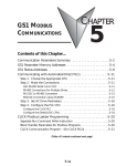
GS2 MODBUS
COMMUNICATIONS
CHAPTER
5
4
In This Chapter...
Communication Parameters Summary . . . . . . . . . .5–2
GS2 Parameter Memory Addresses . . . . . . . . . . . .5–4
GS2 Status Addresses . . . . . . . . . . . . . . . . . . . . . . .5–9
Communicating with DirectLogic PLCs . . . . . . . .5–12
Step 1: Choose the Appropriate CPU. . . . . . . . . . . . . . . . . . . . .5–12
Step 2: Make the Connections . . . . . . . . . . . . . . . . . . . . . . . . .5–12
Step 3: Set AC Drive Parameters . . . . . . . . . . . . . . . . . . . . . . . .5–14
Step 4: Configure the DirectLOGIC CPUs . . . . . . . . . . . . . . . . .5–14
DirectLOGIC Modbus Port Configuration . . . . . . . . . . . . . . . . .5–15
DirectLOGIC Modbus Ladder Programming . . . . . . . . . . . . . . .5–16
Communicating with Third-party Devices . . . . . .5–30
Data Format . . . . . . . . . . . . . . . . . . . . . . . . . . . . . . . . . . . . . . .5–31
Communication Protocol . . . . . . . . . . . . . . . . . . . . . . . . . . . . .5–32
Chapter 5: GS2 Modbus Communications
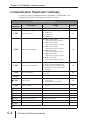
Communication Parameters Summary
A summary of the GS2 Communications Parameters is listed below. For a
complete listing of the GS2 Parameter, refer to CHAPTER 4.
Communications Parameters
GS2
Description
Parameter
Communication Address
P 9.00
Range
01 to 254
01
Transmission Speed
00: 4800 baud
01: 9600 baud
02: 19200 baud
03: 38400 baud
01
Communication Protocol
00: Modbus ASCII mode
7 data bits,no parity,2 stop bits
01: Modbus ASCII mode
7 data bits,even parity,1 stop bit
02: Modbus ASCII mode
7 data bits,odd parity,1 stop bit
03: Modbus RTU mode
8 data bits,no parity,2 stop bits
04: Modbus RTU mode
8 data bits,even parity,1 stop bit
05: Modbus RTU mode
8 data bits,odd parity,1 stop bit
00
P 9.03
Transmission Fault Treatment
00: Display fault and continue operating
01: Display fault and RAMP to stop
02: Display fault and COAST to stop
03: No fault displayed and continue
operating
00
P 9.04
Time Out Detection
00: Disable
01: Enable
00
P 9.05
Time Out Duration
0.1 to 60.0 seconds
0.5
P 9.01
P 9.02
쏆 P 9.07
P 9.08
쏆 P 9.11
쏆 P 9.12
쏆 P 9.13
쏆 P 9.14
쏆 P 9.15
쏆 P 9.16
쏆 P 9.17
Parameter Lock
Restore to Default
00: All parameters can be
set and read
01: All parameters are read-only
99: Restores all parameters to factory
defaults
00
00
Block Transfer Parameter 1
P0.00 to P8.01, P9.99
P 9.99
Block Transfer Parameter 2
P0.00 to P8.01, P9.99
P 9.99
Block Transfer Parameter 3
P0.00 to P8.01, P9.99
P 9.99
Block Transfer Parameter 4
P0.00 to P8.01, P9.99
P 9.99
Block Transfer Parameter 5
P0.00 to P8.01, P9.99
P 9.99
Block Transfer Parameter 6
P0.00 to P8.01, P9.99
P 9.99
Block Transfer Parameter 7
P0.00 to P8.01, P9.99
P 9.99
쏆 Parameter can be set during RUN Mode.
5–2
Default
GS2 Series AC Drive User Manual
Chapter 5: GS2 Modbus Communications
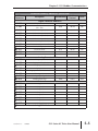
Communications Parameters (continued)
GS2
Parameter
쏆 P 9.18
쏆 P 9.19
쏆 P 9.20
쏆 P 9.21
쏆 P 9.22
쏆 P 9.23
쏆 P 9.24
쏆 P 9.25
쏆 P 9.26
Description
Range
Default
Block Transfer Parameter 8
P0.00 to P8.01, P9.99
P 9.99
Block Transfer Parameter 9
P0.00 to P8.01, P9.99
P 9.99
Block Transfer Parameter 10
P0.00 to P8.01, P9.99
P 9.99
Block Transfer Parameter 11
P0.00 to P8.01, P9.99
P 9.99
Block Transfer Parameter 12
P0.00 to P8.01, P9.99
P 9.99
Block Transfer Parameter 13
P0.00 to P8.01, P9.99
P 9.99
Block Transfer Parameter 14
P0.00 to P8.01, P9.99
P 9.99
Block Transfer Parameter 15
P0.00 to P8.01, P9.99
P 9.99
Serial Comm Speed Reference
0.0 to 400.0 Hz
00: Stop
01: Run
00: Forward
01: Reverse
00: No fault
01: External fault
00: No action
01: Fault Reset
00: Stop
01: Jog
#.##
01: GS1
02: GS2
03: GS3
00: GS2-20P5 (230V 1ph/3ph 0.5hp)
01: GS2-21P0 (230V 1ph/3ph 1hp)
02: GS2-22P0 (230V 1ph/3ph 2hp)
03: GS2-23P0 (230V 1ph/3ph 3hp)
04: GS2-25P0 (230V 3ph 5hp)
05: GS2-27P5 (230V 3ph 7.5hp)
06: Reserved
07: GS2-41P0 (460V 3ph 1hp)
08: GS2-42P0 (460V 3ph 2hp)
09: GS2-43P0 (460V 3ph 3hp)
10: GS2-45P0 (460V 3ph 5hp)
11: GS2-47P5 (460V 3ph 7.5hp)
12: GS2-4010 (460V 3ph 10hp)
13: GS2-10P2 (115V 1ph 0.25hp)
14: GS2-10P5 (115V 1ph 0.5hp)
15: GS2-11P0 (115V 1ph 1hp)
16~20: Reserved
21: GS2-51P0 (575V 3ph 1hp)
22: GS2-52P0 (575V 3ph 2hp)
23: GS2-53P0 (575V 3ph 3hp)
24: GS2-55P0 (575V 3ph 5hp)
25: GS2-57P5 (575V 3ph 7.5hp)
26: GS2-5010 (575V 3ph 10hp)
쏆 P 9.27
Serial Comm RUN Command
쏆 P 9.28
Serial Comm Direction Command
쏆 P 9.29
Serial Comm External Fault
쏆 P 9.30
Serial Comm Fault Reset
쏆 P 9.31
Serial Comm JOG Command
P 9.39
Firmware Version
P 9.41
GS Series Number
P 9.42
Manufacturer Model Information
60.0
00
00
00
00
00
#.##
##
##
쏆 Parameter can be set during RUN Mode.
1st Ed. Rev. C
12/2006
GS2 Series AC Drive User Manual
5–3
Chapter 5: GS2 Modbus Communications
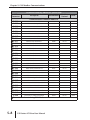
GS2 Parameter Memory Addresses
Parameter Memory Addresses
GS2
Parameter
Description
Hexadecimal
Modbus
Decimal
Octal
Motor Parameter Addresses
P 0.00
P 0.01
P 0.02
P 0.03
P 0.04
Motor Nameplate Voltage
0000
40001
0
Motor Nameplate Amps
0001
40002
1
Motor Base Frequency
0002
40003
2
Motor Base RPM
0003
40004
3
Motor Maximum RPM
0004
40005
4
Ramp Parameter Addresses
쏆
쏆
쏆
쏆
P 1.00
P 1.01
P 1.02
P 1.03
P 1.04
P 1.05
P 1.06
P 1.07
P 1.08
P 1.09
P 1.10
P 1.11
P 1.12
P 1.17
P 1.18
P 1.20
P 1.21
P 1.22
Stop Methods
0100
40257
400
Acceleration Time 1
0101
40258
401
Deceleration Time 1
0102
40259
402
Accel S-curve
0103
40260
403
Decel S-curve
0104
40261
404
Acceleration Time 2
0105
40262
405
Deceleration Time 2
0106
40263
406
Select method to use 2nd Accel/Decel
0107
40264
407
Accel 1 to Accel 2 frequency transition
0108
40265
410
Decel 2 to Decel 1frequency transition
0109
40266
411
Skip Frequency 1
010A
40267
412
Skip Frequency 2
010B
40268
413
Skip Frequency 3
010C
40269
414
Skip Frequency Band
0111
40274
421
DC Injection Current Level
0112
40275
422
DC Injection during Start-up
0114
40277
424
DC Injection during Stopping
0115
40278
425
Start-point for DC Injection
0116
40279
426
40513
1000
40514
1001
40515
1002
40517
1004
40518
1005
40519
1006
40520
1007
40521
1010
Volts/Hertz Parameter Addresses
Volts/Hertz Settings
0200
P 2.00
Slip Compensation
0201
쏆 P 2.01
Auto-torque Boost
0202
쏆 P 2.02
Mid-point Frequency
0204
P 2.04
Mid-point Voltage
0205
P 2.05
Min. Output Frequency
0206
P 2.06
Min. Output Voltage
0207
P 2.07
PWM Carrier Frequency
0208
P 2.08
쏆 Parameter can be set during RUN Mode.
5–4
GS2 Series AC Drive User Manual
Chapter 5: GS2 Modbus Communications
Parameter Memory Addresses (continued)
GS2
Parameter
Description
Hexadecimal
Modbus
Decimal
Octal
Digital Parameter Addresses
P 3.00
Source of Operation Command
0300
40769
1400
P 3.01
Multi-function Input Terminals
(DI1 - DI2)
0301
40770
1401
Multi-function Input (DI3)
0302
40771
1402
Multi-function Input (DI4)
0303
40772
1403
Multi-function Input (DI5)
0304
40773
1404
Multi-function Input (DI6)
0305
40774
1405
Multi-Function Output Terminal 1
030B
40780
1413
Multi-Function Output Terminal 2
030C
40781
1414
Desired Frequency
0310
40785
1420
Desired Current
0311
40786
1421
PID Deviation Level
0312
40787
1422
PID Deviation Time
0313
40788
1423
P 3.02
P 3.03
P 3.04
P 3.05
P 3.11
P 3.12
쏆 P 3.16
쏆 P 3.17
쏆 P 3.18
쏆 P 3.19
Analog Parameter Addresses
P 4.00
P 4.01
쏆 P 4.02
쏆 P 4.03
P 4.04
P 4.05
쏆 P 4.11
쏆 P 4.12
Source of Frequency Command
0400
41025
2000
Analog Input Offset Polarity
0401
41026
2001
Analog Input Offset
0402
41027
2002
Analog Input Gain
0403
41028
2003
Analog Input Reverse Motion Enable
0404
41029
2004
Loss of ACI Signal (4-20mA)
0405
41030
2005
Analog Output Signal
040B
41036
2013
Analog Output Gain
040C
41037
2014
Presets Parameter Addresses
쏆
쏆
쏆
쏆
쏆
쏆
쏆
쏆
P 5.00
P 5.01
P 5.02
P 5.03
P 5.04
P 5.05
P 5.06
P 5.07
Jog
0500
41281
2400
Multi-Speed 1
0501
41282
2401
Multi-Speed 2
0502
41283
2402
Multi-Speed 3
0503
41284
2403
Multi-Speed 4
0504
41285
2404
Multi-Speed 5
0505
41286
2405
Multi-Speed 6
0506
41287
2406
Multi-Speed 7
0507
41288
2407
쏆 Parameter can be set during RUN Mode.
1st Ed. Rev. C
12/2006
GS2 Series AC Drive User Manual
5–5
Chapter 5: GS2 Modbus Communications
Parameter Memory Addresses (continued)
GS2
Parameter
Description
Hexadecimal
Modbus
Decimal
Octal
Protection Parameter Addresses
P 6.00
P 6.01
P 6.02
P 6.03
P 6.04
P 6.05
P 6.06
P 6.07
P 6.08
P 6.09
P 6.10
P 6.11
P 6.12
P 6.13
P 6.14
P 6.15
P 6.16
P 6.31
P 6.32
P 6.33
P 6.34
P 6.35
P 6.36
Electronic Thermal Overload Relay
0600
41537
3000
Auto Restart after Fault
0601
41538
3001
Momentary Power Loss
0602
41539
3002
Reverse Operation Inhibit
0603
41540
3003
Auto Voltage Regulation
0604
41541
3004
Over-VoltageTrip Protection
0605
41542
3005
Auto Adjustable Accel/Decel
0606
41543
3006
Over-Torque Detection Mode
0607
41544
3007
Over-Torque Detection Level
0608
41545
3010
Over-Torque Detection Time
0609
41546
3011
060A
41547
3012
060B
41548
3013
Maximum Allowable Power Loss Time
060C
41549
3014
Base-Block Time for Speed Search
060D
41550
3015
Maximum Speed Search Current Level
060E
41551
3016
Upper Bound of Output Frequency
060F
41552
3017
Lower Bound of Output Frequency
0610
41553
3020
Present Fault Record
061F
41568
3037
Second Most Recent Fault Record
0620
41569
3040
Third Most Recent Fault Record
0621
41570
3041
Fourth Most Recent Fault Record
0622
41571
3042
Fifth Most Recent Fault Record
0623
41572
3043
Sixth Most Recent Fault Record
0624
41573
3044
Over-Current Stall Prevention
during Acceleration
Over-Current Stall Prevention
during Operation
쏆 Parameter can be set during RUN Mode.
5–6
GS2 Series AC Drive User Manual
Chapter 5: GS2 Modbus Communications
Parameter Memory Addresses (continued)
GS2
Parameter
Description
Hexadecimal
Modbus
Decimal
Octal
PID Parameter Addresses
P 7.00
P 7.01
P 7.02
쏆 P 7.10
쏆 P 7.11
쏆 P 7.12
쏆 P 7.13
쏆 P 7.14
쏆 P 7.15
쏆 P 7.16
쏆 P 7.17
쏆 P 7.20
쏆 P 7.21
쏆 P 7.22
P 7.23
P 7.24
P 7.25
P 7.26
P 7.27
Input Terminal for PID Feedback
0700
41793
3400
PV 100% Value
0701
41794
3401
PID Setpoint Source
0702
41795
3402
Keypad PID Setpoint
070A
41803
3412
PID Multi-setpoint 1
070B
41804
3413
PID Multi-setpoint 2
070C
41805
3414
PID Multi-setpoint 3
070D
41806
3415
PID Multi-setpoint 4
070E
41807
3416
PID Multi-setpoint 5
070F
41808
3417
PID Multi-setpoint 6
0710
41809
3420
PID Multi-setpoint 7
0711
41810
3421
Proportional Control
0714
41813
3424
Integral Control
0715
41814
3425
Derivative Control
0716
41815
3426
Upper Bound for Integral Control
0717
41816
3427
Derivative Filter Time Constant
0718
41817
3430
PID Output Frequency Limit
0719
41818
3431
Feedback Signal Detection Time
071A
41819
3432
PID Feedback Loss
071B
41820
3433
Display Parameter Addresses
쏆 P 8.00
쏆 P 8.01
User Defined Display Function
0800
42049
4000
Frequency Scale Factor
0801
42050
4001
쏆 Parameter can be set during RUN Mode.
1st Ed. Rev. C
12/2006
GS2 Series AC Drive User Manual
5–7
Chapter 5: GS2 Modbus Communications
Parameter Memory Addresses (continued)
GS2
Parameter
Description
Hexadecimal
Modbus
Decimal
Octal
Communications Parameter Addresses
P 9.00
P 9.01
P 9.02
P 9.03
P 9.04
P 9.05
쏆 P 9.07
P 9.08
쏆 P 9.11
쏆 P 9.12
쏆 P 9.13
쏆 P 9.14
쏆 P 9.15
쏆 P 9.16
쏆 P 9.17
쏆 P 9.18
쏆 P 9.19
쏆 P 9.20
쏆 P 9.21
쏆 P 9.22
쏆 P 9.23
쏆 P 9.24
쏆 P 9.25
쏆 P 9.26
쏆 P 9.27
쏆 P 9.28
쏆 P 9.29
쏆 P 9.30
쏆 P 9.31
P 9.41
P 9.42
Communication Address
0900
42305
4400
Transmission Speed
0901
42306
4401
Communication Protocol
0902
42307
4402
Transmission Fault Treatment
0903
42308
4403
Time Out Detection
0904
42309
4404
Time Out Duration
0905
42310
4405
Parameter Lock
0907
42312
4407
Restore to Default
0908
42313
4410
Block Transfer Parameter 1
090B
42316
4413
Block Transfer Parameter 2
090C
42317
4414
Block Transfer Parameter 3
090D
42318
4415
Block Transfer Parameter 4
090E
42319
4416
Block Transfer Parameter 5
090F
42320
4417
Block Transfer Parameter 6
0910
42321
4420
Block Transfer Parameter 7
0911
42322
4421
Block Transfer Parameter 8
0912
42323
4422
Block Transfer Parameter 9
0913
42324
4423
Block Transfer Parameter 10
0914
42325
4424
Block Transfer Parameter 11
0915
42326
4425
Block Transfer Parameter 12
0916
42327
4426
Block Transfer Parameter 13
0917
42328
4427
Block Transfer Parameter 14
0918
42329
4430
Block Transfer Parameter 15
0919
42330
4431
Serial Comm Speed Reference
091A
42331
4432
Serial Comm RUN Command
091B
42332
4433
Serial Comm Direction Command
091C
42333
4434
Serial Comm External Fault
091D
42334
4435
Serial Comm Fault Reset
091E
42335
4436
Serial Comm JOG Command
091F
42336
4437
GS Series Number
0929
42346
4451
Manufacturer Model Information
092A
42347
4452
쏆 Parameter can be set during RUN Mode.
5–8
GS2 Series AC Drive User Manual
Chapter 5: GS2 Modbus Communications
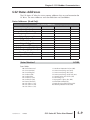
GS2 Status Addresses
The GS2 Series AC drive has status memory addresses that are used to monitor the
AC drive. The status addresses and value definitions are listed below.
Status Addresses (Read Only)
GS2 Status Addresses
Description
Status Monitor 1
Status Monitor 2
Frequency Command F
Output Frequency H
Output Current A
DC Bus Voltage d
Output Voltage U
Motor RPM
Scale Frequency (Low Word)
Scale Frequency (High Word)
Power Factor Angle
% Load
Firmware Version
Hexadecimal
Modbus Decimal
Octal
2100
48449
20400
2101
48450
20401
2102
48451
20402
2103
48452
20403
2104
48453
20404
2105
48454
20405
2106
48455
20406
2107
48456
20407
2108
48457
20410
2109
48458
20411
210A
48459
20412
210B
48460
20413
2110
48465
20420
Status Monitor 1
h2100
Error Codes:
00: No fault occurred
01: Over-current(oc)
02: Over-voltage(ov)
03: Overheat (oH)
04: Overload (oL)
05: Overload 1 (oL1)
06: Overload 2 (oL2)
07: External Fault (EF)
08: CPU failure 1 (cF1)
09: CPU failure 2 (cF2)
10: CPU failure 3 (cF3)
1st Ed. Rev. C
12/2006
11: Hardware Protection Failure (HPF)
12: Over-current during accel (ocA)
13: Over-current during decel (ocd)
14: Over-current during steady state (ocn)
15: Ground fault or fuse failure (GFF)
16: Low voltage (Lv)
17: Input power 3-phase loss (PHL)
18: External Base-Block (bb)
19: Auto adjust accel/decel failure (cFA)
20: Software protection code (codE)
GS2 Series AC Drive User Manual
5–9
Chapter 5: GS2 Modbus Communications
Status Monitor 2
h2101
GS2 Memory Data (binary)
0
0
0
0
0
0
0
0
0
1
0
0
0
1
0
10
48
20
40
81
8
76
16
32
38
0
1
2101
2
0
4
1
8
2
16
3
32
4
64
5
8
6
6
7
12
8
25
9
2
10
51
11
24
12
96
13
92
14
4
GS2 Memory Address
(hexadecimal) 15
Bits
Bit Values
(decimal)
Status Monitor 2 - Memory Address h2101
Address
Bit(s) Value
AC Drive Status
Bit(s) Binary (Decimal)
00 (0)
Drive operation stopped (STOP)
01 (1)
Run to Stop transition
10 (2)
Standby
11 (3)
Drive operation running (RUN)
1 (4)
JOG active
00 (0)
Rotational direction forward (FWD)
01 (8)
REV to FWD transition
10 (16)
FWD to REV transition
11 (24)
Rotational direction reverse (REV)
5
1 (32)
Source of frequency determined by serial comm interface (P4.00 = 5)
6
1 (64)
Source of frequency determined by AI terminal (P4.00 = 2, 3, or 4)
7
1 (128)
Source of operation determined by serial comm interface (P3.00 = 3 or 4)
8
1 (256)
Parameters have been locked (9-07 = 1)
9 to 15
N/A
0 and 1
2
3 and 4
Reserved
Frequency Command F (XXX.X)
h2102
Status location for the frequency setting of the AC drive.
Output Frequency H (XXX.X)
h2103
Status location for the actual operating frequency present at the T1, T2, and T3
terminal.
Output Current A
h2104
Status location for the output current present at the T1, T2, and T3 terminals.
DC-BUS Voltage d (XXX.X)
Status location for the DC Bus Voltage.
5–10
GS2 Series AC Drive User Manual
h2105
Chapter 5: GS2 Modbus Communications
Output Voltage U (XXX.X)
h2106
Status location for the output voltage present at the T1, T2, and T3 terminals.
Motor RPM
h2107
Status location for the present estimated speed of the motor.
Scale Frequency (Low word)
h2108
Status location for result of output frequency x P 8.01 (low word).
Scale Frequency (High word)
h2109
Status location for result of output frequency x P 8.01 (high word).
Power Factor Angle
h210A
Status location for the power factor angle.
% Load
h210B
Status location for the amount of load on the AC drive. (Output Current ÷ Drive
Rated Current) x 100.
Firmware Version
h2110
Status location for the firmware version of the AC drive.
1st Ed. Rev. C
12/2006
GS2 Series AC Drive User Manual
5–11
Chapter 5: GS2 Modbus Communications
Communicating with DirectLOGIC PLCs
The following steps explain how to connect to and communicate with the GS2
Series AC drives using DirectLOGIC PLCs.
Step 1: Choose the Appropriate CPU.
The GS2 Series AC drives will communicate with the following DirectLOGIC
CPUs using Modbus communications:
• DL05
• DL260
• DL06
• DL350
• DL250(-1)
• DL450
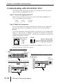
Step 2: Make the Connections
First you must decide what type of interface will work best for your application.
The GS2 Comm Port can accomodate an RS-232C or an RS-485 connection.
RS-232C
An RS-232C connection is somewhat limited. The maximum RS-232C network cable
length is 15 meters (50 feet). In addition, using the RS-232C interface will allow you
to connect an AC drive to only one PLC. For an RS-232C connection, set the GS2 DIP
switches SW2 and SW3 to RS232.
RJ-12 (6P4C) Serial Comm Port
6
1
RS-232C Interface
2: GND
3: RXD
4: TXD
5: +5V
RS485
SW3
Switches SW2 and SW3
must be set to RS232 for
an RS-232C connection.
SW2
RS232
Use the following wiring diagrams to connect your DirectLOGIC PLC to a GS2
Series AC drive with an RS-232C interface:
DL05: RS-232C Connection Wiring
DL05
PORT 2
1 0V
2 GND
3 RXD
4 TXD
4 TXD
3 RXD
GS2
Comm Port
DL350/DL450: RS-232C Connection Wiring
DL350 PORT 2
DL450 PORT 1
GS2
Comm Port
1
DL06/DL250/DL260: RS-232C Connection
Wiring
GS2
Comm Port
PORT 2
1
6
2 TXD
3 RXD
3 RXD
4 TXD
5 CTS
2 GND
4 RTS
15
5–12
7 GND
GS2 Series AC Drive User Manual
2 TXD
3 RXD
3 RXD
4 TXD
5 CTS
2 GND
4 RTS
7 GND
25
Chapter 5: GS2 Modbus Communications
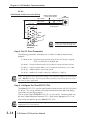
RS-232C to RS-485 Conversion
An RS-485 network cable can span up to 1000 meters (4000 feet). However, most
DirectLOGIC PLCs require an FA-ISOCON (RS-232C to RS-422/485 network adapter)
in order to make this type of connection. For an RS-485 connection, set the GS2 DIP
switches SW2 and SW3 to RS485.
RJ-12 (6P4C) Serial Comm Port
6
1
RS-485 Interface
2: GND
3: SG4: SG+
5: +5V
RS485
SW3
SW2
Switches SW2 and SW3
must be set to RS485 for
an RS-485 connection.
RS232
Use the following wiring diagrams to connect your DirectLOGIC PLC to a GS2
Series AC drive with an RS-485 interface:
Note: If an FA-ISOCON module is used in your connection, set the module
dipswitches S21 = ON; S22 - S27 = OFF; TERMINATE, BIAS, and DPX = ON. Refer to
FA-ISOCON manual for more detailed information.
DL05: RS-485 Connection Wiring
DL05
PORT 2
1 0V
2 5V
6 COM A
5 +5VDC
3 RXD
4 TXD
4 TXD
3 RXD
5 RTS
2 CTS
6 0V
1 COM A
C
+V
COM A
A
D
No connection
(for DL05)
TXD+
TXD-
4 SG+
RXD-
GS2
Comm Port
3 SG-
RXD+
2 COM
COM B
FA-ISOCON
DL250: RS-485 Connection Wiring
C
DL250
PORT 2
1
6
2 TXD
3 RXD
3 RXD
4 TXD
A
D
15
2 CTS
7 GND
6 GND
24VDC +
24VDC -
TXD+
TXD-
5 CTS
4 RTS
+V
COM A
4 SG+
RXD-
GS2
Comm Port
3 SG-
RXD+
2 COM
COM B
FA-ISOCON
DL350/DL450: RS-485 Connection Wiring
DL350 PORT 2
DL450 PORT 1
C
1
2 TXD
3 RXD
3 RXD
4 TXD
5 CTS
25
1st Ed. Rev. C
12/2006
4 RTS
2 CTS
7 GND
6 GND
A
D
+V
24VDC +
COM A
24VDC -
TXD+
TXDRXDRXD+
COM B
4 SG+
GS2
Comm Port
3 SG2 COM
FA-ISOCON
GS2 Series AC Drive User Manual
5–13
Chapter 5: GS2 Modbus Communications
RS-485
DL06/DL260: RS-485 Connection Wiring
Signal GND
RXD–
1
6
120⏲ Termination Resistor
at both ends of network
TXD+ / RXD+
4 SG +
TXD– / RXD–
3 SG 2 GND
Connect shield
to signal ground
GS2
Comm Port
11
RTS+
0V
TXD+ RXD+
RTS–
CTS+
10
5
15
DL06/DL260
CPU Port 2
CTS–
TXD–
Note: The Termination Resistor
is necessary only on large runs.
Step 3: Set AC Drive Parameters
The following parameters need to be set as shown in order to communicate
properly.
P 3.00: 03 or 04 – Operation Determined by RS-232C/RS-485 interface. Keypad
STOP is enabled (03) or disabled (04).
P 4.00: 05 – Frequency determined by RS-232/RS-485 communication interface
P 9.00: xx – Communication address 1-254 (unique for each device, see P 9.00)
P 9.01: 01 – 9600 baud data transmission speed
P 9.02: 05 – Modbus RTU mode <8 data bits, odd parity, 1 stop bit>
Note: The previous list of parameter settings is the minimum required to communicate
with a DirectLOGIC PLC. There may be other parameters that need to be set to meet
the needs of your application.
Step 4: Configure the DirectLOGIC CPUs
The DirectLOGIC CPUs must be configured to communicate with the GS2 Series
AC drives. This set up includes setting up the communication port and adding
instructions to your logic program.
The set up for all of the DirectLOGIC CPUs is very similar. However, there may
be some subtle differences between CPUs. Refer to the appropriate CPU User
Manual for the specifics on your DirectLOGIC CPU.
Note: For instructions on Modbus Configuration for your specific CPU, refer to the
appropriate CPU User Manual.
5–14
GS2 Series AC Drive User Manual
Chapter 5: GS2 Modbus Communications
DirectLOGIC Modbus Port Configuration
The following configuration example is specific to the DL250(-1) CPU. Refer to
the appropriate CPU User Manual for the specifics on your DirectLOGIC CPU.
• In DirectSOFT, choose the PLC menu, then Setup, then “Secondary Comm Port”.
• From the Port list box, choose “Port 2”.
• For the protocol, select “Modbus”.
• In the Timeout list box, select “800 ms”.
• Response Delay Time should be “0 ms”.
• The Station Number should be set to “1” to make the DL250(-1) CPU a Modbus
master.
Note: The DL250(-1) network instructions used in Master mode will access only slaves
1 to 90. Each slave must have a unique number.
• The Baud Rate should be set at “9600”.
• In the Stop Bits list box, choose “1”.
• In the Parity list box, choose “Odd”.
1st Ed. Rev. C
12/2006
GS2 Series AC Drive User Manual
5–15
Chapter 5: GS2 Modbus Communications
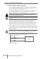
DirectLOGIC Modbus Ladder Programming
The set up for all of the DirectLOGIC CPUs is very similar. However, there may
be some subtle differences between CPUs. Refer to the appropriate CPU User
Manual for the specifics on your DirectLOGIC CPU.
The following ladder program shows some examples of how to control the GS2
AC drive through Modbus RTU. The drive should be setup and tested for
communications before it is connected to a load.
WARNING: A drive should never be connected to a load until any applicable
communication programs have been proven.
Note: This program is for illustration purposes only, and is not intended for a true
application.
In many drive applications, electromagnetic interference can sometimes cause
frequent, short duration communication errors. Unless the application
environment is perfect, an occasional communication error will occur. In order to
distinguish between these non-fatal transients and a genuine communication
failure, you may want to use the instructions as shown in Rungs 1 through 4.
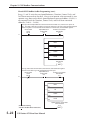
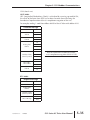
Rung 1 monitors the number of times that the PLC attempts to communicate with the
AC drive. When the PLC’s communication attempts are successful, SP116 will count
up, and SP117 will not count. Once the count reaches 9999, the counter will reset
and resume counting.
Note: SP116 and SP117 are special relays in the DirectLOGIC CPUs that monitor the
PLC’s communications. SP116 is on when Port 2 is communicating with another
device. SP117 is on when Port 2 has encountered a communication error.
This rung counts every time Port 2 is busy communicating.
DL250-1/260 Comm
SP116
1
Comm Transaction Count
CT0
(Continued next page)
5–16
GS2 Series AC Drive User Manual
CNT
Comm Transaction Count
CT0
K9999
Chapter 5: GS2 Modbus Communications
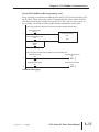
DirectLOGIC Modbus Ladder Programming (cont.)
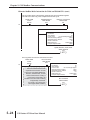
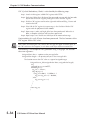
Rungs 2 through 4 monitor the number of times the PLC fails in communicating with
the AC drive. These instructions set the C0 control relay bit (to be used for alarm or
shut-down) based on the number of times the SP117 bit is active in one minute. In
this example, C0 will be set if the number of errors exceed 20 in one minute.
This rung counts every time Port 2 has an error communicating with the slave.
Comm Error Port 2
SP117
2
Comm Transaction Count
CT0
CNT
Comm Error Count
CT1
K20
_1Minute
SP3
This rung sets a control relay to indicate a communication error.
Comm Error Count
CT1
Comm Error Occurred
C0
External Comm Reset
X0
Comm Error Occurred
C0
3
4
( SET )
( RST )
(Continued next page)
1st Ed. Rev. C
12/2006
GS2 Series AC Drive User Manual
5–17
Chapter 5: GS2 Modbus Communications
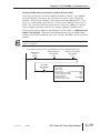
DirectLOGIC Modbus Ladder Programming (cont.)
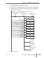
Rung 5 reads 12 of the status addresses of the GS2 AC drive. These instructions
read the values from the GS2 status addresses, 2100 to 210B, and places the
values into the PLC memory addresses, V2000 to V2013.
Notice the number in the RX box; V20400. 20400 is an octal number, as are all
address references in the DirectLOGIC PLCs. 20400 octal converted to hex is
2100, which is the first status address for the GS2 AC drive.
Note: Refer to your PLC User Manual for more specifics on Modbus addressing and
address conversions.
If not writing to the drive, this rung reads the first 12 status addresses of the drive.
DL250-1/260
Comm
SP116
Speed Reference
Write Enable
C10
Direction, Fault, Reset
Write Enable
C11
5
Run CMD
Write Enable
C12
LD
LD
LDA
RX
Kf201
K24
O2000
V20400
(Continued following “Alternate Modbus Read Instruction”)
5–18
GS2 Series AC Drive User Manual
Chapter 5: GS2 Modbus Communications
Alternate Modbus Read Instruction for DL06 and DL260 CPUs
The DL06 and DL260 CPUs offer “Modbus Read from Network” and “Modbus
Write to Network” instructions that are easier to use than are the “Read from
Network” and “Write to Network” instructions of the other DirectLOGIC CPUs.
Rung 5, as shown below, reads the first 12 of the status addresses of the GS2 AC
drive. This instruction reads the values from the GS2 status addresses, 2100 to
210B, and place the values into the PLC memory addresses V2000 to V2013.
The Start Slave Memory Address in the MRX box is 48449, which is a Modbus decimal
number (584/984 type). To convert 48449 decimal to hex, you first subtract 40001,
and then convert the remainder to (hex) 2100. H2100 is the address for the GS2 Status
Monitor.
Note: Refer to your PLC User Manual for more specifics on Modbus addressing and
address conversions.
If not writing to the drive, this rung reads the first 12 status addresses of the drive.
DL250-1/260
Comm
SP116
Speed Reference
Write Enable
C10
Direction, Fault, Reset
Write Enable
C11
5
Run CMD
Write Enable
C12
1st Ed. Rev. C
12/2006
MRX
Port Number:
K2
Slave Address:
K1
Function Code:
03 - Read Holding Register
Start Slave Memory Address:
48449
Start Master Memory Address:
V2000
Number of Elements:
K12
Modbus Data type:
584/984 Mode
Exception Response Buffer:
V5000
GS2 Series AC Drive User Manual
5–19
Chapter 5: GS2 Modbus Communications
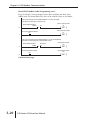
DirectLOGIC Modbus Ladder Programming (cont.)
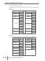
Rungs 6 through 9 show examples of how data read from the drive Status
Addresses to set Control Relay bits that can be used for alarm or shut-down.
6
This rung monitors the drive Status Monitor 1 for any drive fault,
and sets a control relay if a fault occurs.
Drive Fault Occurred
Drive Status Monitor 1
C1
V2000
K1
욷
Drive Fault Indication Reset
X1
7
8
Drive Fault Occurred
C1
( RST )
This rung monitors the drive Status Monitor 1 for an overload fault,
and sets a control relay if an overload fault occurs.
Overload Occurred
Drive Status Monitor 1
Overload
C2
V2000
K4
=
Overload Indication Reset
X2
9
(Continued next page)
5–20
( SET )
GS2 Series AC Drive User Manual
( SET )
Overload Occurred
C2
( RST )
Chapter 5: GS2 Modbus Communications
DirectLOGIC Modbus Ladder Programming (cont.)
Rung 10 monitors the Speed Reference, Direction, External Fault, and Fault Reset
Commands for changes. If there are any changes, then a control relay is set to
allow the Speed Reference to be written to the drive in the next rung. (This
control relay is also used in later rungs to enable writes for the other three listed
commands.)
The program monitors the commands for changes, and then writes to the drive
only when there is a change. This procedure promotes safe machine operation by
isolating the Run Command from the write block.
This rung monitors Speed Ref, Direction, External Fault, and Fault Reset for changes.
If any of them has changed, a write sequence is enabled to write the new values to the drive.
Speed Ref New
V3000
10
Direction New
V3002
Ext Fault New
V3003
Fault Reset New
V3004
=
=
=
=
Speed Ref Retain
V3010
Direction Retain
V3012
Ext Fault Retain
V3013
Fault Reset Retain
V3014
Run CMD
Write Enable
C12
Speed Ref
Write Enable
C10
Speed Ref
Write Enable
C10
( SET )
(Continued next page)
1st Ed. Rev. C
12/2006
GS2 Series AC Drive User Manual
5–21
Chapter 5: GS2 Modbus Communications
DirectLOGIC Modbus Ladder Programming (cont.)
Rungs 11 and 12 write the new Speed Reference, Direction, External Fault, and
Fault Reset commands to the drive. We use two separate write commands in two
separate rungs because the drive’s Speed Reference command address (O4432) is
not sequential with the Direction, External Fault, and Fault Reset command
addresses (O4434 ~ O4436).
This rung writes the Speed Reference to the drive when the Enable is on, and the comm port is not
busy. To be able to write all four registers, we have to write them in two write cycles because the Speed
Reference register is not consecutive with the Direction, External Fault, and Fault Reset registers.
Speed Reference
Direction, Fault, Reset
DL250-1/260
Write Enable
Write Enable
Comm
C10
C11
SP116
11
LD
LD
LDA
WX
Kf201
K2
O3000
V4432
Direction, Fault, Reset
Write Enable
C11
( SET )
This rung writes values to the Direction, External Fault, and Fault Reset registers.
This write occurs after rung 5 has completed the first write cycle.
Speed Reference
Direction, Fault, Reset
DL250-1/260
Write Enable
Write Enable
Comm
C10
C11
SP116
12
LD
LD
LDA
WX
(Continued following
“Alternate Modbus Write Instruction”)
5–22
GS2 Series AC Drive User Manual
Kf201
K6
O3002
V4434
Speed, Direction, Fault, Reset
Writes Finished
C13
( SET )
Chapter 5: GS2 Modbus Communications
Alternate Modbus Write Instruction for DL06 and DL260 CPUs
The DL06 and DL260 CPUs offer “Modbus Read from Network” and “Modbus
Write to Network” instructions that are easier to use than are the “Read from
Network” and “Write to Network” instructions of the other DirectLOGIC CPUs.
Rungs 11, 12, and 15 write the V3000 Speed Reference, V3002 Direction, V3003
External Fault, V3004 Fault Reset, and V3001 Run values to the corresponding drive
Modbus decimal addresses 42331, 42333, 42334, 42335, and 42332. In the first
MWX box, the slave start memory address is 42331, which is a Modbus decimal
number (584/984 type). To convert 42311 decimal to hex, you first subtract 40001,
and then convert the remainder to hex (91A). 91A is the address for the Serial Comm
Speed Reference.
Note: Refer to your PLC User Manual for more specifics on Modbus addressing and
address conversions.
This rung writes the Speed Reference to the drive when the Enable is on,
and the comm port is not busy. To be able to write all four registers, we have
to write them in two write cycles because the Speed Reference register is
not consecutive with the Direction, External Fault, and Fault Reset registers.
DL250-1/260
Comm
SP116
Speed Reference
Write Enable
C10
Direction, Fault, Reset
Write Enable
C11
11
MWX
Port Number:
K2
Slave Address:
K1
Function Code:
06 - Preset Single Register
Start Slave Memory Address:
42331
Start Master Memory Address:
V3000
Number of Elements:
n/a
Modbus Data type:
584/984 Mode
Exception Response Buffer:
V5001
Direction, Fault, Reset
Write Enable
C11
( SET )
(Continued next page)
1st Ed. Rev. C
12/2006
GS2 Series AC Drive User Manual
5–23
Chapter 5: GS2 Modbus Communications
Alternate Modbus Write Instruction for DL06 and DL260 CPUs (cont.)
This rung writes values to the Direction, External Fault, and Fault Reset registers.
This write occurs after rung 5 has completed the first write cycle.
DL250-1/260
Comm
SP116
Speed Reference
Write Enable
C10
Direction, Fault, Reset
Write Enable
C11
12
MWX
Port Number:
K2
Slave Address:
K1
Function Code:
16 - Preset Multiple Registers
Start Slave Memory Address:
42333
Start Master Memory Address:
V3002
Number of Elements:
K3
Modbus Data type:
584/984 Mode
Exception Response Buffer:
V5002
Speed, Direction, Fault, Reset
Writes Finished
C13
( SET )
This rung writes the new Run Command to the drive
DL250-1/260
Comm
SP116
15
Run Command
Write Enable
C12
MWX
The Run Command has its own
separate write instruction in order
to prevent a new Speed Reference,
Direction, External Fault, or Fault
Reset Command from causing a
previous Run Command to be
rewritten to the drive and overwritng
a keypad Stop Command.
(For P3.00 = 03; serial comm
with keypad STOP enabled.)
5–24
GS2 Series AC Drive User Manual
Port Number:
K2
Slave Address:
K1
Function Code:
06 - Preset Single Register
Start Slave Memory Address:
42332
Start Master Memory Address:
V2000
Number of Elements:
n/a
Modbus Data type:
584/984 Mode
Exception Response Buffer:
V5003
Run Command
Write Finished
C14
( SET )
Chapter 5: GS2 Modbus Communications
DirectLOGIC Modbus Ladder Programming (cont.)
Rung 13 loads the new Speed Reference, Direction, External Fault, and Fault Reset
Command values into the retained value registers, and resets the applicable Write
Enable control relays. Now the program is ready for the next command change
detection and write to the drive.
When both write cycles are completed, the retained values will be updated
with new values, and the write enable is reset.
Speed Reference
Write Enable
C10
Direction, Fault, Reset
Write Enable
C11
Speed, Direction, Fault, Reset
Writes Finished
C13
13
User Data Words:
V3000:
Load P9.26 Speed Ref Command
(with implied decimal place) here
Example: K150 for 15.0Hz
V3002:
Load P9.28 Direction Command here
0 = Forward
1 = Reverse
V3003:
Load P9.29 Ext Fault Command here
0 = No Action
1 = External Fault
V3004:
Load P9.30
Fault Reset Command here
0 = No Action
1 = Fault Reset
LD
Speed Ref New
V3000
Speed Ref Retain
V3010
OUT
LD
OUT
LD
Direction New
V3002
Direction Retain
V3012
Ext Fault New
V3003
OUT
Ext Fault Retain
V3013
LD
Ext Reset New
V3004
OUT
Ext Reset Retain
V3014
Speed Reference
Write Enable
C10
( RST )
Direction, Fault, Reset
Write Enable
C11
( RST )
Speed, Direction, Fault, Reset
Writes Finished
C13
( RST )
(Continued next page)
1st Ed. Rev. C
12/2006
GS2 Series AC Drive User Manual
5–25
Chapter 5: GS2 Modbus Communications
DirectLOGIC Modbus Ladder Programming (cont.)
Rungs 14 through 16 check for a Run Command change, write it to the drive,
store the new value in the program register, and reset the enable control relays.
14
This rung monitors the Run Command for changes. If a change is detected,
a write sequence is enabled to write the new value to the drive.
Speed Ref
Write Enable
Run CMD New
Run CMD Retain
C10
V3001
V3011
=
Run CMD
Write Enable
C12
Run CMD
Write Enable
C12
( SET )
This rung writes the new Run Command to the drive
DL250-1/260
Comm
SP116
15
Run Command
Write Enable
C12
LD
Kf201
LD
The Run Command has its own
separate write instruction in order
to prevent a new Speed Reference,
Direction, External Fault, or Fault
Reset Command from causing a
previous Run Command to be
rewritten to the drive and overwritng
a keypad Stop Command.
(For P3.00 = 03; serial comm
with keypad STOP enabled.)
K2
LDA
WX
O3001
V4433
Run Command
Write Finished
C14
( SET )
When the Run Command write is complete, this rung updates the Run Command
retained value with the new value, and resets the Write Enable.
Run Command
Write Enable
C12
Run Command
Write Finished
C14
16
LD
User Data Words:
V3001:
Load P9.27 Run Command here
0 = Stop
1 = Run
Run Command New
V3001
Run Command Retain
V3011
OUT
Run Command
Write Enable
C12
( RST )
Run Command
Write Finished
C14
(Continued next page)
5–26
GS2 Series AC Drive User Manual
( RST )
Chapter 5: GS2 Modbus Communications
DirectLOGIC Modbus Ladder Programming (cont.)
Rungs 17 through 26 show an example of a method of inputting command values
into the PLC.
This rung loads speed 1 into V3000.
LD: loads the constant value of 300 in BCD format;
BIN: converts from BCD to binary (HEX) format;
OUT: stores value in V3000 to instruct the drive to run at 30.0 Hz.
Speed Bit 1
30.0 Hz
X3
Speed Bit 2
60.0 Hz
X4
17
LD
K300
BIN
OUT
V3000
This rung loads speed 2 into V3000.
LD: loads the constant value of 600 in BCD format;
BIN: converts from BCD to binary (HEX) format;
OUT: stores value in V3000 to instruct the drive to run at 60.0 Hz.
Speed Bit 1
30.0 Hz
X3
18
Speed Bit 2
60.0 Hz
X4
LD
K600
BIN
OUT
V3000
This rung loads a value of 1 into V3001 for the drive Run Command
Run / Stop
X5
19
LD
OUT
K1
V3001
This rung loads a value of 0 into V3001 for the drive Stop Command
Run / Stop
X5
20
LD
OUT
K0
V3001
(Continued next page)
1st Ed. Rev. C
12/2006
GS2 Series AC Drive User Manual
5–27
Chapter 5: GS2 Modbus Communications
DirectLOGIC Modbus Ladder Programming (cont.)
This rung loads a value of 1 into V3002 for the drive Reverse Command
Reverse / Forward
X6
21
LD
OUT
K1
V3002
This rung loads a value of 0 into V3002 for the drive Forward Command
Reverse / Forward
X6
22
LD
OUT
K0
V3002
This rung loads a value of 1 into V3003 for the drive External Fault Command.
External Fault
X7
23
LD
OUT
K1
V3003
This rung loads a value of 0 into V3003 to remove the External Fault Command.
External Fault
X7
24
LD
OUT
K0
V3003
This rung loads a value of 1 into V3004 for the drive External Fault Reset Command
External Fault Reset
X8
25
LD
OUT
K1
V3004
This rung loads a value of 0 into V3004 to remove the External Fault Reset Command
External Fault Reset
X8
26
LD
OUT
27
5–28
GS2 Series AC Drive User Manual
K0
V3004
( END )
Chapter 5: GS2 Modbus Communications
DirectLOGIC Modbus Ladder Programming (cont.)
Separate Run Command Write Instruction
Why do we write the Run Command with a separate write instruction? If we write
the Run Command to the drive along with the Speed Reference, Direction, External
Fault, and Fault Reset Commands, we can keep the parameter addresses in sequence,
and we can update all five of the commands with one write instruction. This method
is valid only if we disable the drive’s keypad STOP button (P3.00 = 04).
Typically, the keypad STOP button will be enabled (P3.00 = 03), and we need to
prevent a change in one of the other commands from overriding a keypad Stop
Command by causing a previous Run Command to be rewritten to the drive. By
using a separate Run Command write instruction, only a deliberate Run Command
change by the program will run the drive again after a stop.
Block Transfer Parameters
For writing to any of the parameters from P0.00 to P8.01, a group of 15 block transfer
parameters (P9.11 to P9.25) is available in the GS2 AC drive. This sequential block of
parameters can be used to "group" various miscellaneous non-sequential parameters,
so that you can update the parameters in one programming write block instead of
having to use multiple WX commands.
For example: If you need to change the PID setpoint (P7.11), accel time (P1.01), and
multi-speed 1 (P5.01), this would typically take three different WX commands
because the parameters are non-sequential. However, by setting P9.11 to P7.11,
P9.12 to P1.01, and P9.13 to P5.01, the parameters become sequential, and can be
controlled using one WX command (LD Kf201, LD K6, LDA Oxxxx, WX V4413).
1st Ed. Rev. C
12/2006
GS2 Series AC Drive User Manual
5–29
Chapter 5: GS2 Modbus Communications
Communicating with Third-party Devices
First you must decide what type of interface will work best for your application.
The GS2 RJ-12 Serial Comm Port can accommodate an RS232C or an RS-485
connection.
RS-232C
An RS-232C connection is somewhat limited. The maximum network cable
length for an RS-232C connection is 15 meters (50 feet). In addition, using the
RS-232C interface will allow you to connect only one AC drive to one Modbus
device. For an RS-232C connection, set the GS2 DIP switches SW2 and SW3 to
RS232.
RJ-12 (6P4C) Serial Comm Port
6
1
RS-232C Interface
2: GND
3: RXD
4: TXD
5: +5V
RS485
SW3
SW2
Switches SW2 and SW3
must be set to RS232 for
an RS-232C connection.
RS232
RS-485
An RS-485 network cable can span up to 1000 meters (4000 feet). For an RS-485
connection, set the GS2 DIP switches SW2 and SW3 to RS485.
RJ-12 (6P4C) Serial Comm Port
6
1
RS-485 Interface
2: GND
3: SG4: SG+
5: +5V
RS485
SW3
SW2
Switches SW2 and SW3
must be set to RS485 for
an RS-485 connection.
RS232
The GS2 Series AC drive communication address is specified by P9.00. The third
party device then controls each AC drive according to its communication address.
The GS2 Series AC drive can be setup to communicate on standard Modbus
networks using the following transmission modes: ASCII or RTU. Using the
Communication Protocol parameter (P9.02), you can select the desired mode,
data bits, parity, and stop bits. The mode and serial parameters must be the same
for all devices on a Modbus network.
5–30
GS2 Series AC Drive User Manual
Chapter 5: GS2 Modbus Communications
Data Format
ASCII Mode: 10-bit character frame (For 7-bit character):
P9.02 = 00 (7 data bits, no parity, 2 stop bits)
Start
bit
0
1
2
3
4
5
6
Stop Stop
bit
bit
7-bit character
10-bit character frame
P9.02 = 01 (7 data bits, even parity, 1 stop bit)
Start
bit
0
1
2
3
4
5
6
Even Stop
parity bit
5
6
Odd Stop
parity bit
7-bit character
10-bit character frame
P9.02 = 02 (7 data bits, odd parity, 1 stop bit)
Start
bit
0
1
2
3
4
7-bit character
10-bit character frame
RTU Mode: 11-bit character frame (For 8-bit character):
P9.02 = 03 (8 data bits, no parity, 2 stop bit)
Start
bit
0
1
2
3
4
5
6
7
Stop Stop
bit
bit
6
7
Even Stop
parity bit
6
7
Odd Stop
parity bit
8-bit character
11-bit character frame
P9.02 = 04 (8 data bits, even parity, 1 stop bit)
Start
bit
0
1
2
3
4
5
8-bit character
11-bit character frame
P9.02 = 05 (8 data bits, odd parity, 1 stop bit)
Start
bit
0
1
2
3
4
5
8-bit character
11-bit character frame
1st Ed. Rev. C
12/2006
GS2 Series AC Drive User Manual
5–31
Chapter 5: GS2 Modbus Communications
Communication Protocol
ASCII Mode:
STX
Start Character: (3AH)
ADR 1
ADR 0
CMD 1
Communication Address: 8-bit address consists of 2 ASCII codes
CMD 0
DATA (n-1)
.......
Contents of data: n x 8-bit data consists of 2n ASCII codes. n ≤ 25
maximum of 50 ASCII codes
DATA 0
LRC CHK 1
LRC CHK 0
END 1
END-0
LRC check sum: 8-bit check sum consists of 2 ASCII codes
END characters: END 1 = CR (0DH), END 0 = LF (0AH)
RTU Mode:
START
A silent interval of more than 10 ms
ADR
Communication Address: 8-bit address
CMD
Command Code: 8-bit command
DATA (n-1)
Contents of data: n x 8-bit data, n ≤ 25
.......
DATA 0
CRC CHK Low
CRC CHK High
CRC check sum: 16-bit check sum consists of 2 8-bit characters
END
A silent interval of more than 10 ms
ADR (Communication Address)
Valid communication addresses are in the range of 0 to 254. Communication
address equals to 0 means broadcast to all AC drives, in which case the drives will
not reply any message to the master device.
For example, communication to AC drive with address 16 decimal:
ASCII mode: (ADR 1, ADR 0)='1','0' => '1'=31H, '0'=30H
RTU mode: (ADR)=10H
5–32
GS2 Series AC Drive User Manual
Chapter 5: GS2 Modbus Communications
CMD (Command code) and DATA (data characters)
The format of data characters depends on the command code. The available
command codes are described as followed: Command code: 03H, read N words.
The maximum value of N is 12. For example, reading continuous 2 words from
starting address 2102H of the AC drive with address 01H.
ASCII mode:
Command Message
Response Message
STX
':'
STX ':'
':'
ADR 1
ADR 0
'0'
ADR 1
ADR 0
'0'
CMD 1
CMD 0
'0'
CMD 1
CMD 0
'0'
Number of data
(Count by byte)
'0'
'1'
'3'
'2'
Starting data
address
'1'
'0'
'3'
'4'
'1'
Content of starting
data address
2102H
'2'
'0'
Number of data
(Count by word)
'1'
'7'
'7'
'0'
'0'
'0'
'0'
'2'
LRC CHK 1
LRC CHK 0
'D'
END 1
END 0
CR
Content data
address 2103H
'7'
'0'
'0'
'0'
LF
LRC CHK 1
LRC CHK 0
'7'
END 1
END 0
CR
'1'
LF
RTU mode:
Command Message
1st Ed. Rev. C
12/2006
Response Message
ADR
01H
ADR
01H
CMD
03H
CMD
03H
Starting data
address
21H
Number of data
(Count by byte)
04H
Number of data
(Count by word)
00H
Content of data
address 2102H
17H
CRC CHK Low
CRC CHK High
6FH
Content of data
address 2103H
00H
CRC CHK Low
CRC CHK High
FEH
02H
02H
F7H
'0'
70H
02H
5CH
GS2 Series AC Drive User Manual
5–33
Chapter 5: GS2 Modbus Communications
Command code: 06H, write 1 word
For example, writing 6000(1770H) to address 0100H of the AC drive with address
01H.
ASCII mode:
Command Message
Response Message
STX
':'
STX ':'
':'
ADR 1
ADR 0
'0'
ADR 1
ADR 0
'0'
CMD 1
CMD 0
'0'
CMD 1
CMD 0
'0'
'1'
'6'
'0'
'1'
'0'
Data Address
'1'
'6'
'0'
Data Address
'1'
'0'
'0'
'0'
'1'
'1'
'7'
'7'
Data Content
'0'
LRC CHK 1
LRC CHK 0
'7'
END 1
END 0
CR
'1'
LF
'7'
'7'
'0'
LRC CHK 1
LRC CHK 0
'7'
END 1
END 0
CR
'1'
LF
RTU mode:
This is an example of using function code 16 for writing to multiple registers.
Command Message
ADR
01H
ADR
01H
CMD
10H
CMD
10H
Starting data
address
20H
Starting data
address
20H
Number of data
(Count by word)
00H
CRC CHK Low
CRC CHK High
4AH
Number of registers
5–34
Response Message
00H
00H
02H
Byte count
04H
Content of data
address 2000H
00H
Content of data
address 2001H
02H
CRC CHK Low
CRC CHK High
CBH
02H
58H
34H
GS2 Series AC Drive User Manual
00H
02H
08H
Chapter 5: GS2 Modbus Communications
CHK (check sum)
ASCII Mode:
LRC (Longitudinal Redundancy Check) is calculated by summing up module 256,
the values of the bytes from ADR1 to last data character then calculating the
hexadecimal representation of the 2's-complement negation of the sum.
For example, reading 1 word from address 0401H of the AC drive with address 01H.
Command Message
STX
':'
ADR 1
ADR 0
'0'
CMD 1
CMD 0
'0'
'1'
'3'
'0'
Starting data
address
'4'
'0'
'1'
'0'
Number of data
(Count by word)
'0'
01H+03H+04H+01H+00H+01H=0AH;
the 2's complement negation of 0AH is F6H.
'0'
'1'
LRC CHK 1
LRC CHK 0
END 1
END 0
'F'
'6'
CR
LF
RTU Mode:
Response Message
1st Ed. Rev. C
ADR
01H
CMD
03H
Starting data
address
21H
Number of data
(Count by word)
00H
CRC CHK Low
CRC CHK High
6FH
12/2006
02H
02H
F7H
GS2 Series AC Drive User Manual
5–35
Chapter 5: GS2 Modbus Communications
CRC (Cyclical Redundancy Check) is calculated by the following steps:
Step 1: Load a 16-bit register (called CRC register) with FFFFH.
Step 2: Exclusive OR the first 8-bit byte of the command message with the low order
byte of the 16-bit CRC register, putting the result in the CRC register.
Step 3: Shift the CRC register one bit to the right with MSB zero filling. Extract and
examine the LSB.
Step 4: If the LSB of CRC register is 0, repeat step 3; else Exclusive OR the CRC
register with the polynomial value A001H.
Step 5: Repeat step 3 and 4 until eight shifts have been performed. When this is
done, a complete 8-bit byte will have been processed.
Step 6: Repeat steps 2 to 5 for the next 8-bit byte of the command message.
Continue doing this until all bytes have been processed. The final contents of the
CRC register are the CRC value.
Note: When transmitting the CRC value in the message, the upper and lower bytes of
the CRC value must be swapped, i.e. the lower order byte will be transmitted first.
The following is an example of CRC generation using C language. The function
takes two arguments:
Unsigned char* data ← a pointer to the message buffer
Unsigned char length ← the quantity of bytes in the message buffer
The function returns the CRC value as a type of unsigned integer.
Unsigned int crc_chk(unsigned char* data, unsigned char length){
int j;
unsigned int reg_crc=0xFFFF;
while(length--){
reg_crc ^= *data++;
for(j=0;j<8;j++){
if(reg_crc & 0x01){ /* LSB(b0)=1 */
reg_crc=(reg_crc>>1) ^ 0xA001;
}else{
reg_crc=reg_crc >>1;
}
}
}
return reg_crc;
}
5–36
GS2 Series AC Drive User Manual