1
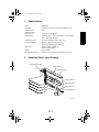
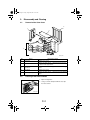
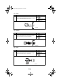
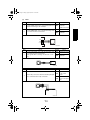
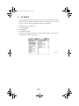
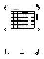
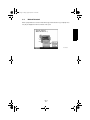
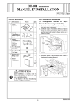
Cover(OP).fm Page 1 Friday, August 29, 2003 11:30 AM
MK-1
Service Manual
19971
MK-1TOC.fm Page i Friday, August 29, 2003 11:31 AM
CONTENTS
GENERAL
1. Specifications ...................................................................................................G-1
2. Revolving Parts Layout Drawing ......................................................................G-1
3. Electric Parts Layout Drawing ..........................................................................G-2
TEST MODES
1. Test Mode Operations ......................................................................................S-1
1-1. Entering the Tech. Rep. Mode .................................................................S-1
1-2. Entering Function Mode ...........................................................................S-1
1-3. Function Modes ........................................................................................S-2
(1) Mailbin Solenoid Drive Mode ...........................................................S-2
DIS/REASSEMBLY, ADJUSTMENT
1. Maintenance Schedule .....................................................................................D-1
2. Disassembly and Cleaning ...............................................................................D-2
2-1. Removal of the Outer Cover ....................................................................D-2
2-2. Cleaning of the Roller and Roll ................................................................D-2
TROUBLESHOOTING
1. Introduction ......................................................................................................T-1
1-1. Electrical Components Check Procedure ................................................T-1
(1) Sensor .............................................................................................T-1
(2) Switch .............................................................................................T-2
(3) Solenoid ...........................................................................................T-2
(4) Clutch .............................................................................................T-2
(5) Motor .............................................................................................T-3
2. I/O CHECK .......................................................................................................T-4
2-1. I/O Check List ...........................................................................................T-5
3. Misfeed Detection/Troubleshooting Procedures ..............................................T-6
3-1. Initial Checks ............................................................................................T-6
3-2. Misfeed-Detecting Sensor Layout ............................................................T-6
3-3. Misfeed Detected .....................................................................................T-7
3-4. Misfeed Detection Timing/Troubleshooting Procedures ..........................T-8
(1) Transport Section Misfeed ...............................................................T-8
i
Cover_G.fm Page 1 Friday, August 29, 2003 11:31 AM
GENERAL
G.fm Page 1 Friday, August 29, 2003 11:32 AM
1.
Specifications
Name
: Mail Bin Kit
Installation
: Install at the top section of the Finisher Elevator Tray.
Number of Bins
: 4 bins
Number of Sheets
Stored per Bin
:
Storable Paper
: Plain paper 15lb. to 24lb. (56 to 90 g/m2), recycled paper
125 sheets 21.3lb. (80 g/m2)
16lb. to 24lb. (60 to 90 g/m2)
Storable Paper Size
: A5L, B5C, and A4C (5-1/2L, 8-1/2 x 11C)
Power Requirements
: DC 24 V (supplied from the Finisher)
DC 5 V (generated inside the Mail Bin)
Dimensions
: 624(W) x 390(H) x 503(D) mm
24-1/2 x 15-1/4 x 19-3/4
Weight
: 8 kg (17-3/4 lbs)
Operating Environment
: Conforms to the operating environment of the copier.
2.
Revolving Parts Layout Drawing
Transport Motor (M1)
Paper Exit Roll 4
Paper Exit Roll 3
Transport Roller 2
Paper Exit Roll 2
Paper Exit Roll 1
Transport Roller 1
4510G502AA
G-1
G.fm Page 2 Friday, August 29, 2003 11:32 AM
3.
Electric Parts Layout Drawing
SL3-MK
PC11-MK
M1-MK
PC6-MK
PC8-MK
SL2-MK
PC4-MK
PC7-MK
PWB-A MK
PC3-MK
PC9-MK
PC2-MK
SL1-MK
PC1-MK
PC5-MK
PC10-MK
4510G501AA
Symbol
Name
Symbol
Name
PWB-A MK
M1-MK
SL1-MK
SL2-MK
SL3-MK
PC1-MK
PC2-MK
PC3-MK
Control Board
Transport Motor
Bin Switching Solenoid 1
Bin Switching Solenoid 2
Bin Switching Solenoid 3
Paper Detection Sensor 1
Paper Detection Sensor 2
Paper Detection Sensor 3
PC4-MK
PC5-MK
PC6-MK
PC7-MK
PC8-MK
PC9-MK
PC10-MK
PC11-MK
Paper Detection Sensor 4
Bin 1 Paper Full Detecting Sensor
Bin 2 Paper Full Detecting Sensor
Bin 3 Paper Full Detecting Sensor
Bin 4 Paper Full Detecting Sensor
Upper Transport Sensor
Lower Transport Sensor
Cover Open/Close Sensor
G-2
Cover_S.fm Page 1 Friday, August 29, 2003 11:32 AM
TEST MODES
S.fm Page 1 Tuesday, September 2, 2003 9:07 AM
1.
Test Mode Operations
• The Test Mode is performed from the copier’s Tech. Rep. Mode.
1-1.
Entering the Tech. Rep. Mode
1. Press the Utility key.
2. Touch [Total Check].
3. Press the following keys in order: Stop → 0 → 0
→ Stop → 0 → 1.
NOTE
• Be sure to keep the display procedure for the Tech.
Rep. Mode from any unauthorized persons not
involved with service operations.
4344S504CA
1-2.
Entering Function Mode
1. Display the Tech. Rep. Mode screen.
2. Touch [Function].
4344S504CA
3. Touch [FC].
4349S501CA
4. Touch [12].
4349S502CA
S-1
S.fm Page 2 Friday, August 29, 2003 11:33 AM
1-3.
Function Modes
The following item is available under “FC” in the Function Mode.
• 12: Mailbin solenoid drive mode
(1)
Mailbin Solenoid Drive Mode
• Bin Entrance Switching Solenoids 1, 2 and 3 switch, in order, at the predetermined times.
→Bin Entrance Switching Solenoid 1 (SL1-MK) activates for the predetermined time.
→Bin Entrance Switching Solenoid 2 (SL2-MK) activates for the predetermined time.
→Bin Entrance Switching Solenoid 3 (SL3-MK) activates for the predetermined time.
→All Bin Entrance Switching Solenoids deactivate.
→The operation is finished.
S-2
Cover_D.fm Page 1 Friday, August 29, 2003 11:34 AM
DIS/REASSEMBLY,
ADJUSTMENT
D.fm Page 1 Friday, August 29, 2003 11:41 AM
1.
Maintenance Schedule
• To ensure that the copier produces good copies and to extend its service life, it is recommended that the maintenance jobs described in this schedule be carried out as
instructed.
PM Parts
Job
Clean
Replace
Roller
300k
—
Roll
300k
—
Item Used for Cleaning
Alcohol and soft cloth
Qty
Ref. Page
2
☞ D-2
6
☞ D-2
NOTES
• K = 1,000 copies
• The contents of this maintenance schedule are subject to change without notice.
• For part numbers, see Parts Manual and Parts Modification Notice.
D-1
D.fm Page 2 Friday, August 29, 2003 11:41 AM
2.
Disassembly and Cleaning
2-1.
Removal of the Outer Cover
3
1
2
4
5
4510D501AA
No.
Name
Removal Procedure
1
Rear Cover
Remove one screw.
2
Upper Cover
Remove the Rear Cover. → Remove the Front Cover.
→ Remove the Upper Cover.
3
Right Cover
Remove one screw and stopper. → Remove the Right
Cover.
4
Front Cover
Remove one screw.
5
Paper Output Tray
Remove the Rear Cover. → Remove the Paper Output
Trays.
2-2.
Cleaning of the Roller and Roll
1. Open the Right Door.
2. Using a soft cloth dampened with alcohol, wipe
the roller and roll.
4510D001AA
D-2
Cover_T.fm Page 1 Friday, August 29, 2003 11:42 AM
TROUBLESHOOTING
T.fm Page 1 Friday, August 29, 2003 11:42 AM
1.
Introduction
• Information required for troubleshooting and steps that must be performed are described
in this chapter.
1-1.
Electrical Components Check Procedure
• If a paper misfeed or malfunction occurs, perform the following operation to check the
condition of the electrical components.
(1)
Sensor
Step
1
Check
Result
Does the input signal of the control board change
when the sensor light is interrupted? (H → L, L → H)
DC5V
4025T520AA
4025T521AA
T-1
Action
NO
Replace the sensor.
YES
Replace the control board.
T.fm Page 2 Friday, August 29, 2003 11:42 AM
(2)
Switch
Step
Check
Result
1
Does the input signal (NO) of the control board change
from L to H when the switch is turned on?
Action
NO
Replace the
switch.
YES
Replace the control board.
NO
Not Use
COM
4025T523AB
(3)
Solenoid
Step
1
Check
Result
Does the output signal of the control board change
from H to L when the solenoid is activated?
1
2
2
1
Action
NO
Replace the control board.
YES
Replace the solenoid.
1
2
4025T522AA
(4)
Step
1
Clutch
Check
Result
Does the output signal of the control board change
from H to L when the clutch is activated?
NO
YES
Replace the
clutch.
4025T528AA
T-2
Action
Replace the control board.
T.fm Page 3 Friday, August 29, 2003 11:42 AM
(5)
Motor
Step
Check
Result
Action
1
Does the LOCK signal of the control board switch to H
when the machine goes into standby?
NO
Replace the control board.
Replace the motor.
2
Does the REM signal of the control board change from
H to L when the motor is turned on?
YES Replace the motor.
NO
Replace the control board.
GND 1
REM 2
3
LOCK
4025T526AA
Step
Check
Result
1
Does the input signal of the control board change from
H to L when the motor is turned on?
(Input signals differ according to the direction of rotation)
Action
YES Replace the motor.
NO
Replace the control board.
4025T525AA
Step
1
Check
Result
Are the relay connector of the motor and the print jack
of the control board correctly connected?
NO
4025T527AA
T-3
Action
Replace the motor
YES or the control
board.
Connect the connector or the print
jack.
T.fm Page 4 Friday, August 29, 2003 11:42 AM
2.
I/O CHECK
• For an easy and safe operation check of the sensors, the sensor input data is checked
when the copier is in standby (including when a misfeed or a malfunction occurs or when
a part is not correctly closed) to determine if signals are properly input.
1. Display the Tech. Rep. Mode screen.
2. Touch [I/O CHECK].
3. Touch [Finisher].
4. Touch [Next] three times.
5. Using a sheet of paper, activate the sensor and check the display in the Touch Panel.
(Paper present: 1; Paper not present: 0)
4510T501CA
T-4
T.fm Page 5 Friday, August 29, 2003 11:42 AM
2-1.
Symbol
PC10MK
I/O Check List
Panel Display
Mailbin Transport1
PC9-MK Mailbin Transport2
PC11MK
Mailbin 1 Full
Detection
Mailbin 2 Empty
PC2-MK
Detection
PC6-MK
Mailbin 2 Full
Detection
Mailbin 3 Empty
PC3-MK
Detection
PC7-MK
Mailbin 3 Full
Detection
Mailbin 4 Empty
PC4-MK
Detection
PC8-MK
Mailbin 4 Full
Detection
Input Board
CN/PJ
No.
1
0
Lower Transport Sensor
Paper
present
Paper not
present
CN102A MK-8
Upper Transport Sensor
Paper
present
Paper not
present
CN101A MK-8
Mailbin Door Open/ Cover Open/Close SenClose Sensor
sor
Mailbin 1 Empty
PC1-MK
Detection
PC5-MK
Operation Characteristics/
Panel Display
Parts/Signal Name
Paper Detecting Sensor
1
Mailbin 1 Paper Full
Detecting Sensor
Paper Detecting Sensor
2
Mailbin 2 Paper Full
Detecting Sensor
Paper Detecting Sensor
3
Mailbin 3 Paper Full
Detecting Sensor
Paper Detecting Sensor
4
Mailbin 4 Paper Full
Detecting Sensor
Open
Closed
CN100A MK-2
Paper not
present
Paper
present
CN102A MK-11
Blocked
Unblocked
Paper not
present
Paper
present
CN102A MK-5
Control
Board
(PWB-A MK)
CN102A MK-2
Blocked
Unblocked
CN101A MK-5
Paper not
present
Paper
present
CN101A MK-2
Blocked
Unblocked
CN100A MK-11
Paper not
present
Paper
present
CN100A MK-8
Blocked
Unblocked
CN100A MK-5
T-5
T.fm Page 6 Friday, August 29, 2003 11:42 AM
3.
3-1.
Misfeed Detection/Troubleshooting Procedures
Initial Checks
• When a paper misfeed occurs, first perform the following initial checks.
Check Item
Action
Does paper meet product specifications?
Replace paper.
Is the paper curled, wavy, or damp?
Replace paper.
Instruct the user on the correct paper
storage procedures.
Is a foreign object present along the paper path, Remove object or replace the damaged
or is the paper path deformed or worn?
paper path.
Are the Paper Separator Fingers dirty,
deformed, or worn?
Clean or replace the defective Paper
Separator Finger.
Are rolls/rollers dirty, deformed, or worn?
Clean or replace the defective roll/roller.
Are the Edge Guide and Trailing Edge Stop at
Set as necessary.
the correct position to accommodate the paper?
Are the actuators operating correctly?
3-2.
Correct or replace the defective actuator.
Misfeed-Detecting Sensor Layout
Upper Transport Sensor (PC9-MK)
Lower Transport Sensor (PC10-MK)
Transport Sensor (PC5-FN)
4510T502AA
T-6
T.fm Page 7 Friday, August 29, 2003 11:42 AM
3-3.
Misfeed Detected
When a paper misfeed occurs, the misfeed message, misfeed location (⊗), and paper location (❍) are displayed on the Touch Panel of the copier.
4510T503CA
T-7
T.fm Page 8 Friday, August 29, 2003 11:42 AM
3-4.
(1)
Misfeed Detection Timing/Troubleshooting Procedures
Transport Section Misfeed
<Detection Timing>
Type
Description
Transport Section misfeed detection
The Lower Transport Sensor (PC10-MK) is not blocked even
after the set period of time has elapsed after the Transport Sensor (PC5-FN) is unblocked by the paper.
The Upper Transport Sensor (PC9-MK) is not blocked even after
the set period of time has elapsed after the Lower Transport Sensor (PC10-MK) is blocked by the paper.
The Lower Transport Sensor (PC10-MK) is blocked when the
Power Switch is set to ON, a door or cover is opened and closed,
or a misfeed or malfunction is reset.
Detection of paper
remaining in the TransThe Upper Transport Sensor (PC9-MK) is blocked when the
port Section
Power Switch is set to ON, a door or cover is opened and closed,
or a misfeed or malfunction is reset.
Action
Relevant Electrical Components
Control Board (PWB-A)
Transport Sensor (PC5-FN)
Lower Transport Sensor (PC10-MK)
Upper Transport Sensor (PC9-MK)
WIRING DIAGRAM
Step
Operations
Ref.
Page
Control signal
Location
(Electrical
Components)
1
Initial checks
☞ T-6
—
—
2
PC5-FN sensor check
☞ T-1
PWB-A FN PJ20A FN-9
E-7
3
PC10-MK sensor check
☞ T-1 PWB-A MK CN102A MK-8
4
PC9-MK sensor check
☞ T-1 PWB-A MK CN101A MK-8
5
PWB-A MK replacement
—
T-8
—
D-7
B-7
E-4