1
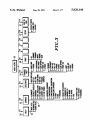
United States Patent [191
[11]
[45]
Shirley, Jr. et al.
REPLACEMENT/PROGRAMMING DEVICE
Users manual for programming the Mostar NVR (Man
ual No. 68P80100W88-O, published in 1985.
HT6OO Programmer/Tuner User’s Manual (Manual
[75] Inventors: ‘Thomas F. Shirley, Jr., Fort Worth;
Jack B. Butler, Bedford, both of Tex.
[73] Assignee: Motorola, Inc., Schaumburg, Ill.
[21] Appl. No.: 175,361
No. 68P81045C55-2.
SMARTNET Standalone Field Programmer Model
T5124A (Programming Information Guide 68P-811
l7El1-0, published in 1985.
Systems 9000 Conventional Radio Programmer Opera
tor’s Manual (Manual No. 68-80309B24-0, published in
1986.
Systems 9000 Conventional Control Head Programmer
Operator’s Manual, (Manual No. 68-80309B25-O, dated
Mar. 30, 1988
[51]
Int. Cl.5 ............................................. .. H04B 1/16
[52]
US. Cl. .................................. .. 455/186; 455/ 185;
[58]
Field of Search .... .; ........... .. 455/76, 77, 183, 185,
.
455/151
455/186, 151; 364/2219, 222.81, 227.3, 468,
May 15, 1986).
919.2
[56]
Systems 9000 Trunked Control Head Programmer Op
erator’s Manual (Operator’s Manual No. 68-80309B
References Cited
26-0, dated May 15, 1986.
U.S. PATENT DOCUMENTS
4,525,865
6/1985
4,688,261
8/1987 Killoway et a1.
4/1988
455/186
Soderberg et al. .... ..
4,771,399 9/1988 Snowden et al.
4,792,986 12/1988
“The up: The Key to an Advanced Frequency Synthe
sized HF SSB Amateur Radio Transceiver”; IEE
Transactions on Consumer Electronics; vol. CE-26;
Mears ................................ .. 455/186
4,739,486
May 28, 1991
EEPROM Programmer (Instruction Manual No.
68PO6088T60-0, published in 1984.
[54] RADIO COMPONENT
[22] Filed:
5,020,144
Patent Number:
Date of Patent:
364/464
Aug. 1980; pp. 234-246, class 455/76.
Primary Examiner-Douglas W. Olms
Assistant Examiner-Ralph Smith
455/186
Garner et al. ..................... .. 455/186
OTHER PUBLICATIONS
Attorney, Agent, or Firm-Steven G. Parmelee
The MC Micro Field Programmer Handbook, dated
1985 by Motorola Gmbl-I Taunusstein.
Systems 9000 Trunked Radio Programmer, dated 1986
[57]
ABSTRACT
A programming station for use in programming and
servicing two-way radios that include replaceable hard
ware elements. Both user-only and programming sta
tion-assisted steps are simultaneously displayed in a
predetermined order. The steps may only be accom
by Motorola, Inc.
Systems 9000 Conventional Options Programmer,
dated 1985, Motorola, Inc.
Systems 9000 Conventional 64 Mode Radio and Con
trol Head Programmer, dated Nov. 12, 1985.
Systems 9000 Conventional 32 Mode Radio and Con
trol Head Programmer, dated Nov. 12, 1985.
plished in a fixed. allowed order.
16 Claims, 7 Drawing Sheets
18
19
‘PRINTER
16
/
"a
llllllllllllll
RIB
“m
.
1a
"
._
12
+ P0 FER
- SOURCE‘
11
l
EL 11111111]
VOLUME
12mm]
L___]
[313G]
[BEBE]
[DEJE]
17
US. Patent
May 28, 1991
Sheet 1 of 7
5,020,144
D
I8
40
19
o
O
PRINTER
/
14\\
I
IIIIIIIIIIIEI
RIB
13
I6
[I g
u‘
17
I‘
3<
12
+- SOURCE
POWER ,
11
L
[jumps
mmumcnan%%%
DJ
1mm
VOLUME
19
[E91
[M113
FIG. 1
FIG.2
1/ 21
20
._
/ 23
7
'
7
3 1 82
1/ 22
lsascFFiucnon m F1-F10. '
w
I
MAIN MENU
- HELP
- SERVICE: ALIGNMENT, SERVICE AIDS AND BOARD REPLACEMENTS
G ET SAVE
PROGRAM CODEPLUG DATA FROMRO DISK/CODEPLUC
CHANGE/VIEW CREATE RADIO CODEPLUG
PRINT CODEP UC DATA
1
- SETUP CGIPUTER CONFIGURATION
F10- EXIT RADIO SERVICE SOFTWAREl RETURN TO DOS
F1
F2
F3
F4
F5
F6
F7
F8
F9
HELP SERVICE SAVE
GET CHANGE
PRINT
VIEW
(
F10
SETUP TOEXIT
DOS
L(1D 1987 MOTOROLA, INC.
J
24
US. Patent
May 28, 1991
Sheet 2 of 7
m..UFW
5,020,144
US. Patent
May 28, 1991
Sheet 4 of 7
5,020,144
FIG. 4
21
f
32
1/
__
FsPEcrRA' MODEL: omewaw
1/ 22 /23
sum ruucnou KEY FI-FIO. ’ /S
sm
7
1
_
[:l
SERVICE MENU
1
F1 - HELP
F'Z — AUGNNIENT: TRANSMITTER AND RECEIVER
g — ADVANCED ALIGNMENT PROCEDURES FOR BOARD REPAIR ONLY
‘I?’ — BOARD REPLACEMENT PROCEDURES
F8 — SERVICE AIDS RID TROUBLE SHOOTING AIDS
F9 -
m- EXIT/RETURN TO MAIN MENu
FI
F2
F3 F4
F5
F6
F7
HEIP ALIGNMENT ADVANCED
BOARD
F8
F9
SERVICE
ALIGNMENT REPLACEMENT /
LL
F10
EXIT
AIDS
(3) 1987 MOTOROLA, INC.
J
24
.
1/ 21
5g
23
_
/ 22
GsPEcmA
sRvcA- REPAIR
I MODEI.‘ D37KGA5JB9AK IsELEcr
7
FUNCTION KEY FI-FIII '
BOARD REPLACEMENT / REPAIR MENU
F1 - HELP
/1
7
[:l
/
'
F3 - coMMAND m0 AND
OR MICROPROCESSOR REPAIR / REPLACEMENT
g - MEMORY BOARD REPIA EMENT
F6 - POWER AMPunER REPAIR
REPLACEMENT
Fl-RFBOARDREPAIR/REP
EMENT
F8 _
F9 — VCO BOARD REPAIR
REPLACEMENT
FID- EXIT / RETIRN TO ERVICE MENU
HELP
COMMAND MEMORY
BOARD BOARD
PA
RF
BOARD BOARD
L© 1987 MOTOROLA, INC.
vco EXIT
soARo
J
\
24
©©©k
US. Patent
May 28, 1991
Sheet 6 of 7
5,020,144
FIG.9
,2:
/ 22
frwm
Wham
‘m
m
u.
m
m
um
n
2m
m."
mwm
"mm
Mm
@mmm
WWmo
5. mm
W
mm
W
W...
mmmm
WWW
Hmmm.
HW.
1%
mm
nmmm
wwm
swam
mmw
mmmm
W
m.
W
PW
m
D7T
[QHH
1.234.:1.1
n
HSmr
.MRC1.-HERFM2
mm
Mmnm
aum
wG11km?/l\\m
m
W
m
D.
.FF.. E
mm
0
Lm
W
H
W
m
m
H
M
. /2/7
2y
J
/U©E©
W
MWSPBW
u\.
j
US. Patent
May 28, 1991
Sheet 7 of 7
5,020,144
FIG. 1 1
23
1/ 21
/ 22
OSPECTRA ' noon.- osvxcmaw lsascr ruucnou m n-Fw '
save REPAIR: vco so
vco mo REPLACEMENT PROCEDURE
WE+
7i
F2
cow
scr
F5
DEV
sEr
F4
F5
F6
F7
F8
/
F9
ice) 1987 MOTOROLA, mc.
F10
cxn
J
\
-
If
i
[I]
REPLACE VCO BOARD PER SERVICE MANUAL
PRESS F2 T0 AUGN VCO COMPENSKTION QAUBRATION.
PRES F3 TO AUGN V00 DEVIATION.
BOPRD REPlACEMENT PROCEDURE l5 COMPLETE
PRESS F10 TWICE TO RETURN TO SERVICE MENU.
r1
new
k’
/
5,020,144
1
2
BRIEF DESCRIPTION OF THE DRAWINGS
FIG. 1 comprises a block diagram depiction of the
RADIO COMPONENT
REPLACEMENT/PROGRAMMING DEVICE
invention as coupled to a two-way radio;
FIG. 2 comprises a depiction of a main menu as pres
MICROFICHE APPENDIX
This speci?cation includes a micro?che appendix
comprising 7 micro?che and 643 frames.
ented at the programming station;
FIG. 3 comprises a diagrammatic representation of
the functional capabilities of the programming station;
FIG. 4 comprises a depiction of a service menu as
COPYRIGHT INFORMATION
10 presented at the programming station;
A portion of the disclosure of this patent document
FIG. 5 comprises a diagrammatic representation of
contains material that is subject to copyright protection.
the functional capabilities available at the programming
The copyright owner has no objection to the facsimile
reproduction by anyone of the patent document or the
patent disclosure, as it appears in the Patent and Trade
mark Of?ce patent file or records, but otherwise re
serves all copyright'rights whatsoever.
station from the service menu;
FIG. 6 comprises a depiction of a board replacement
/repair menu as presented at the programming station;
FIG. 7 comprises a depiction of a command board or
microprocessor replacement procedure menu as pres
ented at the programming station;
TECHNICAL FIELD
FIG. 8 comprises a depiction of a memory board
This invention relates generally to the programming 20 replacement procedure menu as presented at the pro
and servicing of two-way radios.
gramming station;
FIG. 9 comprises a power ampli?er replacement
BACKGROUND ART
procedure menu as presented at the programming sta
Two-way radios are becoming increasingly sophisti
tion;
cated. Many such radios now realize many operating
functions and features through provision of an on-board
microprocessor. For example, some models of the Spec
tra land mobile radio, manufactured by Motorola, Inc.,
do not include any internal adjustable components such
as potentiometers or coils. Instead, all RF and signalling
parameters are controlled by an on-board microproces
FIG. 10 comprises an RF board replacement proce
dure menu as presented at the programming station; and
FIG. 11 comprises a VCO board replacement proce
dure menu as presented at the programming station.
BEST MODE FOR CARRYING OUT THE
INVENTION
Referring now to FIG. 1, the programming station,
sor.
These increasingly sophisticated radios have given
depicted generally by the numeral 10, operates in con
junction with an appropriate two-way radio (11). The
rise to a concurrent need for a similarly sophisticated
means of servicing the radio, particularly in conjunction 35 radio (11) connects to an appropriate power source (12)
with the replacement of hardware elements in the radio.
and the programming station (10) couples to the radio
(11) through an appropriate coupling mechanism; in this
SUMMARY OF THE INVENTION
case, a radio interface box (13). Each of these compo
These and other needs are substantially met through
provision of the radio component replacement/pro
gramming device disclosed herein.
nents will now be described in more detail in seriatim
40 fashion.
The radio (11) may be, for example, a Spectra brand
This device is intended for use with two-way radios
two-way land mobile radio as manufactured and sold by
that have a memory for storing at least some radio con
Motorola, Inc. Such a radio has an internal micro
trol parameters, an internal computer for controlling at
processor for controlling its radio control functions. (As
least some radio control functions in response to the 45 used herein, “radio control functions” refers to radio
stored parameters, and at least one replaceable hard
speci?c performance parameters, such as deviation,
ware element that supports operation of the radio.
The device includes an appropriate coupling mecha
reference oscillator, transmit power, signalling devia
tion, and so forth.)
nism to allow access to at least the memory in the radio,
This radio has many of its hardware elements ar
and a programming station for communicating with the 50 ranged on replaceable boards. For example, any of the
radio via the coupling mechanism. The programming
command board (which includes the microprocessor),
the memory board, the power ampli?er board, the RF
station allows an operator to access the memory and
write radio control parameters thereto. More particu
board, and the VCO board can be replaced as a unit
larly, the programming station stores radio control pa
during servicing. Replacement of such boards, how
rameters in the radio’s memory in a particular prede 55 ever, generally requires some reprogramming of the
?ned order, subsequent to replacing a replaceable hard
radio to ensure the proper functioning of the radio with
ware element.
the new board.
.
In one embodiment, the programming station inhibits
The microprocessor in the radio communicates with
an attempt to store parameters in the radio’s memory
other devices within the radio and external to the radio
on a serial bus. The radio interface box (13) functions to
level shift the RS232 voltage level signals that are out
put and received by the programming station (10) to an
unless the radio is both coupled to the programming
station and the radio is switched on.
In another embodiment of the invention, the pro
appropriate signal level that is compatible with the
gramming station displays all relevant steps that relate
radio’s serial bus interface.
to a particular hardware element replacement process,
including both operator-only and programming station
assisted steps. Although these steps are displayed simul
taneously, the programming station will only allow the
steps to be processed in a particular prede?ned order.
65
The radio interface box (13) may be provided
through use of Part No. 0l-80353A74. The cable be
tween the radio interface box (13) and the radio (11)
may be provided through use of Part No. 30-80369B73.
3
5,020,144
4
.
and print (36). (Additional information regarding the
service function (32), the get/save functions (33) and
The cable between the radio interface box (13) and the
programming station (10) may be provided through use
the print function (36) can be found in copending US.
patent application Ser. No. 175,084, ?led on Mar. 30,
l988 and entitled Radio Programming Device, Ser. No.
175,003, ?led Mar. 30, 1988 and entitled Radio Align
ment/Programming Device, and Ser. No. 175,002, ?led
on Mar. 30, 1988 and entitled Radio Programming De
vice With Access To A Remote Database, which appli
cations are incorporated herein by this reference.)
In general, the service function (32) comprises a mul
tilevel menu routine that supports radio alignment, ad
vanced alignment, board replacement, and service aids
of a Part No. 30-80369B7l. All of the above noted parts
are manufactured and sold by Motorola, Inc.
The programming station (10) can be comprised of an
IBM personal computer or compatible (14), which in
cludes at least one RS232 port, 512K RAM, and a DOS
3.0 operating system. In addition, at least one disk drive
(16), a keyboard (17), a display screen for displaying
alphanumeric information (18) and a printer (19) should
be provided.
A micro?che appendix of a software program is in
cluded with this speci?cation. With this program
functions. All service screens access the memory in the
loaded in the programming station (10), the program
15 radio directly, and it is not necessary to read the radio’s
ming station (10) will function as described below.
memory via the get/save function (33) before using the
Referring now to FIG. 2, most actions of the pro
service screens. All service .screens use the same four
gramming station (10) are controlled through the use of
dedicated screen sections described earlier.
formatted screen displays and the function keys ordinar
The get/save function (33) generally functions to
ily found on the keyboard (17) (i.e., F1-F10). In gen
eral, all screens provided at the programming station 20 read radio control and radio feature parameters as
(10) use an identical format, with the screen being di
vided into four dedicated sections. The ?rst dedicated
section comprises a box (21) in the upper left hand cor
ner of the display screen. This box (21) displays the
radio’s trademark (in this case, “Spectra”) or other 25
desired indicia, along with the model number (or other
stored in a radio’s memory, and to obtain archived pa
rameter information from a diskette or hard disk. How
ever obtained, the change/ view function (34) can then
be used to edit the parameter information. The get/save
function (33) also operates to write modi?ed parameter
information into the radio’s memory, or to save the
modi?ed parameters to an archive ?le on a diskette or
radio type indicia) of the radio as read from the radio’s
memory (the model number is not displayed in FIG. 2
hard disk.
Finally, the print function (36) allows production
but can be seen in FIG. 4).
The second dedicated section comprises a box in the 30 permanent records of parameter con?gurations.
of
Referring now to FIG. 4, the service function (32)
upper right hand corner (22) that displays an indication
of a generic type of input that the programming station
will be described in more detail.
(10) expects at that time from the user. For example, as
depicted in FIG. 2, the words “Select Function Key
dures are accessed from the service menu (32). A radio
Fl-FIO” instruct the operator that one of the indicated
function keys must be actuated to select a desired opera
must be connected to the programming station (10) and
the radio must be active before the programming station
All radio alignment and board replacement proce
tion. Also, error messages and data entry errors are
(10) will allow a user to access the service menu (32).
displayed in this box (22) when necessary.
The third dedicated section comprises a large center
box (23) that contains menu descriptions or data entry
Also, all service screens read and program the radio’s
memory directly. The user does not need the get/save
functions (33) to use the service features.
?elds, depending upon the function currently in
From the service menu (32), a user can select function
key F1 for help. Function key F2 can be selected to
progress. FIG. 2 displays the main menu in this section
initiate the alignment functions. With reference to FIG.
(23). The main menu indicates the other functions that
can be accessed through use of the function keys.
5, the alignment function (37) allows adjustment of
Finally, the fourth dedicated section comprises an 45 default squelch, transmitter VCO deviation, reference
oscillator warp, transmitter power set (both high and
area at the bottom (24) of the screen. This section (24)
provides an abbreviated indication of each function key
low) and transmitter current limit.
With reference to both FIGS. 4 and 5, function key
operation. In general, the location of this display indicia
F4 can be selected to initiate certain advanced align
coincides with the general location of the function keys
themselves as an additional aid to the operator.
50 ment functions (38). These include transmitter VCO
With reference to FIG. 3, the programming station
(10) provides screens and functions organized as de
compensation adjustment, transmitter VCO compensa
tion calibration, and signalling deviation adjustments as
picted. The system will not allow an operator to ran
domly jump from one screen or function to another.
Instead, the operator must move up and down the
may be relevant.
Function key F6 initiates the board replacement func
tion (39). This function allows servicing of the radio
when a board repair and/or replacement is necessary.
branches by using the menu screens and function keys in
an appropriate manner. For example, pushing the F1
function key will provide a help function (26) which in
turn leads to various other help options, including
“more help” (27) and “keyboard help” (28). The help
options provide helpful supplemental information re
garding the operation of the programming station (10)
60
Special initialization procedures and step by step in
structions are given for all realignment procedures
when replacing or servicing the command board, the
memory board, ~the power ampli?er board, the RF
board, or the VCO board. More detail regarding the
board replacement functions (39) will be provided be
low.
Finally, the F8 function key initiates a service aids
In addition to the help function (26), the main menu
(20) provides access to an initial setup function (29) and 65 function (41) that interacts with special test capabilities
that may be designed into the radio itself.
an exit routine (31). The main menu (20) also allows
Selection of the F6 function key from the service
access to four important service and programming
menu (32) will initiate the board replacement function
menus: service (32), get/save (33), change/view (34),
to the user.
5
5,020,144
(39) as mentioned earlier. With reference to FIG. 6, this
allows presentation at the programming station (10) of
the board replacement/repair menu screen as depicted.
From this menu, the user can select proper program
ming procedures that relate to replacement or repair of
the command board (or microprocessor) (function key
F3), replacement of the memory board (function key
F4), repair or replacement of the power ampli?er (func
tion key F6), repair or replacement of the RF board
(function key F7), and repair or replacement of the
VCO board (function key F9). Step by step instructions
6
then required to select the enter key to enable the next
function.
Selection of function key F2 serves to initialize the
new memory board. Once this function has been accom
plished, it then becomes necessary to program that
memory with all relevant radio control parameters.
Since the programming station (10) provides the capa
bility to store an archive copy of all radio control pa
rameters of all radios that it has programmed, and since
the memory board replacement procedure presupposes
are provided to the user for all realignment procedures
when replacing or servicing the above noted hardware
elements of the radio. In addition, each procedure,
that the radio has been previously programmed but now
needs a new memory board, the procedure provides, as
step 4, the opportunity to proceed to the get/save func
tion (33) to allow restoration of the previously stored
though simultaneously fully displayed, allows execution
information to the radio. Otherwise, the user can exit to
only in a top to bottom order to ensure proper ?nal
the service menu by selecting the F10 function key
twice, or choose the change/view function (34) to ei
calibration.
Referring now to FIG. 7, the command board re
ther obtain new data for conventional radios or trunk
ing data for trunked radios via the TCMS capabilities of
placement procedure will be described.
Replacing the command board and/or microproces 20 the change/view function (34). All of the above options
sor will require that the microprocessor be initialized
and that the radio be completely realigned. This board
replacement function performs both tasks. Before this
alignment process can be initiated, however, the com
mand board/microprocessor must ?rst be replaced.
are displayed on the screen and assist in guiding the user
station (10) allows a user to attempt to initialize and/or
set) through sequential selection of function keys F2
to a correct selection.
Referring now to FIG. 9, the power ampli?er re
placement procedure as selected through the board
replacement/repair menu (39) will be described.
As required earlier, this procedure also requires as
This constitutes a user-only step that cannot be accom
step 1 the replacement of the PA board itself. The user
plished through use of the programming station. Never
indicates completion of this step by selection of the
theless, the programming station (10), in step 1, does
instruct the operator to replace the command board/ 30 enter key. The user then selects the appropriate align
ment procedures (alignment of the PA high power set
microprocessor as per the instructions in the relevant
and current limit, and alignment of the PA low power
service manual. Therefore, before the programming
align the radio, the user is reminded that the hardware
elements in question must be replaced ?rst.
When the hardware elements as indicated have been
replaced, the user then selects the enter key on his key
board (17) to indicate completion of step 1 and to enable
the next step. Again, only the function key for the cur
rently allowable step will be enabled. The user is there
fore restricted to a correct predetermined sequence of
steps.
Prior to initializing the microprocessor or realigning
the radio, of course, the user must also have the proper
and usual alignment equipment appropriately con
nected to the radio. Also, once the alignment sequence
has been initiated, all of the steps indicated at the pro
gramming station (10) must be completed in the hidi
and F3, in that order. No other alignment procedures
35 are then required, and the user can return to the service
menu (32) by selecting the F10 function key twice.
Referring now to FIG. 10, the RF board replacement
procedure as selected through the board replacement
/repair menu (39) will be described.
Step 1, requiring replacement of the RF board, can be
indicated by the user through selection of the enter key.
The user then initiates and completes alignment of the
reference oscillator, VCO compensation, and VCO
deviation through selection of function keys F2, F3, and
45 F4, in that order. The user can then return to the service
menu (32) by twice selecting the F10 function key.
Lastly, with reference to FIG. 11, VCO board re
placement procedure as selected from the board re
placement/repair menu (39) will now be described.
cated sequence.
By next selecting function key F2, the user can initial 50 Following replacement of the VCO board and indica
tion of same through the enter key, the user can adjust
ize the microprocessor in the radio. When this has been
completed, the alignment process can begin by selection
of function key F3. Following that, and in sequence,
function keys F4-F8 are initiated in turn to accomplish
alignment of the reference oscillator, alignment of the
PA high power set and current limit, alignment of the
PA low power set, alignment of VCO compensation
calibration, alignment of VCO deviation, and alignment
of signalling deviation.
When the alignment process has been completed, the
operator may return to the service menu (32) by press
VCO compensation calibration and VCO deviation by
selecting function keys F2 and F3 in that order. The
service menu (32) can then be selected by twice select
ing the F10 function key.
‘ Through use of this programming station (10), initial
ization of appropriate components and realignment of
the radio can be accomplished following repair or re
placement of various hardware elements in the radio.
The alignment steps and other user and device assisted
steps are presented in a predetermined fashion to ensure
proper calibration of the radio, and execution of the
steps is allowed in only this predetermined manner.
Referring now to FIG. 8, the memory board replace
We claim:
ment procedure as accessed through the board re
1. A device for programming a radio, which radio
65
placement/repair menu (39) will be described.
includes:
Again, this process presupposes that a memory board
at least one replaceable hardware element that sup
is being replaced in accordance with the instructions in
ing function key F10 twice.
the service manual as indicated in step 1. The user is
ports operation of said radio;
5,020,144
7
8
B) displaying, in a predetermined order, a plurality
of programming station-assisted procedures for
memory means for storing at least some radio control
parameters;
programming at least some of said radio control ‘
computer means for controlling at least some radio
control functions in response to said radio control
A) coupling means for coupling to said memory
parameters, wherein said plurality of program
ming station-assisted procedures are displayed in
a predetermined order;
C) enabling only one of said displayed procedures
means; and
B) means for connecting to said coupling means
at a time to allow its selective implementation.
9. The method of claim 8 wherein said plurality of
parameters;
said device comprising:
(II
and for storing said radio control parameters in
programming station-assisted procedures are displayed
said memory means in a particular prede?ned
simultaneously.
order when programming said radio subsequent
10. The method of claim 8 wherein step B includes
the step of:
displaying user-only procedures that relate to re
placement of said hardware element, such that said
to replacing said at least one replaceable hard
ware element wherein said means includes:
i) input means for receiving input from an opera
tor; and
plurality of programming station-assisted proce
-
dures and said user-onlyprocedures are displayed
in a predetermined order.
ii) display means for displaying both operator
only and device-assisted steps for replacing
11. A method of changing a hardware element in a
said replaceable hardware element.
2. The device of claim 1 wherein said means includes 20 radio and aligning said radio, wherein said radio in
cludes:
inhibit means for inhibiting access to storing said radio
at least one replaceable hardware element that sup
control parameters in said memory means in a particular
ports operation of said radio;
prede?ned order except when said means is connected
to said coupling means and said coupling means is cou
25
pled to said memory means.
3. The device of claim 2 wherein said inhibit means
will also inhibit access to storing said radio control
parameters;
computer means for controlling at least some radio
control functions in response to said radio control
parameters;
parameters in said memory means in a particular prede
?ned order when said radio is switched off.
4. The device of claim 1 wherein said means further
includes key means for causing said radio to transmit.
5. The device of claim 4 wherein said key means
includes timer means for causing said radio to cease
the method comprising the steps of:
A) providing a programming station having a dis
play and an input device, which programming
station communicates with at least said memory
means to allow said radio control parameters to
be programmed by said programming station;
transmitting after a predetermined period of time.
6. The device of claim 1 wherein:
memory means for storing at least some radio control
35
B) displaying, on a display:
user-only procedures that relate to replacement
of said hardware element;
A) said display means simultaneously displays all of
said operator-only and device-assisted steps for
replacing a particular replaceable hardware ele
a plurality of programming station-assisted pro
cedures for programming at least some of said
ment; and
B) said means only accepts input with respect to a
predetermined one of said steps in accordance with
radio control parameters;
wherein said user-only procedures and said plurality
said particular prede?ned order.
7. The device of claim 6 wherein each of said steps
must be individually initiated by a user of said means.
8. A method of changing a hardware element in a 45
of programming station-assisted procedures are
displayed in a predetermined order;
C) enabling only one of said displayed procedures
at a time to allow selective implementation of
only that enabled procedure.
radio and aligning said radio, wherein said radio in
cludes:
12. The method of claim 11 wherein said selective
implementation is implemented by a user of said pro
at least one replaceable hardware element that sup
gramming station through said input device.
ports operation of said radio;
13. The method of claim 12 wherein said input device
memory means for storing at least some radio control
is a keyboard.
14. The method of claim 11 wherein said procedures
are singularly enabled in a predetermined order.
parameters; and
computer means for controlling at least some radio
control functions in response to said radio control
15. The method of claim 14 wherein said predeter
parameters;
55 mined order for enabling said procedures and said pre
the method comprising the steps of:
determined order for displaying said procedures are
A) providing a programming station having a dis
identical.
play and an input device, which programming
16. The method of claim 11 wherein said procedures
station communicates with at least said memory
are displayed simultaneously.
means to allow said radio control parameters to
be programmed by said programming station;
60
65
#
i
it
#
i