1
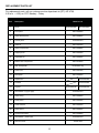
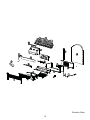
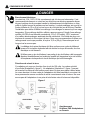
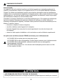
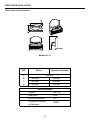
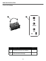
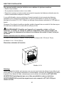
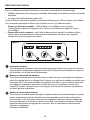
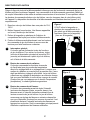
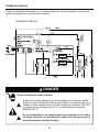
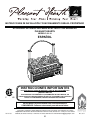
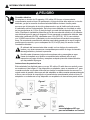
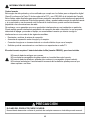
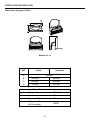
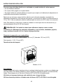
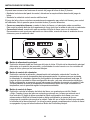
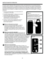
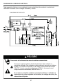
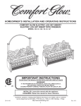
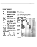
HOMEOWNER’S INSTALLATION AND OPERATING INSTRUCTIONS PLEASANT HEARTH ELECTRIC LOG SET INSERT WITH FIREBACK MODEL/MODÈLE/MODELO #LI-24 Français p. 17 Español p. 35 IMPORTANT INSTRUCTIONS PLEASE READ THIS MANUAL BEFORE INSTALLING AND USING APPLIANCE WARNING! IF THE INFORMATION IN THIS MANUAL IS NOT FOLLOWED EXACTLY, AN ELECTRICAL SHOCK OR FIRE MAY RESULT CAUSING PROPERTY DAMAGE, PERSONAL INJURY OR LOSS OF LIFE. INSTALLER: Leave this manual with the appliance. CONSUMER: Retain this manual for future reference. 20-10-105 Questions, problems, missing parts? Before returning to your retailer, call our customer service department at 877-447-4768 8:30 a.m. – 4:30 pm CST, Monday – Friday. or email us at [email protected] 1 GHP 8280 Austin Avenue M o r t o n G rove , I L . 6 0 0 5 3 - 3 2 0 7 Rev. 0/11 TABLE OF CONTENTS Safety Information ............................................................................................................................ 3 Installation Instructions ..................................................................................................................... 6 Operation Instructions ...................................................................................................................... 9 Care and Maintenance ................................................................................................................... 11 Electric Wiring Diagram .................................................................................................................. 12 Troubleshooting .............................................................................................................................. 13 Warranty ......................................................................................................................................... 14 Replacement Parts List .................................................................................................................. 15 Thank you and congratulations on your purchase of a GHP Group electric log set with heater. IMPORTANT: Read all instructions and warnings carefully before starting Installation. Failure to follow these instructions may result in a possible electric shock, injury to Please read the Installation & Operating Instructions before using this appliance. 2 SAFETY INFORMATION SAVE THESE INSTRUCTIONS Please read and understand this entire manual before attempting to assemble, operate or install the product. If you have any questions regarding the product, please call customer service at (877) 447-4768, 8:30 a.m. – 4:30 p.m., CST, Monday – Friday. 1. Read all instructions before using this appliance. 2. This appliance is hot when in use. To avoid burns, do not let bare skin touch hot surfaces. If provided, use handles when moving this appliance. Keep combustible materials, such as furniture, pillows, bedding, papers, clothes and curtains at least 3 ft. (914 mm) from the front of this appliance. 3. CAUTION: Extreme caution is necessary when any heater is used by or near children or invalids and whenever the heater is left operating unattended. 4. If possible always unplug this appliance when not in use. 5. Do not operate any heater with a damaged cord or plug or after the appliance malfunctions, has been dropped or damaged in any manner. servicing must be replaced prior to operating this appliance again. 8. Do not use outdoors. 9. This heater is not intended for use in bathrooms, laundry areas and similar indoor locations. Never place this appliance where it may fall into a bathtub or other water container. 10. Do not run cord under carpeting. Do not cover cord with throw rugs, runners or the like. 11. To disconnect this appliance, turn controls to the off position, then remove plug from outlet. 12. Connect to properly grounded outlets only. 13. This appliance, when installed must be electrically grounded in accordance with local codes, with the current CSA C22.1 Canadian Electrical codes or for USA installations, follow local codes and the National Electric Code, ANSI/NFPA No. 70. 14. Do not insert or allow foreign objects to enter any ventilation or exhaust opening as this may !" #$ % "!!&' surfaces, like a bed, where openings may become blocked. Do not place unit on carpeting or rugs. 16. This appliance has hot and arcing or sparking parts inside. Do not use it in areas where " *% a drying rack for clothing, nor should Christmas stockings or decorations be hung on or near it. 17. Use this appliance only as described in this manual. Any other use not recommended by the "!+ 18. Avoid the use of an extension cord because of the risk of overheating the cord and the risk ;& <&" =>GH"#$J#V$XY"#Z$[&#\X] and constructed of two current carrying conductors with ground. A heavy duty extension cord with the shortest length possible for the connection is recommended and must not be longer than 50 ft. (15.2 m). Do not coil or cover the extension cord. 3 SAFETY INFORMATION DANGER Electrical Connection #$^ "#Z_^["_`z Preferably, the log set will be on a dedicated circuit as other appliances on the same circuit may cause the circuit breaker to trip or the fuse to blow when the heater is in operation. The unit comes standard with a 6 ft. (1.8 m) long three wire cord, exiting the right side of the log set. Plan the installation to avoid the use of an extension cord. Extension cords are for temporary use only. If an extension cord "=>GH"#$J#"V$XY"#Z$[& #\X] ground. A heavy duty extension cord with the shortest length possible for the connection is recommended and must not be longer than 50 ft. (15.2 m). Do not coil or cover the extension cord. Electrical outlet wiring must comply with local building codes and other !"!+ to persons. Do not use this log set if any part of it has been under water. Immediately of the electrical system which has been under water. Grounding Instructions This heater is for use on 120 volts. The cord has a plug as shown at (A) in Figure 1. An adapter as shown at (C) is available for connecting three-blade grounding-type plugs to two-slot receptacles. The green grounding lug extending from the adapter must be connected to a permanent ground such as a properly grounded outlet box. The adapter should not be used if a three-slot grounded receptacle is available. Figure 1 (A) METAL SCREW COVER OF GROUNDED OUTLET BOX GROUNDING PIN (B) ADAPTER (C) GROUNDING MEANS GROUNDING PIN (D) 4 NOTE: Adapters are NOT for use in Canada. SAFETY INFORMATION Remote Control This equipment has been tested and found to comply with the limits for a Class B digital device, pursuant to Part 15 of the FCC Rules and Industry Canada ICES-003. These limits are designed to provide reasonable protection against harmful interference in a residential installation. This equipment generates, uses, and can radiate radio frequency energy and, if not installed and used in accordance with the instruction manual, might cause harmful interference to radio communications. `" < equipment does cause harmful interference to radio or television reception, which can be determined by turning the equipment off and on, the user is encouraged to try to correct the interference by one or more of the following measures: { | { < { G is connected. { G& >%[ "#$#%' DO NOT mix old and new batteries. DO NOT use rechargeable silver oxide cell batteries with remote control unit. DO NOT mix alkaline, standard (Carbon-Zinc), or rechargeable (Nickel-Cadmium) batteries. '~~% < !& CAUTION PRODUCT DAMAGE MAY OCCUR. Never attempt to disassemble or alter the product in any way not instructed by this manual. 5 INSTALLATION INSTRUCTIONS Log Set Dimensions D B C I Model #LI-24 Ref. Log Insert 23"(584mm) A B C 8-3/4"(220mm) 19-1/2"(495mm) 11-1/2"(292mm) 20"(508mm) D 13" (330mm) 21-3/4"(502mm) Technical Specifications VOLTAGE FREQUENCY MAX AMPS 120 V AC 60Hz 12A HEATER RATING 1350W 6 INSTALLATION INSTRUCTIONS Package Contents A B GHP PART DESCRIPTION QUANTITY A Electric Log Set with Heater 1 B Infrared Remote Control 1 7 INSTALLATION INSTRUCTIONS Your new electric log set with heater can be installed in several ways: { <& { ~* { < Simply place your electric log set in the desired location, observing the clearances and notes in this " #$ "#Z_[& rated for a minimum of 1,875 watts if necessary. Note: For best effect, install unit in an area out of direct sunlight and about 3-3/8” (86mm) away from a wall. Warning: Do not install unit on carpeting, rugs, beds, blankets, pillows etc. Keep combustible materials such as furniture, bedding, papers, clothes and curtains at least ;3<*'35 Clearances to Combustibles Front: 36” (915mm) Rear: 3/4” (19mm) Sides: 4-1/8” (105mm) Top: LI-24 - 3/8” (10mm) 789 Model #LI-24 Unpacking: Remove the unit from the carton and make sure that all parts are present and carefully check for damage. If any part is missing or damaged, do not attempt to assemble or use the product. Contact Customer Service for help at ())'**)+*)-( 01213455 5 0121635())'**)+*)-(3 8 OPERATING INSTRUCTION The log set control functions can be accessed in two (2) ways: { "^ { % * This allows you to operate the unit in two (2) different modes: { =3+35^*%+ ! { As a visual effect^*"X "" Figure 3 3 # 1 1 Main Power Button: This button supplies power to all the functions of the log set. The Main power button must be in the ON position, either from the remote or controls on the log set for the functions to work. # Heater Control Button: This button controls the heater ON/OFF$ =`X " % remember the last heat setting and in later use the heater will start at that setting, unless power to the unit has been interrupted. Each time the Temperature button is pressed, the temperature set point increases, allowing you to adjust the ambient temperature. 3 Flame Control button: %*`"= X"*% **ting, unless power to the unit has been interrupted. Each time the Flame button is pressed, the *%* Main Power button. 9 OPERATING INSTRUCTION The infrared remote control relies on a line of sight and must be pointed at the controls of the log set to work. The remote control unit has the controls required to turn ON/OFF both the main power and the heater. If you prefer to use the control buttons on the log set unit itself, they are on the lower right corner of the unit. The layout of the buttons and remote control unit can be seen in Figures 3 and 5, respectively. 1. Plug your log set into a 15-amp, 120-volt power outlet. 2. Turn the power on. Flame will show on the wall behind the log set. 3. Remove plastic tab from inside battery compartment to activate remote control. Figure 4 The plastic tab inside the battery compartment MUST be removed before remote control will operate. 4. Point the remote control directly at the control buttons of the log set and use the buttons to operate the log set. 1 Main Power Button: This button supplies power to all the functions of the log set. The main power button must be in the ON position, either from the remote or the controls on the log set for the functions to work. # Heater Control Button: This button controls the heater ON/OFF and 5 =`X " the lowest room temperature setting. The log set will remember the last heat setting and in later use the heater will start at that setting, unless power to the unit has been interrupted. Each time the Temperature button is pressed, the temperature set point increases, allowing you to adjust the ambient temperature. 3 Flame Control button: %* `"=X "*% * *" power to the unit has been interrupted. Each time the Flame "*% * Main Power button. 10 (Pull tab) Figure 5 1 # 3 CARE AND MAINTENANCE Before attempting ANY maintenance: 1. Turn off power to the unit. 2. Unplug the power cord from outlet. 3. Let log set cool if it has been operating. Maintenance of Motors: Always disconnect the appliance from the main power supply and allow it to cool before any servicing operation. %* ^& `" > intake and exhaust, as well as the fan heater is recommended. For heavy or continuous use, periodic cleaning must be done more frequently. If the heater blows alternating cold and warm air, check the *<" be turned off and the fan replaced immediately in order to prevent further damage to the unit. Cleaning: Cleaning of the log set is to be done only with a vacuum cleaner or by using a soft cloth, slightly dampened in water (if needed, a small amount of dish soap can be added to the water) and dried using a clean, dry soft cloth. DO NOT use any abrasive household cleaners as these products will damage the unit. 11 ELECTRIC WIRING DIAGRAM Any electrical repairs or rewiring of this unit should be carried out by a licensed electrician in accordance with national and local codes. G<|G<%'<]| DANGER Disconnect power before servicing. ^ This wiring must be done in accordance with local codes and/or in Canada with the current CSA C22.1 Canadian Electrical Code, and for US installations, the National Electrical Code ANSI/NFPA NO 70. If repairing or replacing any electrical component or wiring, the original wire routing, color coding and securing locations must be followed. 12 TROUBLESHOOTING If you have any questions regarding the product, please call customer service at (877) 447-4768 8:30 a.m. – 4:30 p.m. CST, Monday – Friday. Problem Possible Cause Corrective Action Log set does not operate; the ON/OFF power light on the control panel is not lit. 1. The log set is not plugged in. 1. Make sure the log set is plugged in #Z_[ 2. A circuit breaker is tripped or a fuse blown. 2. Check additional appliances on the circuit; ideally the log set should be on a dedicated 15-amp circuit. 3. Defective ON/OFF switch. 3. Call customer service: (877) 447-4768. 4. Loose wiring. 4. Call customer service: (877) 447-4768. Power light is ON !* is not bright/visible. 1. Incorrect operation. 1. Refer to operating instructions. 2. The unit is too far from a wall. 2. Reposition the unit closer to a wall. 3. LED strip not functioning. 3. Call customer service: (877) 447-4768. 4. Call customer service: (877) 447-4768. 4. Loose wiring. Power light is ON but the ember bed * *! 1. LED strip not functioning. 1. Call customer service: (877) 447-4768. 2. Loose wiring. 2. Call customer service: (877) 447-4768. Excessive noise * ON but the heater OFF. #|** shaft rubbing against housing. 1. Open back of electric log set and **% unit prior to servicing. Z'** shaft motor. 2. Call customer service: (877) 447-4768. ` operating. 1. Incorrect operation. 1. Refer to operating instructions. 2. Defective heater switch. 2. Call customer service: (877) 447-4768. 3. Defective heater assembly. 3. Call customer service: (877) 447-4768. 4. Loose wiring. 4. Call customer service: (877) 447-4768. 1. Dirty or clogged blower. 1. Refer to Maintenance of Motors in Care and Maintenance. Excessive noise when the heater is operating. 2. Defective heater assembly. 2. Call customer service: (877) 447-4768. 13 WARRANTY The manufacturer warrants that your new electric log set is free from manufacturing and material defects for a period of one year from date of purchase, subject to the following conditions and limitations. 1. This electric log set must be installed and operated at all times in accordance with the instructions furnished with the product. Any alteration, willful abuse, accident, or misuse of the product shall nullify this warranty. 2. This warranty is non-transferrable, and is made to the original owner, provided that the purchase z 3. This warranty is limited to the repair or replacement of part(s) found to be defective in material or workmanship, provided that such part(s) have been subjected to normal conditions of use and " 4. The manufacturer may, at its discretion, fully discharge all obligations with respect to this warranty by refunding the wholesale price of the defective part(s). 5. Any installation, labor, construction, transportation, or other related costs/expenses arising from defective part(s), repair, replacement, or otherwise of same, will not be covered by this warranty, nor shall the manufacturer assume responsibility for same. Further, the manufacturer will not be responsible for any incidental, indirect, or consequential damages, except as provided by law. 6. All other warranties - expressed or implied - with respect to the product, its components and accessories, or any obligations/liabilities on the part of the manufacturer are hereby expressly excluded. 7. %"z "" any other liabilities with respect to the sale of this product. 8. The warranties as outlined within this document do not apply to non-manufacturer accessories used in conjunction with the installation of this product. This warranty is void if: Y % "* damaging chemicals. b) The log set is subjected to prolonged periods of dampness or condensation. c) Any alteration, willful abuse, accident, or misuse of the product. IF WARRANTY SERVICE IS NEEDED . . . 1) Contact customer service. Make sure you have your warranty, your sales receipt, and the model/serial number of your product. ZY'~~%%%;%%~'~H;|[<G;X~|~|H;= GHP Group, Inc. GHP 8280 Austin Avenue ]"<= 60053-3207 14 REPLACEMENT PARTS LIST For replacement parts, call our customer service department at (877) 447-4768, 8:30 a.m. – 4:30 p.m. CST, Monday – Friday. Ref. Model #LI-24 Description 1 Fence EFLH24359AC 2 Front panel EFLH24358AC 3 Plastic button panel EFLH24360AC 4 Control panel EF23023102X 5 Channel EFLH24357AC 6 Heater components EFLH24369AC 7 Support panel EFLH24353AC 8 Adjustable leg EFLH24364AC 9 Bottom case components EFLH24100AC 10 Main board(PCB) EF33503AC-log 11 Power cord EFLH24372AC 12 Back panel EFLH24350AC 13 Square tube EFLI24350AC 14 Fireback EFLI24100AC 15 Log Set 16 LED ARRAY II (log set light) EF23023104X 17 Plastic lining EFLH24362AC 18 Flame panel EFLH24354AC 19 Flame reflector EFLH24367AC 20 Plastic panel EFLH24363AC 21 Synchronous motor EFLH24368AC 22 LED ARRAY I (flame light) EF23023103X 23 Remote control EFLH24361AC EFLH24359AC EFLI24361AC EF33510AS 15 Printed in China 16 DIRECTIVES D’INSTALLATION ET D’UTILISATION JEU DE BÛCHES ÉLECTRIQUE ENCASTRABLE AVEC PANNEAU ARRIÈRE PLEASANT HEARTH MODÈLE Nº #LI-24 FRANCÁIS CONSIGNES IMPORTANTES VEUILLEZ LIRE CE MANUEL AVANT D’INSTALLER OU D’UTILISER LE FOYER. AVERTISSEMENT! RESPECTEZ SCRUPULEUSEMENT LES DIRECTIVES DU PRÉSENT MANUEL POUR PRÉVENIR LES CHOCS ÉLECTRIQUES, LES INCENDIES, LES DOMMAGES AINSI QUE LES BLESSURES GRAVES OU MORTELLES. "87="@Q8Z[\282\1208[\29==8Q"]^_ "87="@Q8Z[\282\120Q\82]^ _3__ 20-10-105 Des questions, des problèmes, des pièces manquantes? Avant de retourner " zV\\\V" V_#_"`G""z^ 17 GHP 280 Austin Avenue M o r t o n G rove , I L . 0 0 5 3 - 3 2 0 7 Rev. 0/11 TABLE DE MATIÉRES G .................................................................................................................... 20 ' ................................................................................................................... 24 ' ..................................................................................................................... 28 Entretien ......................................................................................................................................... 30 H ........................................................................................................................ 31 ' ..................................................................................................................................... 32 ] .......................................................................................................................................... 34 Liste des pièces de rechange ......................................................................................................... 35 23_}_6 6~_GHP Group. \7z1"=2] _{[+ _65 ^[[[| bûches. 18 CONSIGNES DE SÉCURITÉ CONSERVEZ CES DIRECTIVES [z " Hz "z JVY\\^\V"V_#_"`G" # =z+ Z G+"z &H+ "z^ z^"" oreillers, la literie, le papier, les vêtements et les rideaux, se trouvent au moins 914 mm (3 pi) de 3. MISE EN GARDE : Faites preuve d’une extrême prudence lorsqu’un radiateur _{_3_ 3 \ ' "z+ $ z "+ "+ Gz z+|z V z & = " z+ #_ z z " z ## "z " z #Z z # ="z& &" G"GHGZZ#" &^"&&"H<> Nº 70. #\ z++"" #$ "z+ 19 CONSIGNES DE SÉCURITÉ z " " z tapis. # G z " * G rations. # z % "trique ou des blessures. #V z = H" z^=>GH#$ J#V$Y"#Z$[&"#\ & " #$"ZJ$_ Yz z CONSERVEZ CES DIRECTIVES 20 CONSIGNES DE SÉCURITÉ DANGER _ #$"#Z_["_`z< + + = #"VJ Y+z = H"z^ =>GH#$J#V$Y"#Z$[&" #\& " #$"ZJ$_ Yz z = & &" z + + z + 0{ G#Z_= J"#Y JG"#Y & & = z Figure 1 VIS MÉTALLIQUE COUVERCLE DE LA BOÎTE DE SORTIE MISE À LA TERRE BROCHE DE MISE À LA TERRE (A) (B) ADAPTATEUR (C) COSSE DE MISE À LA TERRE BROCHE DE MISE À LA TERRE (D) 21 Avertissement: 2[z=9[ au Canada. CONSIGNES DE SÉCURITÉ __ G & & "#$GG^__< GG G " " &" & G " &H J Y" ¡" { ¢ { ¢ { ¢ { & Q63"#$#%'__ %<=<H;£H %<=<H;£H &^ %<=<H;£H "J^zY (nickel-cadmium) ensemble. ;¤;%;£H ou faire exploser les piles. ATTENTION LES DOMMAGES DE PRODUIT PEUVENT SE PRODUIRE. z+ 22 DIRECTIVES D’INSTALLATION Dimensions du jeu de bûches D B C I Modèle #LI-24 Réf. Bûche Appareil encastrable 584 mm A B C 220 mm 495 mm 292 mm 508 mm D 330 mm 502 mm Fiche technique Tension Fréquence Intensité Maximale Puissance Nominale du Radiateur 23 120 V AC 60Hz 12A 1350W DIRECTIVES D’INSTALLATION }65 A B GHP PIÈCE DESCRIPTION QUANTITÉ A Ensemble de bûches avec radiateur 1 B Télécommande à infrarouge 1 24 DIRECTIVES D’INSTALLATION ^|6~] { '&¢ { H "¢ { ' ^ <+" #$"#Z_[z #V$ besoin. |"z VJ>V Y Avertissement:2[[ 666 {}<*;'| de bûches. Distance minimale avec les matières combustibles ¡#$J Y¡#J>\ Y'#_$J\#>V Y Au-dessus: LI-24 - 10 mm (3/8 po) 0} Modèle #LI-24 0_65] |z " z^z ^ H "z "z())'**)+*)-( NE JETEZ PAS l’emballage tant que vous n’êtes pas satisfait de votre jeu de bûches. 28"81Q"28z=95_())'**)+*)-( obtenir de l’aide. 25 DIRECTIVES D’UTILISATION '&JZY & { " { =+ * G +&JZY { Comme jeu de bûches complet¥* G {Comme effet visuel seulement¥*" " Figure 3 3 # 1 1 \5__] G +" z ~JY +" # Bouton de commande du radiateur: G =z " =+ z" G z% J Y" 3 ] G *J"" Y=*& +. Le +* z" < * H * 26 DIRECTIVES D’UTILISATION 'z+ = H z +"z = $ respectivement. Figure 4 # z+ dans une prise de 15 A, Il FAUT retirer la languette en #Z_[ plastique du compartiment de la Z z * "+ JzY |z (z) \ z +z^ boutons pour faire fonctionner ce dernier. 1 \5__] G +"z ~ JY +" # Bouton de commande du radiateur: Ce bouton commande les fonctions de marche = z " =+ z" G z% J Y" 3 ] G *J""Y= *& +=+ * z" Il est * appuyant sur ce bouton. Seul le commutateur principal permet * 27 Figure 5 1 # 3 ENTRETIEN Avant TOUT entretien : # G z Z 'z =z+ Entretien des moteurs : 0_6|_5[_+ _53 =** &< " z H " zH "z" z Nettoyage : z+ & J"+z Y" z^&" propre et sec. N’UTILISEZ PAS de nettoyants abrasifs, car ces produits endommageront l'appareil. 28 SCHÉMA DE CÂBLAGE Gz && HG`';G§=]; DANGER [[ Gz [z&&" G" G"GHGZZ# "&^"" ANSI/NFPA Nº 70. 8_[[6 _[6 [5 29 DÉPANNAGE Hz "z JVY\\^\V"V_#_"`G" Problème Cause possible Mesure corrective =+ #=+ fonctionne pas, le voyant 2. tableau de < & \G #z^+ #Z_[ Z[z <" #$ Gz clientèle au (877) 447-4768. \Gz clientèle au (877) 447-4768. Le voyant 1. Fonctionnement incorrect. Z= " loin du mur. * pas lumineuse 3. La bande de DÉL ne ni visible. fonctionne pas. #Gz Z| z Gz clientèle au (877) 447-4768. \G \Gz clientèle au (877) 447-4768. Le voyant " de braise ne scintille pas. 1. La barrette de DÉL ne fonctionne pas. #Gz clientèle au (877) 447-4768. ZG ZGz clientèle au (877) 447-4768. Le bruit est excessif * que le radiateur #=* * contre le boîtier. #~z z** z Z= ** & 30 ZGz clientèle au (877) 447-4768. DÉPANNAGE Hz "z JVY\\^\V"V_#_"`G" Problème Cause possible Mesure corrective Le radiateur ne fonctionne pas. 1. Fonctionnement incorrect. #Gz 2. Interrupteur de radiateur & ZGz clientèle au (877) 447-4768. 3. Ensemble de radiateur & Gz clientèle au (877) 447-4768. \G \Gz clientèle au (877) 447-4768. #H* #Gz des moteurs. Le bruit est excessif lorsque le radiateur est en fonction. 2. Ensemble de radiateur & ZGz clientèle au (877) 447-4768. 31 GARANTIE =& & " conditions et des restrictions suivantes. 1. Ce + & " " 2. G " z 3. G &" + &" 4. = "" & 5. %"^¨"" "& " " " ' " "& 6. Toutes les autres garanties, explicites ou implicites, sur le produit, ses composants et ses & & 7. = "" 8. = 5_] Y =+ "* Y =+& Y = +"" ou a subi un accident. SERVICE AU TITRE DE LA GARANTIE . . . #Y Gzz^ " produit de le fabricant. ZY ;%;%;£H';||;|=;|~'<%[~H^©; GHP Group, Inc. 32 GHP 8280 Austin Avenue ]"<= 60053-3207 LISTE DES PIÈCES DE RECHANGE "z JVY\\^\V"V_#_"`G" Réf. Modèle #LI-24 Description 1 Guide longitudinal EFLH24359AC 2 Panneau avant EFLH24358AC 3 Panneau des boutons en plastique EFLH24360AC 4 Panneau de commande EF23023102X 5 Rainure EFLH24357AC 6 Élément du radiateur EFLH24369AC 7 Panneau de soutien EFLH24353AC 8 Pied réglable EFLH24364AC 9 Éléments de la partie inférieure EFLH24100AC 10 Panneau principal (carte de circuit imprimé) EF33503AC-log 11 Cordon d’alimentation EFLH24372AC 12 Panneau arrière EFLH24350AC 13 Tube carré EFLI24350AC 14 Panneau arrière de foyer EFLI24100AC 15 Ensemble de bûches 16 RANGÉE DE DEL II (lumière de l’ensemble de bûches) EF23023104X 17 Revêtement en plastique EFLH24362AC 18 Panneau de flamme EFLH24354AC 19 Réflecteur de flamme EFLH24367AC 20 Panneau de plastique EFLH24363AC 21 Moteur synchrone EFLH24368AC 22 RANGÉE DE DEL I (lumière de la flamme) EF23023103X 23 Télécommande EFLH24361AC EFLH24359AC EFLI24361AC EF33510AS 33 < G 34 INSTRUCCIONES DE INSTALACIÓN Y FUNCIONAMIENTO PARA EL PROPIETARIO ACCESORIO DE JUEGO DE LEÑOS ELÉCTRICO CON RESPALDO PLEASANT HEARTH MODELO #LI-24 ESPAÑOL INSTRUCCIONES IMPORTANTES LEA ESTE MANUAL ANTES DE INSTALAR Y USAR EL ELECTRODOMÉSTICO ¡ADVERTENCIA! SI NO SE SIGUE CON PRECISIÓN LA INFORMACIÓN DE ESTE MANUAL, SE PUEDE PRODUCIR UNA DESCARGA ELÉCTRICA O UN INCENDIO QUE PRODUZCA DAÑOS A LA PROPIEDAD, LESIONES PERSONALES O MUERTE. \29==01"]0|_ CONSUMIDOR: Conserve este manual para referencia futura. 20-10-105 «" " z¬" departamento de Servicio al Cliente llamando al 877-447-4768, de 8:30 a.m. a 4:30 p.m. hora central ®""¯ 35 GHP 8280 Austin Avenue M o r t o n G rove , I L . 6 0 0 5 3 - 3 2 0 7 Rev. 0/11 ÍNDICE <¯ ............................................................................................................... 39 <¯ ........................................................................................................... 43 < ¯............................................................................................................. 47 Cuidado y mantenimiento ............................................................................................................... 49 ' .................................................................................................... 50 H¯ ................................................................................................................... 51 ].......................................................................................................................................... 53 = z ............................................................................................................ 54 Gracias y felicitaciones por la compra de su juego de _z"1Qz IMPORTANTE: lea con atención todas las instrucciones y advertencias antes de 95 5_55 Lea estas instrucciones de instalación y funcionamiento _ 36 INFORMACIÓN DE SEGURIDAD GUARDE ESTAS INSTRUCCIONES Lea y comprenda completamente este manual antes de intentar ensamblar, usar o instalar el producto. Si tiene preguntas relacionadas con el producto, llame al Servicio al Cliente al (877) 447-4768, de 8:30 a.m. a 4:30 p.m. hora central estándar, de lunes a viernes. # = Z ;®" H"+ *""" ropa de cama, papeles, ropa y cortinas al menos a 914,4 mm (3 pies) de la parte delantera 3. PRECAUCIÓN: Se debe tener extrema precaución cuando niños o personas discapacitadas usen un calentador o cuando se use cerca de ellos, y siempre que el calentador se deje funcionando sin vigilancia. \ H " $ °±" " de que se haya dejado caer o dañado de cualquier forma. % ¯z += z ¯ z 8. No lo use en exteriores. 9. Este calentador no se debe usar en el baño, lavadero y en espacios húmedos similares interiores. Nunca coloque este calentador donde se pueda caer dentro de una bañera u otro contenedor de agua. 10. No coloque el cable debajo de una alfombra. No cubra el cable con alfombras, tapetes o G+z® z ## " ¯ retire el enchufe del tomacorriente. 12. Conecte únicamente a un tomacorriente con la debida puesta a tierra. # G®" °¯" °G¯;G®GHGZZ#" ;;" ¯¯"H<>_ #\ z+&± ¯" "± 15. Para evitar incendios, no bloquee las entradas ni salidas de aire de ninguna manera. No use so "" la unidad sobre alfombras o tapetes. # ; z z ®" *;+ " ± 37 INFORMACIÓN DE SEGURIDAD # ¯G " lesiones personales. #V ;z&" =&¯ ' &¯"=>GH"#$J#V$XY" #Z$[®&#\X] H&¯ + &¯" #$"Z\J$_ Y &¯ GUARDE ESTAS INSTRUCCIONES 38 INFORMACIÓN DE SEGURIDAD PELIGRO _ H#$ "#Z_"_`z correctamente puesto a tierra. De preferencia, el juego de leños debe estar en un circuito "&¯ provocar que el interruptor de circuito se desconecte o que el fusible se funda cuando H® de tres conductores de 1,83 m (6 pies) de largo, que sale del lado derecho del juego de ±¯ &¯=&¯ '&¯" =>GH"#$J#V$XY"#Z$[®& #\X] H&¯ + &¯" #$"Z\J$_ Y &¯ ; ¯¯ locales y con otras normas que correspondan para reducir el riesgo de incendio, z = +± z que haya estado bajo agua. Instrucciones de puesta a tierra Este calentador fue diseñado para su uso en 120 voltios. El cable tiene un enchufe, como #` "G" conectar enchufes con puesta a tierra de tres clavijas a receptáculos de dos ranuras. La orejeta verde de puesta a tierra que sale del adaptador se debe conectar permanentemente "+ ; adaptador no se debe usar si hay disponible un receptáculo de tres ranuras puesto a tierra. Figura 1 TORNILLO DE METAL TAPA DE LA CAJA DEL TOMACORRIENTE PUESTO A TIERRA CLAVIJA CON PUESTA A TIERRA (A) ADAPTADOR (C) PUESTA A TIERRA CLAVIJA CON PUESTA A TIERRA (D) 39 NOTA: Los adaptadores NO son INFORMACIÓN DE SEGURIDAD Control remoto ; Clase B, conforme a la Parte 15 de las reglas de la FCC y con ICES-003 de la Industria de Canadá. ;®± ¯z + ¯; "z y, si no se instala y usa de acuerdo con el manual de instrucciones, puede causar interferencia perjudicial a las comunicaciones de radio. H"z ®¯ H + ¯¯" determinar al apagar y encender el equipo, se recomienda al usuario que intente corregir la interferencia con una o más de las siguientes medidas: { | ¯ { ¯ { Conectar el equipo a un tomacorriente de un circuito distinto al que usa el receptor. { H& >%[ 866"#$#%' ~z ~ ^ ~z"®Jz^YJY ~¯ & PRECAUCIÓN EL DAÑO DEL PRODUCTO PUEDE OCURRIR. Nunca intente desmontar o alterar el producto de cualquier manera no instruida por este manual. 40 INSTRUCCIONES DE INSTALACIÓN Dimensiones del juego de leños D B C I Modelo #LI-24 Ref. A B C D Leños Accesorio 584 mm 220 mm 495 mm 330 mm 292 mm 508 mm 502 mm Especificaciones técnicas Voltaje Frecuencia Amperaje Máximo 120 V AC 60Hz 12A Potencia de Servicio del Calentador 1350W 41 INSTRUCCIONES DE INSTALACIÓN Contenido del paquete A B GHP PIEZA DESCRIPCIÓN CANTIDAD A Juego de leños eléctrico con calentador 1 B Control remoto infrarrojo 1 42 INSTRUCCIONES DE INSTALACIÓN 9|5_] { ;& { ; ¯ ¯ { H + ¯ +±¯" ¯" #$#Z_[&¯ #V$ +"®+z aproximadamente 86 mm (3 3/8”) de la pared. Advertencia: No instale la unidad sobre alfombras, tapetes, camas, mantas, 75 66 $<;'|5 Distancia de separación con combustibles Parte frontal: 0,91 m (36”) Parte posterior: 1,91 cm (¾”) Laterales: 10,5 cm (4 1/8”) Parte superior: LI-24 - 10 mm (3/8”) Modelo #LI-24 Desembalaje: |+° z ± z®±GHGJVY\\^\V 21_3|5 21())'**)+*)-( 43 INSTRUCCIONES DE OPERACIÓN Si puede tener acceso a las funciones de control del juego de leños de dos (2) formas: { Mediante los botones del panel de control, ubicado en la esquina inferior derecha del juego de leños. { El juego de leños ofrece controles convenientemente separados para efecto de llamas y para control del calentador. Esto le permite operar la unidad de dos (2) modos diferentes: { Como una completa chimenea, cuando el efecto de llamas y el calentador están encendidos. Este modo le permite disfrutar de la apariencia de fuego junto con la salida de calor de un calentador. { Como efecto visual"¯®" | ¯®" chimenea, pero sin salida de calor. 3 # 1 1 Botón de alimentación principal: ;¯++±;¯¯ ¯" juego de leños, para que las funciones trabajen. # Botón de control del calentador: ;¯¯¯"®$ + = z "®¯ ®+; +±®°¯® ¯" G z ¯ "® temperatura, esto le permitirá regular la temperatura ambiente. 3 Botón de control de llama: ;¯z"" +G+± z" nivel más alto. ;+±®°¯* *®¯" Gz¯ " z=° +±¯; 44 INSTRUCCIONES DE OPERACIÓN ;+z¯ + de leños para que funcione. La unidad de control remoto cuenta con los controles necesarios para ¯ H de control de la unidad misma, estos se encuentran en la esquina inferior derecha de la unidad. La ¯ $ tivamente. 1. Enchufe el juejo de leños en un tomacorriente de 15 amperios y 120 voltios. Z;¯=® en la pared detrás del juego de leños. 3. Retire la lengüeta plástica del interior del J$Y 4. Apunte el control remoto directamente a los botones de control del juego de leños y use los botones para operarlo. Figura 4 La lengüeta plástica dentro del ';; retirar para que el control remoto pueda funcionar (tire de la lengüeta). (tire de la lengüeta) 1 Botón de alimentación principal: ;¯¯ +±;¯ ¯ ¯ encendido, ya sea desde el control remoto o en los controles del juego de leños, para que las funciones trabajen. # Botón de control del calentador: ;¯¯¯ calentador, además de 5 modos de temperatura que + = z "®¯ temperatura ambiente más baja. El juego de leños recordará la °¯® ¯" Gz ¯ "^® se establece la temperatura, esto le permitirá regular la temperatura ambiente. 3 Figura 5 Botón de control de llama: ;¯z" graduaciones de Alto, Medio y Bajo. Cuando el juego de leños z" más alto. %* * setting, unless power to the unit has been interrupted. Cada z¯ "z llama disminuye. La única forma de apagar completamente el +±¯ Encendido principal. 45 1 # 3 CUIDADO Y MANTENIMIENTO =Q=@Q\8"] 1. Apague la unidad. Z '¯ '++± Mantenimiento de los motores 9__ 3 Los motores usados en el calentador de ventilador y el soplador de llamas vienen lubricados °¯H " z ¯ ¯ " " z ¯zH ®" *+H" z ± = z = z+±z¯ ±" J" ±+¯ Y ±~ abrasivos, ya que pueden dañar la unidad. 46 DIAGRAMA DEL CABLEADO ELÉCTRICO % ¯¯z ¯ '<]|';G<|G<%~ PELIGRO 0 %z ;z¯ "G®"G¯;G® CSA C22.1 actual, y para las instalaciones en EE.UU., de acuerdo con el ¯"H<>_ 9_6 deben seguir las rutas originales de los cables, los códigos de color y las 6 | 47 SOLUCIÓN DE PROBLEMAS Si tiene preguntas relacionadas con el producto, llame al Servicio al Cliente al (877) 447-4768, de 8:30 a.m. a 4:30 p.m. hora central estándar, de lunes a viernes. Problema Causa posible Acción correctiva El juego de leños no 1. El juego de leños no está ¢z enchufada. encendido del panel 2. Un interruptor de circuito se de control no está ¯¯ encendida. fusible. 3. Interruptor de ENCENDIDO/ ]'~ 4. Cableado suelto. 1. Asegúrese de que el juego de leños ®#Z_[ 2. Compruebe si hay otros circuito; idealmente, el juego de leños debe estar conectada a un circuito dedicado de 15 amperios. 3. Llame a Servicio al Cliente al (877) 447-4768. 4. Llame a Servicio al Cliente al (877) 447-4768. =z 1. Funcionamiento incorrecto. está encendida pero 2. La unidad está muy lejos de la llama posterior la pared. no brilla o no está visible. 3. La tira del LED no funciona. 4. Cableado suelto. #G ¯ ZG ¯® cerca a una pared. 3. Llame a Servicio al Cliente al (877) 447-4768. 4. Llame a Servicio al Cliente al (877) 447-4768. =z 1. La tira del LED no funciona. está encendida pero 2. Cableado suelto. la llama del lecho de brasas no titila. 1. Llame a Servicio al Cliente al (877) 447-4768. Ruido excesivo cuando la llama está encendida pero el calentador está apagado. 1. Abra la parte posterior del juego de ±+ ¯ +* z #;+* giratorio se está friccionando contra la carcasa. Z+* llamas defectuoso. 48 2. Llame a Servicio al Cliente al (877) 447-4768. 2. Llame a Servicio al Cliente al (877) 447-4768. SOLUCIÓN DE PROBLEMAS Si tiene preguntas relacionadas con el producto, llame al Servicio al Cliente al (877) 447-4768, de 8:30 a.m. a 4:30 p.m. hora central estándar, de lunes a viernes. Problema Causa posible Acción correctiva El calentador no funciona. 1. Funcionamiento incorrecto. #G ¯ 2. Interruptor del calentador defectuoso. 2. Llame a Servicio al Cliente al (877) 447-4768. 3. Ensamble del calentador defectuoso. 3. Llame a Servicio al Cliente al (877) 447-4768. 4. Cableado suelto. 4. Llame a Servicio al Cliente al (877) 447-4768. 1. Soplador sucio u obstruido. #G¯ de los motores del manual de instrucciones. Ruido excesivo cuando el calentador está funcionando. 2. Ensamble del calentador defectuoso. 2. Llame a Servicio al Cliente al (877) 447-4768. 49 GARANTÍA ;z ®¯ ± " cumplan las siguientes condiciones y limitaciones. # ; ¯ ¯ G¯" " ® Z ;¯® " z zG ± ; ¯ z z " z " ¯ G ± dicho defecto. \ =G ± ®"+"&¯ z $ ;®°¯""¯" + z" ¯" z¯" G ±® =G ± ® responsable por ningún daño accidental, indirecto o resultante, salvo que la ley estipule lo contrario. "&& "& " " "¯ G ± =G ±"z°" responsabilidad respecto de la venta de este producto. V = +¯ 85] Y ;+±¯"*° ± Y ;+±® ¯ Y H ¯"" SI SE NECESITA SERVICIO DE GARANTÍA. . . #Y ¯HG °" modelo o número de serie de su producto el fabricante. ZY ~<%;%;|;=<£|<]³%|¤~ GHP Group, Inc. DE REPARACIÓN USTED MISMO. GHP 50 8280 Austin Avenue ]"<= 60053-3207 LISTA DE PIEZAS DE REPUESTO z " HG (877) 447-4768, de 8:30 a.m. a 4:30 p.m. hora central estándar, de lunes a viernes. Ref. Modelo #LI-24 Descripción 1 Guía EFLH24359AC 2 Panel delantero EFLH24358AC 3 Panel de botones de plástico EFLH24360AC 4 Panel de control EF23023102X 5 Canal EFLH24357AC 6 Componentes del calentador EFLH24369AC 7 Panel de apoyo EFLH24353AC 8 Pata ajustable EFLH24364AC 9 Componentes de la caja inferior EFLH24100AC 10 Tablero principal (PCB) EF33503AC-log 11 Cable de alimentación EFLH24372AC 12 Panel posterior EFLH24350AC 13 Tubo cuadrado EFLI24350AC 14 Respaldo EFLI24100AC 15 Juego de leños 16 DISPOSICIÓN DE LUCES LED II (luz del juego de leños) EF23023104X 17 Forro de plástico EFLH24362AC 18 Panel de llamas EFLH24354AC 19 Reflector de llamas EFLH24367AC 20 Panel plástico EFLH24363AC 21 Motor síncrono EFLH24368AC 22 DISPOSICIÓN DE LUCES LED I (luz de llamas) EF23023103X 23 Control remoto EFLH24361AC EFLH24359AC EFLI24361AC EF33510AS 51 Impreso en China 52