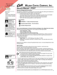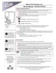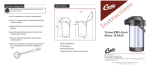
1
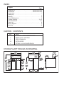
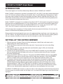
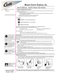
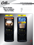
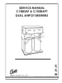
SERVICE MANUAL C1000AP & C1000APT DUAL AIRPOT BREWERS Wilbur Curtis Co., Inc. Montebello, California 90640 Telephone 323/837-2300 Fax 323/837-2406 INDEX Subject Page Shipping List . . . . . . . . . . . . . . . . . . . . . . . . . . . Inside Front Cover Dimensions . . . . . . . . . . . . . . . . . . . . . . . . . . . . Inside Front Cover Introduction . . . . . . . . . . . . . . . . . . . . . . . . . . . . . . . . . . . . . . . . . 1 Setting Up . . . . . . . . . . . . . . . . . . . . . . . . . . . . . . . . . . . . . . . . . . 1 Brewing . . . . . . . . . . . . . . . . . . . . . . . . . . . . . . . . . . . . . . . . . . . . 2 Care & Maintenance . . . . . . . . . . . . . . . . . . . . . . . . . . . . . . . . . . 3 Trouble Shooting . . . . . . . . . . . . . . . . . . . . . . . . . . . . . . . . . 3, 4, 5 Parts Breakdown . . . . . . . . . . . . . . . . . . . . . . . . . . . . . . . . . . . 6, 7 Parts List . . . . . . . . . . . . . . . . . . . . . . . . . . . . . . . . . . . . . . . . . 8 Wiring Diagram . . . . . . . . . . . . . . . . . . . . . . . . . . . . . . . . . . . . . 9 Warranty . . . . . . . . . . . . . . . . . . . . . . . . . . . . . . . . . . . . . . . . . . 10 CARTON CONTENTS QTY ITEM 1 C1000 AP or APT COFFEE BREWER 2 BREW CONE, UNIVERSAL 1 SERVICE MANUAL 25 FILTER PAPER 1 FITTING, 1/4 x 3/8 FLARE ELBOW C1000AP & APT ROUGH-IN DRAWING C1000AP C1000APT C1000AP C1000APT C1000AP C1000AP C1000APT C1000APT C1000AP & C1000APT Airpot Brewer INTRODUCTION This manual applies to Curtis Dual Station Airpot Brewer models C1000AP and C1000APT. Model C1000AP is designed for use with Curtis Airpots CAP-1 thru CAP-5, and other insulated dispensers up to 13¾" tall when opened for filling (see illustration, Step 3 in Coffee Brewing). Starting early in 1994, this brewer was increased in height to accommodate the larger "Deluxe" stainless steel brew cone. The taller brewer will also allow you to use insulated dispensers to 14¾" tall with the Universal (plastic) brew cone or the optional stainless steel brew cone. Model C1000APT is designed for use with the Curtis Airpot CAP-T1 with integral serving stand and gauge glass and other insulated dispensers to 18" tall in filling position. It can also be used with the larger Gourmet brew cone, but will then accept only insulated dispensers of 17" or less. You can use CAP-T1 and CAP-1 thru CAP-5 airpots in combination with all brew cones on the C1000APT. All Curtis airpots have a capacity of 2.2 liters and the brewers are preset at the factory. You can vary the amount of coffee brewed by adjusting the brew timer. Brewers with the Universal (plastic) brew cone or the optional stainless steel brew cone of the same size use CR-10 filters. The larger Deluxe brew cone uses GEM-6 filters. See Airpot Accessory Sheet (packed with your manual) to identify your brew cone and for information on other Curtis accessories. SETTING UP THE COFFEE BREWER 1. Remove top cover of brewer. Remove lid from heating tank. Hand fill tank until water level is approximately two inches below probe tip. 2. A 1/4" flare fitting is required to hook-up the water inlet. Connect water line to inlet valve fitting. Turn on water. 3. With top cover removed, locate the thermostat (see illustration, page 5, #30), turn thermostat knob (#32) clockwise until it stops. 4. Connect unit into appropriate power circuit. Flip POWER SWITCH (behind unit) ON. Water should flow into heating tank (and the heaters will come on). Check that water shuts off when it reaches the probe inside the tank. 5. Turn on the ON/OFF SWITCH on the front. This powers the BREW TIMERS. Place an empty BREW CONE into the guide rails for the left brewer, and an empty airpot beneath it. Press the left BREW SWITCH to start the brew cycle. Repeat the test on the right brewer when the water is hot. 6. If necessary, the brew volume for either station can be increased or decreased by adjusting the appropriate timer. Left and right brewers can be set for different volumes if you use two sizes of insulated dispensers (the quantity of ground coffee needed in the brew will change when a timer has been adjusted). TURN OFF POWER SWITCH ON BACK. Rotate the appropriate timer knob slightly to increase or decrease time and brew volume. Run a brew cycle to verify the brew volume. When you are satisfied with the adjustment, install the top cover and tighten the cover screws. The READY TO BREW light will come on when the water in the heating tank reaches brewing temperature. For best results, do not brew coffee until this light is on. It is normal for the light to go out as soon as brewing begins. IMPORTANT: The timer is adjusted at the factory to brew into a standard 2.2 liter airpot and has been set between 3 min. 20 sec. to 3 min. 40 sec.. The timer shall not be set longer than 4 min.. [1] C1000AP & C1000APT Airpot Brewer COFFEE BREWING 1. With a clean filter in place, pour ground coffee into the brew cone. You may need to experiment to determine the correct quantity of ground coffee for your tastes, but a consistent measure of ground coffee is necessary for controlling the quality of flavor in your brewed coffee. 2. Slide brew cone onto the guide rails as far in as it will go. Place an empty airpot beneath the cone. Note that most airpots must be opened and the siphon assembly removed for filling. Preheating the airpot can increase the serving temperature by 4º-5º F. 3. Make sure that both the ON/OFF switch and READY TO BREW light is ON. Pushing the brew switch will start the brew cycle. If necessary, the brew cycle may be canceled at any time by pressing the ON/OFF switch to OFF. CAUTION: TO AVOID SCALDING HAZARD FROM HOT LIQUID, do not remove the airpot or brew cone until the brew cycle is complete and the grounds [2] C1000AP & C1000APT Airpot Brewer CARE AND MAINTENANCE OF C1000 AP Preventive maintenance is essential in keeping your Curtis coffee brewer performing at it's peak. Regular cleaning will pay off with an appealing, high performance, coffee brewing machine. Preventive Maintenance 1. Remove the sprayhead from brewer and clean it once a week; more often in heavy lime areas. 2. The inside of the heating tank may, occasionally, require removing of lime build-up. The frequency is determined by local water conditions. Cleaning Using a daily routine of cleaning, the external parts of the C1000 AP should maintain it's new appearance and ensure that the flavor of the coffee is always good. 1. Wipe off any spills, dust or debris that may fall on exterior surfaces. 2. Slide out the brew cone and rinse. 3. Clean sprayhead and dome around the sprayhead. Use a non-toxic cleaner. 4. Clean the brew cone slide rails with a brush or damp cloth. Dry thoroughly. Stainless Steel Polish can be used to clean the outside surfaces of the C1000 AP coffee brewer. This is to prevent scratching of the stainless steel surfaces. CAUTION - Do not use cleansers, bleach liquids, powders or any other substance containing chlorine. These products will promote corrosion and will pit the stainless steel. USE OF THESE PRODUCTS WILL VOID YOUR WARRANTY. TROUBLESHOOTING These procedures apply specifically to model C1000AP-10 and C1000APT-10. They also apply to airpot brewers with other dash numbers which are based on the -10 schematic, primary units rated 220 volts, 5100 watts, three wire plus ground. If the serial nameplate electrical rating differs, some measured voltages, currents, and resistances will be different than shown on the standard -10 schematic. PROBLEM: WATER DOES NOT FLOW INTO HEATING TANK. POSSIBLE CAUSE 1. Water line turned off or water filter needs changing 2. Water inlet valve coil burned out SOLUTION Open the line and make sure you are getting enough water to brewer. Turn machine off. Disconnect wires from water inlet coil terminals and connect a power cord to the terminals. Plug cord into a 120V outlet and verify if water flows when plugged in and stops when power is disconnected. If valve fails this test, replace valve. [3] C1000AP & C1000APT Airpot Brewer TROUBLE SHOOTING CONTINUED: PROBLEM: WATER DOES NOT FLOW INTO HEATING TANK. POSSIBLE CAUSE SOLUTION 3. Grounded probe When the water level gets below the probe tip, water should automatically refill the tank. If not, pull wire off the probe terminal. Water should now start flowing into the tank. If not, check the water level control board (see step 4) or inlet valve (step 2). 4. Defective water level control board Disconnect wire from probe terminal. With a voltmeter, check voltage at the water inlet coil terminals. This should read 110-120 volts. If no voltage is present, check liquid level control (L.L.C.) board. Make sure the L.L.C. board is supplied by 120V across terminals T2 & T3. The L.L.C. board is grounded to the chassis of the machine by contacting the board to the mounting bracket. Make sure board is grounded here. Check for loose connections at terminals. Replace board. PROBLEM: WATER HEATING TANK OVERFLOWING. SOLUTION POSSIBLE CAUSE 1. Defective water inlet valve Turn power off and observe water level. If water continues to flow into the heating tank, clean or replace leaky valve. 2. Probe limed-up Disconnect wire from probe terminal. Touch the body of the heating tank with the terminal at the end of this wire. If water stops, try cleaning the probe. Probe may have to be replaced. 3. Non-grounded or loose terminal connections at liquid level control board Liquid level control board must be securely grounded through the back of the board and the mounting bracket. Check for loose connections at the terminals. Check for voltage across the inlet valve terminals. If there is 110 to 120 volts present at the inlet valve terminals when water level is touching the probe tip, replace the L.L.C. board. PROBLEM: WATER IN TANK DOES NOT REACH PROPER TEMPERATURE POSSIBLE CAUSE 1. Thermostat turned OFF (or not fully ON). 2. Defective thermostat 3. Defective Contactor SOLUTION Check thermostat to make sure the shaft is rotated fully clockwise until it stops. Replace thermostat if contacts are open when shaft is fully clockwise and water temperature is less than 190º F. You will measure 120 volts (approximately) to ground from both thermostat terminals when it is ON and from only one terminal when it is OFF. Measure the voltage across the coil terminals of the contactor. If you read 110/120V, but the contacts remain open, the coil is burned out. Replace it. [4] C1000AP & C1000APT Airpot Brewer TROUBLE SHOOTING CONTINUED: PROBLEM: WATER IN TANK DOES NOT REACH PROPER TEMPERATURE SOLUTION POSSIBLE CAUSE 4. Burned out heating element In this coffee brewer there are two elements in parallel. Failure of either will cause very slow heating. Perform the following tests: a. Clamp-on ammeter test: If both elements are good, you will measure about 21 amps at 240 volts or 24 amps at 208 volts. Use heavy wire from the contactor to measure the current. If you measure only 10 to 12 amps, check the current to each element to identify defective unit. b. Ohmmeter or continuity test: Disconnect all power by unplugging unit, or de-en ergizing circuit breaker (switch on back of unit does not disconnect L2). Disconnect one terminal to measure each element. They should each have continuity or measure about 20 ohms. PROBLEM: WATER BOILING, HEATING ELEMENTS DO NOT SHUT OFF. SOLUTION POSSIBLE CAUSE 1. Defective thermostat If ready to brew light does not come on, replace thermostat. You can sometimes operate temporarily by turning the thermostat shaft counterclockwise until brew light comes on and boiling stops. 2. Defective contactor If READY TO BREW light comes on, but water keeps boiling, contactor is stuck. Replace it. Under this condition, no voltage should be present at the contactor coil. PROBLEM: WATER NOT FLOWING FROM SPRAYHEAD. SOLUTION POSSIBLE CAUSE 1. Water level is too low in heating tank. Check water level in tank (it should be filled up to the probe tip). If water does not flow into tank, review steps 1 thru 4, previous page. 2. Defective brew switch Check the continuity between terminal 4B & 5B. When the switch is pressed, there should be solid continuity between these two terminals. If not, replace the switch. 3. Defective brew valve Push the brew switch to start the timer. The light on this switch will indicate that the timer is on and it will energize the coil of the dump valve to open it. You should read 110/120V at the coil terminals. If this voltage is present but the valve does not open, the coil is burned out. Replace the coil or the valve. 4. Clogged fittings or tubing Check for lime buildup in the tank outlet fitting, sprayhead fitting, or the sprayhead. Clean as necessary. Also check for kinks or blockage in the flexible tubing. [5] C1000AP & C1000APT Airpot Brewer ILLUSTRATED PARTS BREAKDOWN [6] C1000AP & C1000APT Airpot Brewer ILLUSTRATED PARTS BREAKDOWN 43 42 [7] C1000AP & C1000APT Airpot Brewer PARTS LIST INDEX Nº 1 2 3 4 5 6 7 8 10 11 11A 13 15 15A 20 21 22 23 24 PART Nº WC-5421 WC-1809 WC-1806 WC-3621 WC- 114R WC- 122 WC- 202 WC-6324 WC-2936 WC-37237 WC-37265* WC-6221 WC-5847 WC-5848 WC-4380 WC- 608 WC- 604 WC- 817 WC- 899 DESCRIPTION COVER, TOP SS FAUCET, PS/HPS SERIES HOT WTR SEAT CUP, SILICONE F0R WC-1809 BREW CONE, UNIVERSAL 7.1" DIA. SWITCH, ROCKER 120V SPST 15A SWITCH, BREW 120V SPST 15A LIGHT, BREW RED LIT 120V 1/3W LABEL, SW PANEL LEXAN C1000AP SPRAYHEAD, RED (Ø.131) KIT, CONTACTOR RTRFT WC-400R KIT, CONTACTOR RTRFT WC-400R GRID, DRIP TRAY SS COVER, FRONT C1000AP COVER, FRONT C1000APT GUARD, SHOCK/LEVEL CONTROL LEVEL CONTROL, WATER 120V TIMER, BREW 120V 1-8MIN. VALVE, DUMP RIGHT 120V 12W VALVE, DUMP LEFT 120V 12W INDEX Nº 25 26 29 30 31 33 35 37 41 42 43 45 46 51 53 56 57 59 62 PART DESCRIPTION Nº WC-5310 TUBE, 5/16 ID x 1/8W SILICONE WC- 517 T-STAT, CAPILLARY SPST 277V 22A WC-4320 O’RING, ½” I.D. WC-2977 FITTING, SPRAYHEAD PLATED WC- 826L VALVE, INLET 1 GPM 120V 10W WC-2401 ELBOW, 3/8 NPT X 1/4 FLRE PLTD WC-5482 COVER, ASSY TOP WRAP BACK WC-3502 LEG, 8-32 STUD SCREW BUMPER WC-3709 KIT, VALVE REPAIR FOR WC-816,817 WC- 102 SWITCH, TOGGLE NON-LIT SPST WC-3765L KIT, INLET VALVE REPAIR WC-37008 KIT, TANK LID ROUND WC-4314 INSERT, SILICONE GROMMETS WC-5502 PROBE, WATER LEVEL WC 934-04 ELEMENT, HEATING 2.5KW 220V WC-4381 GUARD, SHOCK RESET THERM WC- 522 THERMOSTAT, HI-LIMIT HTR CNTRL WC-4382 SHOCK GUARD, HEATING ELEMENT WC-6220 TANK COMPLETE, C1000AP-10 * FOR UNITS W/CONTACTOR ON SPLASH PANEL Wilbur Curtis Company, Inc. [8] C1000AP & C1000APT Airpot Brewer [9] Product Warranty Information The Wilbur Curtis Company certifies that its products are free from defects in material and workmanship under normal use. The following limited warranties and conditions apply: 3 Years, Parts and Labor, from Original Date of Purchase on digital control boards. 2 Years, Parts, from Original Date of Purchase on all other electrical components, fittings and tubing. 1 Year, Labor, from Original Date of Purchase on all electrical components, fittings and tubing. Additionally, the Wilbur Curtis Company warrants its Grinding Burrs for Forty (40) months from date of purchase or 40,000 pounds of coffee, whichever comes first. Stainless Steel components are warranted for two (2) years from date of purchase against leaking or pitting and replacement parts are warranted for ninety (90) days from date of purchase or for the remainder of the limited warranty period of the equipment in which the component is installed. All in-warranty service calls must have prior authorization. For Authorization, call the Technical Support Department at 1-800-9950417. Effective date of this policy is April 1, 2003. Additional conditions may apply. Go to www.wilburcurtis.com to view the full product warranty information. CONDITIONS & EXCEPTIONS The warranty covers original equipment at time of purchase only. The Wilbur Curtis Company, Inc., assumes no responsibility for substitute replacement parts installed on Curtis equipment that have not been purchased from the Wilbur Curtis Company, Inc. The Wilbur Curtis Company will not accept any responsibility if the following conditions are not met. The warranty does not cover and is void under the following circumstances: 1) Improper operation of equipment: The equipment must be used for its designed and intended purpose and function. 2) Improper installation of equipment: This equipment must be installed by a professional technician and must comply with all local electrical, mechanical and plumbing codes. 3) Improper voltage: Equipment must be installed at the voltage stated on the serial plate supplied with this equipment. 4) Improper water supply: This includes, but is not limited to, excessive or low water pressure, and inadequate or fluctuating water flow rate. 5) Adjustments and cleaning: The resetting of safety thermostats and circuit breakers, programming and temperature adjustments are the responsibility of the equipment owner. The owner is responsible for proper cleaning and regular maintenance of this equipment. 6) Damaged in transit: Equipment damaged in transit is the responsibility of the freight company and a claim should be made with the carrier. 7) Abuse or neglect (including failure to periodically clean or remove lime accumulations): The manufacturer is not responsible for variation in equipment operation due to excessive lime or local water conditions. The equipment must be maintained according to the manufacturer’s recommendations. 8) Replacement of items subject to normal use and wear: This shall include, but is not limited to, light bulbs, shear disks, “0” rings, gaskets, silicone tube, canister assemblies, whipper chambers and plates, mixing bowls, agitation assemblies and whipper propellers. 9) Repairs and/or Replacements are subject to our decision that the workmanship or parts were faulty and the defects showed up under normal use. All labor shall be performed during regular working hours. Overtime charges are the responsibility of the owner. Charges incurred by delays, waiting time, or operating restrictions that hinder the service technician’s ability to perform service is the responsibility of the owner of the equipment. This includes institutional and correctional facilities. The Wilbur Curtis Company will allow up to 100 miles, round trip, per in-warranty service call. RETURN MERCHANDISE AUTHORIZATION: All claims under this warranty must be submitted to the Wilbur Curtis Company Technical Support Department prior to performing any repair work or return of this equipment to the factory. All returned equipment must be repackaged properly in the original carton. No units will be accepted if they are damaged in transit due to improper packaging. NO UNITS OR PARTS WILL BE ACCEPTED WITHOUT A RETURN MERCHANDISE AUTHORIZATION (RMA). RMA NUMBER MUST BE MARKED ON THE CARTON OR SHIPPING LABEL. All in-warranty service calls must be performed by an authorized service agent. Call the Wilbur Curtis Technical Support Department to find an agent near you. WILBUR CURTIS CO., INC. 6913 Acco St., Montebello, CA 90640-5403 USA Phone: 800/421-6150 Fax: 323-837-2410 Technical Support Phone: 800/995-0417 (M-F 5:30A - 4:00P PST) Web Site: www.wilburcurtis.com E-Mail: [email protected] Printed in U.S.A. [ 10 ] 8/07 F-1996 rev A