1
Feb. 8, 1966
G, w. gAvgsoN ETAL
3,234,3?7
VEHICLE CONTROL SYSTEM
Filed July 14. 1961
11 Sheets-Sheet 2
IT- LOO
b
lATC
iT-RCbO
( NX)
(Exp-0:7‘. 2|?
I
2
A-b
(-)
I80
37kg 7561' CT
I
I
I
(-)
159 w“
Feb. 8, 1966
G. w. DAVISON ETAL
3,234,377
VEHICLE CONTROL SYSTEM
Filed July 14. 1961
11 Sheets-Swat 6
O/3T-LCI
'
'
IBTC
,_ _ __.
I O\3T—RCO
(NX)
:42
B
ln.
B cP
I-)
l
I
:scmgcgsgkm
I
2
I
I
I
l
I
I
I
I38
I
I
I
I
I
I
l
2L
‘1
l
I
Feb. 8, 1966
(5, w, DAWSON ET AL
3,234,377
VEHICLE CONTROL SYSTEM
Filed July 14, 1961
11 Sheets-Sheet 7
2
_
F
2M\
11.0
m
\\_
\n
M
SSM
W
5W\
A
.-
IT.”
24"
B
m
BM
m
mm»
Q.
I:L
O
m
m
Q
\O(
w@
0
c
ma
B
2m
a
a
a
m
M
A
Mm
U
Q
M pm m
Bi
WJOQWMWU9Dm/%\mmm/MwB\OI
R
T.
'
5
232
( Il:Ii
1.
_3 IlIi'!‘|iI
7
M\
,H
M_lui 9
_
5
B
atA“.
HI.‘ {if
mw
a
E
B w
FH
lI'lc m
“m
!M,_,
-m
1
.1
-1
2Wm,m1:I-
6 \_V..-IAlV\.5|\
A
?
‘.1
Hm.
Y)5H
OB
4 l|
3
w.-o1.a5;I
m0
N1
w
E+B
4B
TE.
\_I
B2I
ITTB:-|1
B4
F
Mn
mu
8M
(.
2)
6
l:QP.
.m)6+*.Ml' l 'l l‘ l
m(H+I 8
IW
| |u1 D_UM!|\
m
M
)7
TEWAC3‘P
SN_
GR)(M
2
MAIl
,D
/
H
.TN
Feb. 8, 1966
3,234,377
G. W. DAVISO N ET AL
VEHICLE CONTROL SYSTEM
Filed July 14, 1961
ll Sheets-Sheet 8
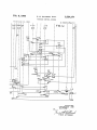
|:223
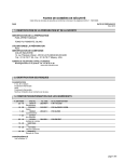
SA-PB
SA-PC
:i
222
SA~GH
’ (->
FIG.
INVENTORS.
aw. DAVISON AND
FIG.
BY
_
G.O.FERM
_
; THEIR ATTORNEY
Feb. 8, 1966
G. w. DAWSON ETAL
3,234,377
VEHICLE CONTROL SYSTEM
l ed
1y
F|l
l'6.
l9 1
liq11|
11 Sheets-Sheet 9
{CL
4/
93
{Il a|I.-li JIl
¢
lIIl'il A”
IlIl,II .1
1l‘I‘iI U
INVENTORS.
BY
G. VOV.DAV| SON
G .FERM
AND
THEIR ATTORNEY
ates atet
‘Vcc
3,22,34,37?
lantern-ted Feb. 8, 1956
1
2
VEHICLE CONTRQL SYSTEM
Gordon W. Davison and Glenn 0. Form, Rochester, N.Y.,
assignors to General Signal Corporation, a corporation
3,234,377
shunted by the vehicles traveling thereover, are utilized
to communicate various vehicle control codes, indicative
of existing advance conditions, ‘from the Wayside to the
vehicles, without requiring that these vehicle control codes
Filed July 14, 1961, Ser. No. 124,193
6 Claims. (Cl. 246-63)
direction of vehicle traf?c. As already mentioned, such
directional code transmission is necessary when coded
This invention generally relates to vehicle control sys
tems and more particularly pertains to the continuous
control of vehicles for opposite directions of traflic over a
proposed continuous vehicle control systems mentioned
above.
of New York
be transmitted in a certain direction for a corresponding
stretch of right-of—way.
The control system of the present invention has par
ticular utility in certain railway operations wherein it is
desirable to provide continuous control of the railway
vehicles, for opposite directions of vehicle travel, over a
right-of-way. For example, as embodied in the present
disclosure, the system of the present invention is par
ticularly suitable for governing the operation of railway
vehicles in opposite directions on a single track railroad
wherein stretches the single track are utilized for both di~
rections of vehicle travel.
In many of the previously proposed systems of con
energy on the track rails is utilized as in the previously
Another obvious advantage of utilizing wayside loop
circuits, for providing Wayside to vehicle control com
munication, is particularly evident in certain railway opera
tions, such as mining operations, wherein the railway
locomotives may at times pull and at other times push their
connected trains. By employing loop circuits, as proposed
in the present invention, wayside to locomotive com
munication is established independent of the locomotive
location with respect to its connected train whereas, in the
previously proposed control systems utilizing coded rail
current, the receiver coils are normally mounted on the
locomotives and therefore extra shifting means would be
required to shift the point of code reception between the
two ends of the vehicle, in order that the leading end
tinuous railway vehicle control, coded alternating current
is applied to the track rails to be inductively received by 25 would always inductively receive the coded rail currents
receiving coils mounted on the locomotive of a vehicle
traveling over the track rails.
The rate at which this
alternating current is coded, for application to the track
rails, is dependent upon the track and/ or traffic conditions
existing in advance of the vehicle. Such track and/or
tra?ic conditions are normally detected, in part, by track
relays, which when deenergized indicate that the associated
sections of the stretch of railway track are occupied and, in
part, by certain other detecting means conditioned, for
example, in accordance with the position of track switches
etc. The received control codes are then utilized to pro
vide automatic control of the vehicle throttle and brake
mechanism and/or to provide visual indication to the
normally transmitted in a direction opposite to that in
which the vehicle is travelling.
In the present invention, it is furthermore proposed to
provide means for detecting the davance conditions exist
ing along the stretch of right-of-Way in order that the
vehicle control coding shall be distinctive of such advance
conditions. However, since the system of the present in~
vention is intended for operation wherein either a train
shunt may not be reliable or no train shunt is involved,
occupancy detecting means independent of any train
shunt are provided, in accordance with the present inven
tion, to properly register the location of each vehicle on
the stretch of right-of-way so that proper restrictive con
engineman, of such advance conditions, through the me
trol may be communicated to any following vehicle. F or
dium of cab signalling.
40
example,
in the selected embodiment shown herein, check
When such previously proposed systems are utilized
in and check-out coils are disposed along the right-of
to provide control for both directions of tra?ic, over a sin
way to properly register vehicle occupancy along the
gle track, the direction of coding in the track rails; i.e. the
stretch of right-of~way. As mentioned previously, this
direction of code transmission, is necessarily controlled in
function was previously performed by track circuits and.
accordance with the desired direction of tra?ic. This is so
associated track relays which became decnergized when the
because a railway vehicle normally shunts the track rails
associated sections of railway track became occupied with
together and therefore, these coded alternating currents
a railway vehicle.
are transmitted in a direction opposite to that in which the
vehicle is traveling. This shunting of the track rails, by
the vehicle, is furthermore utilized, to deenergize the above 01
mentioned track relays, so as to provide restrictive con
trol for any following vehicle in order to maintain proper
spacing between the vehicles, and also prevents the recep
tion, on a following vehicle, of a control code intended
solely for the preceding vehicle.
It has been observed in certain railway operations,
however, such as mining operation, that the lightweight
cars used may fail to a?’ord the necessary degree of train
shunt required for proper operation of the previously pro
posed control systems mentioned above. Furthermore, in
certain other railway operations, such as a monorail sys
tern, a train shunt may not be involved. Therefore, the
need exists for a continuous control system to control both
directions of railway tra?ic wherein a shunting of the track
rails, by the vehicles, is not required for proper operation
of such a continuous control system.
Without attempting to de?ne the exact scope of the
present invention, it is proposed in accordance herewith to
provide a continuous control system, for controlling the
operation of vehicles in opposite directions of a stretch
of right-of-way, wherein wayside loop circuit means, not
In order that the vehicle control codes transmitted from
the wayside to a vehicle will be indicative of conditions
existing along the right-of-way, in advance of such vehicle,
it is further proposed, in accordance With the present in
vention, to provide certain means conditioned in accord—
ance with the preselected direction of vehicle traffic over
the right-of-way which select control coding, distinctive of
advance conditions along this direction, to be communi~
cated to the vehicle While it is traveling over the stretch
of right-of-way. For example, in the selected embodiment
shown herein, magnetic stick type relays are employed
which assume one or the other of their operating positions
in accordance with the desired direction of tral?c on a
single track railroad and, being so positioned, cause the
vehicle control codes communicated from the wayside to
the railway vehicles, to be that which is distinctive of the
conditions existing in advance of such railway vehicles.
In view of the above discussion, one object of the
present invention is to provide a continuous control system
for controlling the operation of vehicles in opposite direc
tions over a stretch of right-of-way, wherein wayside loop
circuits, not subjected to vehicle shunting, are utilized to
communicate vehicle control codes, from the wayside to
vehicles traveling over the stretch of right-ot-way.
3,234,877
3
A further object of the present invention is to provide
4
these tracks would also be provided with loop circuits,
for wayside to vehicle communication, similar to those of
directive means, conditioned in accordance with the pre
the illustrated stretch of single track. Similarly, track
selective direction of vehicle traf?c over the stretch of
sections MB and SB are the ?rst track sections to the right
right-of-way, for causing the vehicle control codes, com
or eastbound from the OS section for track switch SW2
municated between the wayside and the vehicles traveling
of FIG. 1G.
thereover, to be those distinctive of the existing conditions
Without attempting to limit the scope of the present
in advance of such vehicles.
invention, it is intended in this selected embodiment that
A further object of the present invention is to properly
the following vehicle controls and/ or indications are
register the location of vehicles on the stretch of right-of
way, without relying on such vehicle shunting, whereby 10 involved in accordance with various control code rates
utilized—
proper restrictive vehicle controls are communicated to
any following vehicles.
Code rate:
Vehicle control
Other objects, purposes, and characteristic features of
180 ____________ __ High speed.
the present invention will in part be obvious from the
75 ______________ _. Low speed.
accompanying drawings, and in part pointed out as the 15
371/2 ____________ _. Service brake application.
description of the invention progresses. In describing
No code ________ __ Emergency brake application.
the invention in detail, reference will be made to the
Obivously, both more and different code rates may be
accompanying drawings in which:
used, dependent upon the amount of actual vehicle con
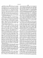
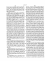
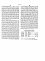
FIGS. 1A through 11. (xcept that FIG. 11 has been
trol and/ or indication required in practice, and the use
20
omitted) illustrated a stretch of single track railroad
of the four codes mentioned above, for providing four
equipped in accordance with one embodiment of the
distinct vehicle controls and/or indications is merely to
present invention.
facilitate in the present disclosure of the invention.
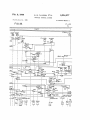
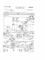
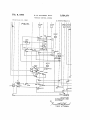
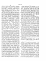
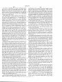
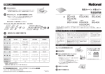
FIG. 2 illustrates diagrammatically certain vehicle car
In order to render the coding applied to each loop cir
ried apparatus associated with the same embodiment of
cuit
dependent upon the conditions in advance of a rail
25
the present invention.
way vehicle, certain directional means have been provided
FIG. 3 is an arrangement diagram illustrating the proper
which register the desired direction of tra?ic, called for
arrangement of FIGS. 1A through 1L (with FIG. 11
by the control o?ice, for each distinct move on the illus
omitted).
trated track layout. The condition of these directional
In order to simplify the illustration in the drawings and
then determines whether vehicle control coding
facilitate in the explanation of the fundamental character 30 means
for an eastbound or westbound move should be applied
istics of the invention, various parts and circuits have been
to the illustrated wayside loop circuits TC, for communi~
shown diagrammatically in accordance with conventional
cation to a railway vehicle traversing the illsutrated track
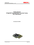
symbols. Thus, the symbols (BX) and (NX) are em—
layout. Thus, in the selected embodiment shown, mag
ployed to indicate the opposite terminals of a suitable
netic stick type relays TF are provided which are selec
source of alternating current and the symbols (+) and 35 tively energized with current of one polarity or the other,
(—) are employed to indicate the opopsite terminals
to operate them to either one or the other of their two
of a suitable source of direct current for the energization
possible operating positions, in accordance with the desired
of the illustrated relays.
direction of travel on the illustrated track layout. Being
Referring now to the accompanying drawings, a right
so positioned, these magnetic stick relays TF then cause
40
of-way is shown, in the form of a portion of single track
the conditions in advance of a vehicle to determine the
railroad having a stretch o fsingle track extending be
code rate to be applied to each of the illustrated way
tween passing siding A (FIG. 1A) and passing siding B
(FIG. 1G). A track switch SW is then provided at each
siding for selectively routing railway vehicles for either
main line or siding moves, dependent upon supervisory
switch controls transmit-ted from a control of?ce (not
shown).
The illustrated track layout is furthermore divided
into distinct track sections formed by the positioning of
wayside check-in and check-out coils CI and CO, to be
described hereinafter, and are provided with wayside loop
circuits TC which communicate vehicle control informa
tion, from the wayside to the railway vehicles as they
travel over the associated sections of the illustrated track
layout.
More speci?cally, the illustrated stretch of single track,
extending between passing siding A and B, includes track
sections 1T, 2T and 3T having associated wayside loop
circuits 1TC, 2TC and 3TC respectively. Extending
from each end of this illustrated single track is the usual
OS detecting section, provided to detect when a railway
vehicle is adjacent the associated track switch, to prevent
operation of the switch under a vehicle. In order that
vehicle control code may be communicated to vehicles
traveling over the illustrated track switches, these OS
sections are also provided with certain wayside loop
circuits TC. Referring now to FIGS. 1A and 1B, the
OS section associated with track switch SW1 is provided
with wayside loop circuits lATC, ZATC and 3ATC,
whereas the OS section for track switch SW2 is provided
with wayside loop circuits lBTC, 2BTC and 3BTC of
FIGS. 1F and 1G. To the left or westbound from the
OS section associated with track switch SW1, the main
and siding tracks of siding A include track sections MA
and SA respectively and it should be understood that
side loop circuits TC. It should be furthermore pointed
out that these relays TF remain in their last operated
position when the energizing current to their respective
windings has been removed.
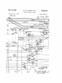
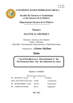
In order to detect the location of the railway vehicles
on the illustrated track layout, without relying on train
shunt, inert tuned vehicle detecting coils CI and C0
are positioned so as to divide the track layout into sec
tions and are actuated, by certain vehicle carried ap
paratus, to be described hereinafter, to respectively de
tect when a vehicle is checking into and out of the illus
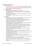
trated track sections. For example, referring to FIGS.
1C, 1D and 1E, westbound vehicles are checked into
track section 2T at coil 2T-LCI of FIG. 1B, and, are
checked out at coil 2T*LCO of FIG. 1C. Similarly,
eastbound vehicles are checked in and out of sect-ion
2T at coils 2T—RCI and 2T—RCO respectively, of FIGS.
1C and 1E respectively.
Associated with each of the illustrated track sections
is an occupancy detecting relay TR which becomes de
energized, as will be described hereinafter, whenever
the associated track section -is occupied by a railway
vehicle, as detected by the check-in and check-out coils
CI and CO. This occupancy detecting relay TR is then
utilized to perform certain functions of the conventional
track relay without requiring the use of track circuits;
i.e. without requiring that a railway vehicle shunt the
rails of a section together. As previously mentioned,
this is desirable in applications where a train shunt is
not involved, or in certain railway operations wherein
lightweight railway cars are utilized and the degree of
shunting afforded by such lightweight cars may be in
suf?cient to properly register the location of a railway
3,234,377
5
vehicle and therefore may be insufficient for proper
operation of a control system. These occupancy de
tecting relays TR are thus utilized to initiate the vehicle
control coding of the associated wayside loop circuits
Certain wayside signals have been shown in the ac
companying drawings, at the usual locations, for con
trolling the respective vehicle movements at sidings A
and B. More speci?cally, wayside signals IRA or IlRB
TC and furthermore are utilized to insure proper re
of FIG. 1A control the left hand or eastbound entrance
strictive controls for any following moves, in order to
maintain proper spacing between the various vehicles
onto the illustrated stretch of single track, for main line
and siding moves respectively, whereas signal 1L of FIG.
utilizing the illustrated track layout.
1C controls the westbound departure of railway vehicles
Referring now to FIG. 2 of the accompanying draw
from the illustrated stretch of single track. Similarly,
ings, certain vehicle carried apparatus is illustrated for 10 signals ZLA and ZLB of FIG. 16 control the right hand
operation with the wayside apparatus, just described, and
or westbound entrance of vehicles onto the illustrated
in accordance with vehicle control codes communicated
from the wayside to the vehicles, by the above mentioned
stretch of single track, whereas signal 2R of FIG. 1E
controls the eastbound departures from the illustrated
stretch of single track, toward the siding B.
loop circuits TC. More speci?cally, receiver coils RC
inductively pick up the coding present in the loop cir 15
cuits, as a vehicle travels over the associated track sec
These various wayside signals are then cleared in ac
codance with supervisory control established by a
tions, and these received control codes are then decoded
central control office such as is utilized in a centralized
and utilized by the vehicle control apparatus VCA,
shown in FIG. 2, to control operation of the railway
vehicle. As previously mentioned, it is intended here
traffic control system or the like. Thus, referring to
FIGS. 1] and 1K, the usual signal clearing relays GZ
are employed for selectively clearing the illustrated way
that such vehicle control apparatus VCA may be of any
suitable form which provides automatic control of the
side signals. Furthermore, although the energizing cir
cuits by which each of the illustrated wayside signals
vehicle throttle and brake mechanism and/or which
are cleared have not been shown in detail, in the accom
provides visual indication to an engineman of such
panying drawings, it is assumed here that these various
designated vehicle controls, in accordance with the re 25 wayside signals are properly interlocked, in accordance
ceived control codes. It will be noted that, since the
illustrated wayside loop circuits TC are not shunted
by a railway vehicle traveling on the illustrated track
layout, receiver coils RC of FIG. 2 can inductively re
with usual signalling practice well known to those skilled
in the art, so that two opposing signals cannot be cleared
at the same time.
However, since the system of the present invention is
ceive the vehicle control codes communicated by loop 30 intended for governing of the operation of unmanned
circuits TC, irrespective of their location on a railway
vehicle. As mentioned previously, this is desirable in
certain railway applications wherein a locomotive may
sometimes push and at other times pull its connected
train.
A railway vehicle, in accordance with the selected em
bodiment, furthermore carries certain transmitting units,
at its respective ends, each of which transmits a fre
quency distinctive of that particular end of the vehicle.
Thus, oscillator unit OH is mounted on the illustrated
as well as manned vehicles, it should be obvious, in the
case of unmanned vehicle control, that no Wayside sig
nalling is required and that the above mentioned exit
and entrance control is then accomplished by applying
the proper vehicle control coding to the appropriate way
side lope circuits, and therefore, the directional mag
netic stick relays TF, shown in the accompanying draw~
ings, are properly interlocked so that only a single direc
tion of traf?c can be established, at any given time, on
the illustrated stretch of single track. Such control for
vehicle and transmits a frequency F1 which is distinctive
unmanned vehicles will be discussed in detail hereinafter.
In view of the above, it should therefore be understood
vehicle carried oscillator unit OT transmits a frequency
at this time that the illustration of these wayside signals
F2 which is distinctive of the tail end of the illustrated
is merely to facilitate in the present disclosure of the
vehicle. This frequency Fl, distinctive of the head end 45 invention rather than to limit the number of forms which
it ‘may assume.
'
of the illustrated railway vehicle, is then applied to trans
mitting coil VH to selectively actuate the appropriate
Iaving thus described the general organization of the
check-in coils CI (tuned to frequency F1) as the head
selected embodiment of the present invention, a detailed
discussion of the operation of the illustrated apparatus
end of the vehicle passes these wayside checlein coils
of the head end of the illustrated railway vehicle, while
during movement of the railway vehicle in the illus- '
trated track layout. Similarly, frequency F2 distinctive
of the tail end of the illustrated railway vehicle, is ap
plied to transmitting coil VT for selectively actuating
appropriate check-out coils CO (tuned to frequency F2)
as the tail end of the illustrated vehicle passes these
wayside check-out coils. It is of course assumed here
that a railway vehicle, traveling in a given direction on
the illustrated track layout, will only actuate the check
in and check-out coils CI and CO associated with that
direction and not actuate the corresponding coils for
the opposite direction of traffic. Furthermore, although
only two frequencies F1 and F2 have been discussed,
for identifying the respective ends of the railway vehicles,
will now be set forth.
NORMAL CONDITIONS
Before beginning a detailed description of the system
operation, it is ?rst desirable to establish the normal
operating conditions for the illustrated circuit organiza
tions Thus, the accompanying drawings illustrate those
conditions which are assumed to be normal with no
vehicles occupying the illustrated track layout, no vehicle
moves presently being called for by the supervisory con
trol o?‘ice and the directional magnetic stick relays TF
in that position corresponding to the last direction of
trai?c assumed to have taken place on the illustrated
track layout.
for both direction of trat?c, it should be understood
In the accompanying drawings, it will be noted that
65
that, if desired, frequencies F1 and F2 could be utilized
each of the illustrated track sections is provided with
for identifying the respective ends of the vehicles for
substantially the same relay circuit organization includ
ing relays PA, PB, PC, TR and CO. In order to illus
trate how the normal operating conditions are estab
spective ends of the vehicles for the opposite direction 70 lished for the illustrated circuit organizations, a detailed
of vehicle traffic. In this latter case, the westbound
description for establishing these normal operating con
checlein coils might be tuned to frequency F1, the west
ditions will be set forth for the apparatus associated with
bound check-out coils might be tuned to frequency F2
track section 2T of FIG. 1D, and, since all the other
and the eastbound check-in and check-out coils might
track sections are similarly equipped, the establishment
then be tuned to frequencies 4 3 and F4 respectively.
of the normal operatingaconditions for these other track
one direction of vehicle traffic and additional frequencies,
such as F3 and F4, could be utilized to identify the re
3,234,377
7
8
sections should be obvious from the description for track
section 2T.
Referring now to FIG. ID of the accompanying draw
favorable for the desired vehicle move; i.e. the route‘is
available and the proper traffic direction is established.
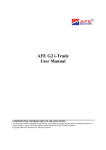
Referring to FIG. 1], relays IRAS and lLAS are also
provided with similar stick circuits and are normally
ings, relay 2T-PA is normally maintained in its picked
maintained picked up by those stick circuits completed
through back contacts of the associated signal clearing
relays IRGZ and lLGZ respectively.
and lT-RCOR respectively, back contacts 12 and 13 of
Referring to FIG. 1K, with relays 2LAS and 2RAS
relays 2T~LCIR and 3T-LCOR respectively, front con
picked up, as described above, relay 2L is also normally
tact 15 of relay ZT-PA, and to (—). Relay 2T-PB
is then maintained normally picked up through front 10 picked up by a circuit extending from (+), through
front contacts 36, 37 and 38 of relays 2RAS, ZLAS and
contact 16 of relay 2T-PA, and, relay 2T-PC is also
B—TR respectively, check contact 38a of time element re
normally picked up through front contact 17 of relay
2T-PB. With relays 2T-PA, 2T-PB and 2T-PC thus
lay ZTE, and to (—). Furthermore, relay ZLS is also
normally picked up by a circuit extending from (+),
normally picked up, occupancy detecting relay 2T~TR
is also normally picked up by a circuit extending from 15 through front contact 39 of relay B-TR, front contact
40 of relay 2L, and to (—). This relay 2LS controls
(+), through the normally closed contacts 18 of push
the locking and unlocking of track switch SW2, of FIG.
button 2T—MRP, front contacts 19, 20 and 21 of relays
1G; i.e., when relay 2L8 is in its picked up position it
2T—PA, 2T-PB and 2T-PC respectively, and to (—).
unlocks track switch SW2 so that it may be positioned
As mentioned earlier, this occupancy detecting relay
up position by a stick circuit extending from (+),
through back contacts 10 and 11 of relays ZT-RCIR
2T-TR is utilized to perform functions similar to those 20 in accordance with the desired routing of vehicles at
siding B, and, when relay 2LS is in its deenergized posi
of the conventional track relay without requiring the use
tion it locks track switch SW2 to prevent any change
of track circuits; i.e. without requiring a shunting to
in the position of this track switch SW2. Similarly, re
gether of the track rails of a track section.
lays IL and iLS of FIG. 1] are also normally picked up
The OS sections associated with each end of the illus
trated stretch of single track are provided with corre 25 by similar circuits to those just described ‘for relays 2L
sponding PA, PE, PC, TR and CO relays. Of these,
and 2LS, and relay lLS performs the similar locking
relays PB, PC and TR are normally maintained in a
and unlocking control of track switch SW1 of FIG. 1A.
picked up position by circuits similar to those already
As previously mentioned, the illustrated directional
magnetic stick relays TF remain in their last operated
position, corresponding to the last direction of traf?c
described for track section 2T of FIG. 1D.
However,
the circuit by which the relays PA, associated with the
on the illustrated track layout. Assuming now that the
OS sections, are normally picked up is somewhat differ
last tra?ic on the illustrated track layout was in the east
ent and extends, for example, for relay‘ B—PA of FIG.
bound direction, or left to right in the accompanying
1F, from (+) in FIG. 1L, through back contact 22 of
drawings, each of the illustrated relays TF are in their
relay B—SLCIR, back contact 23 of relay SB—LCOR,
along wire 24 between FIGS. 1L and 16, back contacts 35 dropped away position corresponding to this assumed
previous eastbound tra?ic. This relay registration of a
25 and 26 of relays B-MLCIR and MB~LCOR respec
tively, along wire 27 between FIGS. 16 and IF, back
desired direction of traf?c, by selective energization of
contacts 28 and 29 of relays B-RCIR and 3T-RCOR
respectively, front contact 30 of relay B—PA, and to (—).
the directional magnetic stick relays TF, and the retain
ment of these relays TF in their last operated position,
It should be pointed out at this time that the above
discussed normal conditions are automatically assumed
will be described in detail hereinafter.
Since eastbound tra?ic was the last to utilize the illus
by the wayside circuit organization, associated with the
trated track layout and since the directional magnetic
stick relays TF are therefore in their dropped away posi
tion, the relays YH and GH associated with each of the
establish these normal operating conditions, when plac 45 illustrated track sections are then selectively energized
in accordance with the conditions existing to the right
ing the system in service, manual push buttons MRP
various sections when the sections are unoccupied, as
will be discussed hereinafter. However in order to
have been provided at each of the illustrated track sec
of or eastbound from, that track section.
tions for initially picking up the associated PA relay
ci?cally, the eastbound energizing circuits for the relays
More spe
YH and GH, associated with each of the illustrated track
which in turn cause the remaining relays associated with
a given section to assume their normal operating condi 50 sections, extend through back contacts of the associated
tions just described. Thus, referring to FIG. 1D, relay
ZT-PA is picked up, when placing the apparatus for
track section 2T into service, by the depression of push
button 2T-MRP which completes an energizing circuit
for relay ZT-PA extending from (+) in FIG. 1D,
through contacts 31 of push button 2T-MRP, and
to (—).
Referring now to FIGS. 1] and 1K of the accompany
ing drawings, each of the illustrated signal locations is
provided with approach relays LAS and RAS which are
normally picked up until the associated signal is cleared
by the picking up of an associated signal clearing relay
GZ from the control office. Thus, referring to FIG.
1K, relay 2LAS is normally maintained in a picked up
position by a stick circuit extending from (+), through
back contact 32 of relay 2LGZ, front contact 33 of
relay 2LAS, and to (—). Similarly, relay 2RAS of
FIG. 1K is normally maintained in a picked up posi
tion by a stick circuit extending from (+), through back
contact 34 of relay 2RGZ, front contact 35 of relay
2RAS, and to (-—). Furthermore, approach relays
directional magnetic stick relay TF, whereas the west
bound energizing circuits for these relays YH and GH
extend through front contacts of the associated direc
tional magnetic stick relay TF.
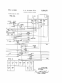
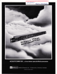
The various code rates utilized in the selected embodi
ment of the present invention are developed by code
transmitters CT associated with each of the illustrated
track sections. Dependent upon the positions of the YH
and GH relays, associated with a given track section,
60 code repeater relay CP is then selectively energized at
either a 180, 75 or 371/2 code rate to cause energization
of the loop circuit TC, associated with that track section,
in accordance with the advanced conditions existing along
preselected direction traiiic. However, it wil be noted
in the drawings that the energizing circuits for the vari
ous code repeater relays CP are completed through a back
contact of the associated occupancy detecting relay TR
so that the selected code rate is only applied to the way
side loop circuits TC, when the associated track sections
become occupied.
More speci?cally, for a given track section, if relays
2LAS and 2RAS are also provided with additional stick
circuits, to be described hereinafter, which insure that
these relays are dropped away, upon pick up of the as
YH and GH are both dropped away, the energizing cir
cuit for the associated code repeater relay CP will be
sociated signal clearing GZ relay, only if conditions are
to the associated loop circuit TC.
conected so as to select a 371/2 code rate to be applied
However, if relay
3,234,377
11
12
relay ZT-LCIR then returns to its normal deenergized
position, relay ZT-I’A remains in its present dropped
away position until this Westbound vehicle has been
properly checked out of track section 2T, as will be de
scribed hereinafter. Furthermore, when relay 2T—LCIR
drops away, the above described stick circuit for relay
2T—PB is interrupted at front contact 6% of relay 2T-LCIR
and therefore relay 2T-PB is dropped away.
Relay
for
set
the
the
a westbound vehicle, a similar discussion will now be
forth for an assumed eastbound vehicle entering at
left-hand end of track section 2T of FIG. 1D. When
head end of this assumed eastbound vehicle passes
wayside check-in coil ZT-RCI of FIG. 1C, relays 2T
RCIR of FIG. 1D is momentarily energized to open its
back contact 10 and relay 2T-PA is now dropped away
to initiate the check-in process. Relay 2T-PB, however,
2T-PC however is now maintained in its normal picked
is maintained ‘in its normal energized position by a stick
up position by a stick circuit extending from (+), 10 circuit which now extends from (+), through front con
through back contact 59:: of relay ZT-RCIR, back con—
tact 7 3 of relay ZT-RCIR, front contact 61 of relay 2T
tact 68 of relay 2T—LCIR, back contact 78 of relay
PB, and to (—).
2T—PA, front contact 71 of relay 2T-PC, and to (—).
In a similar manner to that set forth in describing
The purpose of this relay ZT-PC is to remove any code
the operation for a westbound vehicle, when relay 2T—
from loop circuit ZTC in the event that a following vehicle 15 PA is thus dropped away, occupancy detecting relay 2T
enters track section 2T before preceding vehicle is properly
TR also closes its back contacts and thereby completes
checked out. This operation will be described in detail
the energizing circuit for relay 2T—CP, extending from
hereinafter.
(+), through back contact 62. of relay ZT-TR, front
Assuming now that this westbound vehicle passes way
contact 63 of relay ZT-PC, through front contacts 64
side coils lT-LCI, relay lT-LCIR of FIG. 1C is momen
and 65 of relays 2T-YH and ZT-GH respectively (as
tarily energized to open its back contact 72 and thereby
suming clear advance conditions east of track section
interrupts the existing stick circuit for relay 1T-PA to
initiate the checking in, of this westbound vehicle, at
track section 1T of FIG. 1C.
In a similar manner to
2T), through front contact 66 of code transmitter 18OCT,
and to (—). This 180 code rate energization of code
repeater 2T-CP then causes the 180 code rate, distinctive
that just described, loop circuit ITC is then energized at 25 of the assumed clear condition in advance of track sec
a vehicle control code rate depending the existing operat—
tion 2T, to be applied to loop circuit lTC to control the
ing position of relays 1T—YH and 1T—GI-I, which in turn
eastbound vehicle.
are dependent upon the advance conditions existing to the
Referring to FIG. 1D, it will be noted that back con
left or westbound from track section 1T.
tact 11 of relay lT-RCOR is connected in series in the
Assuming now that these advance conditions are such 30 normal stick circuit for relay 2T~PA. This insures that
that the assumed westbound vehicle may continue over
the eastbound vehicle will be checked into track section
the illustrated stretch of single track, wayside check out
2T (when the tail end of the vehicle passes way side
coil 2T—LCO of FIG. 1C will be momentarily actuated,
coil lT-RCO) in the event check-in coil relay ZT-RCIR
as the tail end vehicle coil VT on the westbound vehicle
fails to properly register the passing of the head end of
passes, to momentarily energize the associated relay 2T
the eastbound vehicle. Similarly, back contact 13 of
LCOR of FIG. 1C. When this occurs, check-out relay
relay ST-LCOR is connected in the normal stick circuit
2T—CO of FIG. 1]) is now energized by a circuit extend
of relay ZT-PA and serves a similar purpose during west
ing from (+) in FIG. 1C, through back contact 73 of
bound moves.
relay 1T-—PA, front contact 74 of relay 2'I‘—LCOR, along
In substantially the same manner as was previously
wire 75 between FIGS. 1C and 1D, through front con 40 set forth for the assumed westbound vehicle, after this
tact 76 of relay 2T—PC, and to (—). This picking up
assumed eastbound vehicle has been properly checked in
of check-out relay 2T—CO properly checks the assumed
to track section 3T of FIG. 1B, and, the tail end of the
westbound vehicle out of track section 2T and thereby
vehicle passes wayside check-out coil 2T—RCO of FIG.
causes relay 2T—PA to pick up by a circuit extending
1E, check-out relay 2T—CO of FIG. 1D is momentarily
from (+), through back contacts 143, 11, 12 and 13 45 energized by a circuit extending from (+) in FIG. 1E,
of relays 2T—RCIR, 1T—RCOR, ZT-LCIR and 3T~
through back contact 79 of relay 3T-PA (which was
LCOR respectively, front contact 77 of relay ZT-CO,
dropped away when the eastbound vehicle was checked
and to (—). Once relay ZT-PA is thus picked up, it
into track section 3T), through front contact 80 of relay
will be maintained in its normal picked up position, even
2T—RCOR, along wire 81 between FIGS. 1E and 1D,
though check-out relay 2T-CO is subsequently dropped
through front contact 76 of relay 2T-PC, and to (—).
away, by the illustrated stick circuit which includes front
contact 15 of relay 2T—PA in multiple with front contact
77 of relay 2T—CO. Relay ZT-PB is now also returned
In exactly the same way as that previously described for
restoring the circuit organization of track section 2T to
its normal condition, relays ZT-PA, 2T-PB and ZT-TR
to its normal energized position by the previously de
are again returned to their normal picked up positions,
scribed energizing circuit including front contact 16 of 55 to properly check the assumed eastbound vehicle out of
relay ZT-PA. By referring to FIG. 1D it will be noted
that, until relay 2T~PB is thus picked up, the energizing
stick circuit for relay ZT-PC is interrupted at back con
tact 70 of relay ZT-PA and it is thus assumed here that
the drop away time of relay 2T-PC is su?icient to bridge
that time interval between the picking up of relay 2T
track section 2T, upon this picking up of check-out relay
ZT-CO.
Furthermore, the subsequent picking up of
PA and the subsequent picking up of relay ZT-PB, so
occupancy detecting relay ZT-TR once again removes
the vehicle control coding from loop circuit ZTC.
GENERAL OPERATION
In order to point out how the system of the present
that relay 2T~PC is now also maintained in its normal
invention provides for controlling both following and
picked up position by the previously described energizing
opposing vehicle moves, it will now be assumed, with
circuit which includes front contact 17 of relay 2T-PB. 65 the illustrated circuit organization returned to its illus
With relays ZT-PA, ZT-PB now returned to their
trated normal condition, that the control office (not
normal picked up positions, occupancy detecting relays
shown) wishes to condition the illustrated track layout
2T—TR is now also returned to its normal picked up posi
for a westbound main line move for a railway vehicle
tion by the previously described energizing circuit, includ_
approaching wayside signal ZLA of FIG. 16. Initially
ing contacts 18 of push button 2TwMRP and front con 70 then, the control o?ice sends out a switch control trans
tacts 19, 20 and 21 of relays ZT-PA, 2T-PB and 2T-PC
mission for positioning track switch SW2 of FIG. 16
respectively, and thereby opens its back contact 62 to re
to its normal position, and, after track switch SW2 has
move the coding from wayside loop circuit ZTC.
been operated to its full normal position, switch corre
spondence relay ZNWC of FIG. 1F is picked up as illus
Having thus described the typical operation of the
circuit organization associated with track section 2T,
trated in the accompanying drawings.
3,234,377
‘ill
9 .
YH is picked up and relay GE is dropped away, the en
ergizing circuit for the code repeater relay CP will be
circuits, for the code repeater relays CP (not shown)
connected so as to select a 75 code rate for the associated
associated with track sections SA and MA of FIG. 1A,
for 371/2 code rate energization.
loop circuit TC. Finally, if both relays YH and GH are
picked up, the energizing circuit for code repeater relay
CP, utilized in the selected embodiment, have their re
As previously pointed out, the code repeater relays
CP will be connected so as to select a 180 code rate for
spective energizing circuits normally selected by the relays
the associated wayside loop circuit TC. In addition, al_
though no energizing circuits have been illustrated for
YH and GH, but, the actual energization of the relays
Since track switch SW2 of FIG. 1G is unlocked, by
the previously described pick up of relays 2L and 2L8,
although only two relays (YH and GH) are illustrated
for selecting the vehicle control coding for each loop
circuit, it is obvious that, if required, additional code
selecting relays could also be provided, to obtain addi
CP occurs only while the associated track sections are
the various code transmitters CT, shown in the accom
occupied, as detected by occupancy detecting relays TR.
panying drawings, it is assumed that these code trans~ 10 Thus, the vehicle control codes are applied to the way
mitters CT are continuously energized to transmit their
side loop circuits TC only when needed for controlling
respective code rates.
railway vehicles. Furthermore, as mentioned previously,
and therefore is not in condition for train movements
thereover, relays B—YH and B-GH are both deenergizedv
More speci?cally, the eastbound energizing circuit for
tional vehicle controls and/ or indications.
relay B-YH; i.e. the circuit by which relay B-YH is
TYPICAL TRACK SECTION OPERATION
energized for eastbound tratlic, is interrupted at back
Since each of the illustrated track sections has asso
contacts 41 and 42 of relays 2L and ZLS respectively.
ciated with it circuit apparatus similar to that of all other
With relay B-YH thus dropped away, the eastbound
sections, the typical operation of the circuit apparatus for
energizing circuit for relay B-GH is also interrupted at
track section 2T of FIG. ID will now be set forth in
front contact 43 of relay B-—YH. As previously men
detail for both east and westbound vehicle moves, in order
tioned, with relays B-YH and B-GH both dropped away,
the energizing circuit for code repeater relay B-CP of 25 to facilitate in the present disclosure.
Neglecting, for the time being, the operation of direc
FIG. 1F is normally set for 371/2 code rate energization.
tional magnetic stick relays TF, it will be assumed that
Relays ST-YH and 3T-GH, associated with track sec
the various other relays (PA, PB, etc), associated with
.tion 3T of FIG. iii, are also both dropped away, the
section 2T, are in their respective normal operation posi
eastbound energizing circuit for relay 3T-YH being
opened at front contact 4-4 of signal clearing relay ZRGZ 30 tions shown in the accompanying drawings. When the
(see FIG. 1F), whereas the eastbound energizing circuit
head end of a Westbound vehicle now passes wayside
check-in coil 2T—LCT of FIG. 1E, and vehicle carried
coil VH of FIG. 2 thereby causes momentary picking
relay 3T—YH. Therefore, the energizing circuit for code
up of the associated relay ZT-LCIR of FIG. 1D, relay
repeater 3T-CP is also normally set for 37%. code rate
energization.
35 T-PA is dropped away by the opening of back contact
11.2 of relay ZT-LCIR. Although the above described
Relay ZT-YH of FIG. 1D, however, is energized at
for relay 3T-Gl-l is interrupted at front contact 45 of
this time by circuit extending from (—|—) in FIG. 1E,
through front contact 4-6 of relay 3T-TR, along wire 47
between FIGS. 1E and 1D, through back contact as
of relay ZT-TF, and to (—). However, relay 2T-GH
is'not energized at this time due to the interruption of its
energizing circuit at front contact 49 of relay 3T-YH
of FIG. 1E. With relay ZTJ’H picked up and relay
ZT-Gl-l thus dropped away, the energizing circuit of code
repeater relay ZT-CP of FIG. 1D is normally set for 75
code rate energization.
Relays lT-YH and lT-GH of FIG. 1B are both en
ergized at this time; relay lT-YH being energized by
a circuit extending from (+) in FIG. 1D, through front
contact 59 of relay ZT-TR, along wire 51 between FIGS.
ll) and 1C, through back contact 52 of relay 1T—TF,
and to (—), and, relay llT-GH being energized by a cir
cuit extending from (+) in FIG. 1D, through front con
tact 53 of relay ZT-YH, along wire 54 between FIGS.
1D and 1C, through front contact 55 of relay ltT-YH,
back contact 56 of relay lT-TF, and .to (—). The en
ergizing circuit for code repeater relay lT-CP is there
normal energizing circuit for relay 2T—PB is also inter
rupted by the subsequent opening of front Contact 16 of
relay ..T—?A, relay ZT-PB is now maintained in its
normal picked up position by a temporary stick circuit
which extends from (+), through back contact 59a of
relay 2T-—RClR, front contact 60 to relay ZT-LCIR, front
contact 61 of relay ZT-PB, and to (—). However, this
dropping away of relay ZT-PA does interrupt the ener
gizing circuit for occupancy detecting relay 2T—TR, at
front contact 19 of relay ZT-PA, to properly check the
westbound vehicle into track section 2T.
Dependent upon the existing positions of relays ZT-YH
and ZT-GH, which are positioned in accordance with
the advance conditions to the left or westbound from
track section 2T, relay 2T—CP is now energized to apply
one of the above mentioned code rates to the wayside
loop circuit ZTC.
For example, if it is assumed that
conditions are clear westbound from track section 2T;
vi.e. relays ZT-YH and 2T—GH are both picked up, relay
2T—CP is energized at a 180 code rate by a circuit ex
tending from (-1-), through back contact 62 of relay
ZT-TR, front contact 63 of relay ZT-PC which was not
fore normally set at 180 code rate energization.
dropped away when the westbound vehicle entered track
Although the track conditions eastbound or to the
right of the OS section for track switch SW1 are clear; 60 section 2T, front contacts 64 and 65 of relays 2T-YH
and 2T-GH respectively, front contact 56 of code trans
i.e. relays llT-YH and llT-GH are both picked up, relays
mitter mil-CT, and to (—). This coded energization of
A-YH and A-GH of FIG. 1B are not energized at this
code repeater ZT-CP causes a 180 code rate to be applied
time since track switch SW1 is normally unlocked by
to loop circuit 2TC by a circuit extending from (BX),
the previously discussed picking up of relays 1L and 11S
of FIG. 1}. That is, the pick up circuit for relay A—YH 65 through front contact 67 of relay ZT-CP, through way
is interrupted at back contacts 57 and 58 of relays 1L
side loop circuit ZTC, and to (NX .
and 1L5 respectively, whereas the energizing circuit for
relay A-GH is interrupted at front contact 59 of relay
A-YH. Therefore, the energizing circuit for code re
peater relay A-CP is normally set for 371/2 code rate
energization. Similarly, since track switch SW1 is un
locked and signal clearing relay lRGZ of FIG. 1B is
deenergized, relays MA—YH and MA—GH of FIG. 1A
and relays SA—'YH and SA-GH of FIG. 1H are also
previously, the reception of this 180 code rate, on the
vehicle, via receiver coils RC of FIG. 2, causes the west
bound Vehicle occupying track section 2T to either speed
up to or continue at its nominal high speed setting in
accordance with the assumed clear conditions westbound
from track section 2T.
As mentioned previously, relay ZT-LCIR is but mo
mentarily energized as the head end of the assumed west
As mentioned
deenergized and thereby normally set up the energizing
bound vehicle passcs wayside coil ZT-LCI, and, when
3,234,377
In order to establish this desired westbound traiiic
traveling at too fast a speed to be safely brought to a com
direction, the control office now sends out a signal clear
plete stop short of wayside signal 2LA. Thus, if relays
ZLAS, 2L and ZLS have been deenergized, by the pick
ing up of signal clearing relays ZLGZ, and, if the control
office operator then returns signal clearing relay ZLGZ
to its normal deenergized position, relay ZLAS cannot be
immediately picked up to unlock track switch SW2, until
ing control to pick up relay ZLGZ of FIG. 1K. Even
though back contact 32 of relay ZLGZ is now opened,
approach relay ZLAS is maintained picked up, until the
proper direction of traii‘ic is established, by an additional
stick circuit including back contact 82 of directional
magnetic stick relay B—TF.
the timing operation of time element relay 2TB has been
This picking up of signal clearing relay ZLGZ, how—
completed.
ever, also completes an energizing circuit for trat?c relay
ZLF of FIG. 1K extending from (+), through front con
tact 85 of relay ZLGZ, and to (-—). The subsequent
picking up of tra?ic relay ZLF then causes directional
More speci?cally, if signal clearing relay
ZLGZ is dropped away by the control office, with relay
ZLAS also dropped away, relay ZTE is then energized by
a circuit extending from (-1-), through back contact 32 of
relay ZLGZ, front contact 97 of relay B—TR, back con
magnetic stick relays B—TF, 3T—TF, 2T-TF, lT-TF and
tact 98 of relay ZLAS, and to (—). However, ‘as soon
A-TF of FIGS. 1K, 1E, 1D, 1C and 13' respectively to 15 as time element relay 2TB completes its preselected tim
each assume their picked up or westbound position by
ing operation and closes its front contact 99, relay ZLAS
energizing them with that polarity of current required for
can be picked up, to unlock track switch SW2, by a cir
pick up of these directional magnetic stick relays. More
cuit extending from (-5»), through back contact 32. of re
speci?cally, these directional magnetic stick type relays
lay ZLGZ, from contact 97 of relay B-TR, front contact
TF are energized by current (conventional current as
99 of relay 2TB. and to (—). Check contact 38a of time
sumed) ?owing from left to right in their respective
element relay 2TB insures that the timer returns to nor
windings, over a circuit extending between (-1-) and (—)
mal after each operation.
in FIG. 1K, through front contacts 86 of relay ZLF,
Assuming now that the directional magnetic stick relays
along wires 87 between FIGS. 1K, 1F and 1E, through
B-TF, 3T-TF, 2T—TF, 1T~TF and A-TF have been
front contacts 88 of relay 3T—TR, along wire 89 be
properly actuated to their picked up or westbound posi
tween FIGS. 15 and 1D, through front contacts 90 of
tions, the relays YH and GH, shown in the accompany
relay ZT-TR, along wires 91 between PIGS. 1D and 1C,
ing drawings are now selectively energized to register the
through front contacts 92 of relay 1T—TR, along wires
advance conditions existing westbound on the illustrated
93 between FIGS. 1C, 13 and 1}, through back contact
track layout.
94 of relay IRF and through front contacts 95 and as of
More speci?cally, since relay 1L and H5 of FIG. 1] are
relays ERAS and A-TR respectively. As mentioned pre
both picked up and therefore track switch SW1 of FIG.
viously, with these magnetic stick type relays TF now
1A is still unlocked, the westbound energizing circuit for
energized by the above described energizing circuit, a
relay A-YH of FIG. 1B is interrupted at back contacts
westbound tra?ic direction has been established on the
100 and 101 of relays 1L and 1L8 respectively. Further
illustrated track layout and approach relay ZLAS is then
more, the energizing circuit for relay A-GH is therefore
dropped away.
also opened at front contact 162, of relay A-YH.
Since it has been assumed here that a westbound rail
Relays lT-YH and lT-GH, of FIG. 1C are now also
way vehicle is approaching wayside signal ZLA of FIG.
dropped away, under present conditions. More specifi
16, it should be evident, from the above, that the direc
cally, the westbound energizing circuit for relay lT-YH
tional magnetic stick type relays TF, associated with the
is interrupted at front contact 103 of signal clearing relay
main track portion of siding B, have also been previously
ILGZ (see FIG. 13), whereas the Westbound energizing
positioned, for this assumed westbound move; i.e. these
circuit for relay lT-GH is also opened at front contact
directional magnetic stick type relays have been energized
164 of relay 1T—YH.
to assume their picked up positions.
Referring to FIG.
Since it has been assumed that no railway vehicles are
1G, relay MBJFF is among these directional magnetic
stick relays associated with the main track portion of sid
ing B and is thus assumed to now occupy its picked up or
occupying the illustrated stretch of single track, occu
pancy detecting relay llT-TR is therefore picked up and
completes the westbound energizing circuit for relay
westbound tra?‘ic position, and, as previously mentioned,
relay MB-TF remains in this picked up position even
ZT-YH of FIG. 1D extending from (-1-) in FIG. 1C,
though the energizing current to its winding may have r
166 between FIGS. 1C and 1D‘, through the front or
westbound contact in?’ of relay 2T—TF, and to (-—).
However, since relay 1T-YH of FIG. 1C is not as yet
picked up, the westbound energizing circuit for relay
been subsequently interrupted, for example, by the drop
ping away of an occupancy detecting relay TR associ
ated with the main track portion of siding B.
With approach relay ZLAS dropped away, switch re
through front contact 195 of relay 1T—TR, along wire
2T—GI-l of FIG. 1!) is interrupted at front contact 198
lays 2L and 2L8 of FIG. 1K are now both dropped away
of relay 1T—YH (see FIG. 1C).
to lock up track switch SW2; i.e. to prevent any further
operation of track switch SW2. More speci?cally, the
dropping away of relay ZLAS opens its front contact 37
With relay 2T~Yi~l now energized, as described above,
and, since occupancy detecting relay ZT-TR is also en
and interrupts the previously described energizing circuit
ergized under the assumed operating conditions, relays
fsT-YH and 3T—GH are now both picked up over their
for relay 2L which in turn opens its own front contact 60 respective westbound energizing circuits extending be
48 located in the normal energizing circuit for relay 2L8.
tween FZGS. 1D and 1E.
It will be noted in FIG. 1K that relay 2L3 is also pro
vided with a stick circuit including front contact 39 of
relay B——TR and back contacts 96a and 95b of relays
ZRWC and ZNWC respectively. This stick circuit, com
pleted while the track switch SW2 is moving to the desig
nated position called for by the control office, is provided
to keep power on track switch SW2 (via circuits not
shown) to insure complete positioning of the track even
though relay 2L may open its front contact 45} in re
sponse to the dropping away of relay ZLAS, when signal
clearing relay ZLGZ is picked up.
Time element relay ZTE is provided in FIG. 1K to pre
vent any abrupt changing of the position of track switch
SW2 in front of an approaching vehicle that may be
Since track switch SW2 has been locked in its normal
position, ‘by the dropping away of relays 2L and 2L8 of
FIG. 1K, relay B-YH of FIG. 1F is now energized by
a circuit extending from (+) in FIG. 1E, through front
contact 169 of relay 3T—TR, along wire 110 between
FIGS. 1E and 1F, through back contacts 311 and 112 of
relays 2L8 and 2L respectively, front or westbound con
tact 113 of directional magnetic stick relay B-TF, and to
In addition, relay B—GH is also energized by a
70 (—).
circuit extending from (+) in FIG. 113, through front
contact 114 of relay BTJIH, along wire 115 between
FIGS. 15. and IF, through front contact 116 of relay
B-YH, front or westbound contact ill? of relay B—TF,
and to (—).
.15
Provided that signal clearing relay ZLGZ of FIG. 1K
is picked up and that track switch SW2 has been properly
locked in its normal position, relay MB-YH of FIG. 1G
1%
Furthermore, in response to the 180 code rate now being
applied for track section MB, the westbound vehicle may
now operate at its nominal high Speed setting, in accord
ance with the assumed code designations previously set
is now energized over its westbound energizing circuit
forth.
extending from (+) in FIG. 1B through front contact
When the head end of this westbound vehicle passes
1119 of relay ST-TR, along wire 110 between FIGS. 1E
check-in coil B—MLCI of FIG. 1G, relay B—MLCIR is
and IF, through back contacts 111 and 112 of relays 2LS
momentarily energized to drop relay B—PA of FIG. 1F
and 2L respectively, through front or westbound contact
by the opening of back contact 25 of relay B—MLCIR, in
118 of relay B—TF, front contacts 119, 120, 121 and
122 of relays B-TR, 2LGZ, 2RAS and ZNWC respec 10 the existing stick circuit for relay B—PA. Relay B—PB,
however, is maintained picked up by a temporary stick
tively, along wire 123 between FIGS. 1F and 1G, through
circuit extending from (+) in FIG. 1L, through back
front or westbound contact 124 of relay MB-TF, and
contact 1311 of relay B—SLCIR, along wire 131 between
to (—). Consequently, relay MB-GH is also energized,
FIGS. 1L and 1G, front contact 132 of relay B—MLCIR,
at this time, over its westbound energizing circuit ex
tending from (+) in FIG, 1F, through front contact 125 15 along wire 133 between FIGS. 1G and IF, through front
contact 134 of relay B-PB, and to (~—)_ This retain
of relay B—YI-I, along wire 126 between FIGS. 1F and 1G,
ment of relay B—PB in its normal picked up position
through front contacts 127 and 123 of relays MB-YH
furthermore maintains relay B—PC in its normal picked
and MB-TF respectively, and to (—). Although the
up position ‘over a circuit including front contact 135 of
coding apparatus associated with main track section MB
relay B—PB.
has not been shown in the accompanying drawings, it is
Occupancy detecting relay B—TR is now dropped away.
substantially the same as that associated with track sec
due to the opening of front contact 136 of relay B—PA,
tions 1T, ZTand 3T, and therefore, this above described
and thereby completes the energizing circuit for code
picking up of relays MB-YH and MB—GH causes a 180
repeater relay B—CP of FIG, 1F, extending from (+),
code rate to be applied to that loop circuit (not shown)
associated with track section MB, when the assumed west 25 through back contact 137 of relay B—TR, front contact
138 of relay B—PC, front contacts 139 and 140 of relays
bound vehicle is properly checked into track section MB,
B—YH and B-GI-I respectively, front contact 141 of code
by the dropping away of occupancy detecting relay MB
transmitter 18OCT, and to (—).
bus, 180 code rate
TR. This occurs in exactly the same manner as was
is now directly applied to loop circuit lBTC via front
previously described for coding loop circuit 2TC of FIG.
contact 142 of code repeater relay B—CP, and, also to
1]) when a westbound railway vehicle checked into track
loop circuit ZBTC of FIG. 1G through back contact 143
section 2T.
of switch correspondence relay ZRWC, front contact 144
From the above discussion, it is apparent that a permis~
of switch correspondence relay ZNWC and along wire
sive or proceed coding is applied to that loop circuit (not
145 between FIGS. 1F and 1G. This 180 code rate
shown), associated with track section MB, only after sig
nal clearing relay ZLGZ is properly picked up by control 35 applied to loop circuits 1BTC and ZBTC is then received
by vehicle carried receiving coils RC of FIG. 2 and
controls the westbound vehicle, over the OS section for
track switch SW2, at its high speed setting. As soon as
ployed during application of the system of the present
relay B-MLCIR returns to its normal deenergized posi
invention, proper entrance control for both manned and
unmanned vehicles ‘is provided, to properly control the 40 tion (the head end of the vehicle has passed wayside
check-in coil B-MLCI), relay B—PB is now dropped away
entering of such vehicles onto the single track portion
by the opening of its temporary stick circuit at front
of the illustrated track layout.
Contact 132 of relay B—MLCIR (see FIG. 16).
Referring to FIG. 1G, the relays MB-LCIR and MY
Referring to FIG. IF, it will be noted that the above
LCOR are associated ‘with wayside check-in and check-out
described dropping away of relay B—PB does not cause
coils located near the right-hand end (not shown) of
track section MB. More speci?cally, relay MB-LCIR is 45 relay B—PC to drop away, since a stick circuit for relay
B—PC is then established extending from (-I-) in FIG.
the westbound check-in coil relay for track section MB
1L, through back contact 130 of relay B—SLCIR, along
and relay MY-LCOR is assumed to 'be the westbound
wire 131 between FIGS. 1L and 16 through back con
check-out coil relay for the ?rst track section east of
tact 146 of relay B—MLCIR, along wire 147 between
section MB. Similarly, relay SY-LCOR of FIG, IL is
FIGS. 16 and IF, through back contact 148 of relay
the westbound check-out coil relay for the ?rst track
B—RCIR, back contact 149 of relay B—PA, front con
section (not shown) to the right or east of siding track
tact 150 of relay B—PC, and to (—). As previously
section SE of FIG. 16.
pointed out, this retainment of relay B—PC in its normal
Assuming now that the head end of the westbound
picked up position is necessary to complete the energiz
vehicle passes that wayside check-in coil associated with
ing circuit for code repeater relay B-CP; i.e. front contact
relay MB-LCIR of FIG. 1G; i.e. vehicle carried trans
138 of relay B—PC is inserted, in series, in the energiz
mitting coil VII of FIG. 2 causes momentary energiza
ing circuit for this code repeater B-CP.
tion of relay MB-LCIR, relay MB—PA of FIG. 1G is
It will be noted in FIG. 1F, that front contact 119
dropped away by the interruption of its existing stick
of relay B—TR is included in the westbound energizing
circuit at back contact 129 of relay MB-LCIR. In a
60 circuit for relay MB-YH of FIG. 1G, and therefore, as
manner exactly the same as that previously discussed,
soon as the westbound vehicle has been properly checked
when considering the typical operation ‘of the circuit ap
into the OS section associated with track switch SW2,
paratus associated with track section 2T of FIG. 1D,
relays MB-YH and MB-GH will now both be dropped
the westbound railway vehicle is properly checked into
away to terminate the 180 coding for track section MB
\of?ce transmission. It should therefore ‘be obvious that,
irrespective of whether or not wayside signals are em
track section MB,
Occupancy detec-ting relay MB-TR 65
rate selected by relay MB-YH and MB-GH, to be applied
to the loop circuit (not shown) associated with track
section MB, thus permitting the westbound vehicle to
of FIG. 1G is then dropped away to cause the 180 code
and cause instead a 371/2 code rate to be applied to the
loop circuit (not shown) for section MB.
Referring to FIG. 1G, when the tail end of the west
bound vehicle passes wayside check-out coil MB-LCO,
relay MB-LCOR is momentarily energized to pick up of
enter at the right-hand end of the OS section ‘associated 70 check-out relay MB-CO by a circuit extending from (+)
with track switch SW2. Recalling now the typical op
in FIG. 1F, through back contact 151 of relay B-PA,
along wire 152 between FIGS. 1F and 1G, through front
eration previously set forth for track section 2T, after
contact 153 of relay MB-LCGR, front contact 154 of re
the vehicle has been properly checked into track section
lay MB-PC, and to (—). This picking up Of §h¢C_l-§'°ut
MB, relays MB-PA, MB—PB and MB—TR will be deener
relay MB-CO now completes the energizing clrcuit for
gized and relay MB—PC will be maintained picked up.
3,234,377
relay MB-PA extending from (+), through back con
tacts 154a and 154i) of relays MB—RCIR and B-MRCOR
respectively, back contacts 129 and 155 of relays MB—
LCIR and MY~LCOR respectively, front contact 157 of
relay MB-CO, and to (—). Relay MB-PB is now
also returned to its normal energized position by the
completion of its normal energizing circuit through front
contact 158 of relay MB-PA, and, this in turn establishes
the normal pick up circuit for relay MB-PC including
it}
gizing circuits for relays YH and GH, associated with
track sections ET and 3T, are now conditioned for select
ing a 371/2 vehicle control for wayside loop circuit TC
and a 75 vehicle control for wayside loop circuit STC;
i.e. relays 2T—YH and ZT-GI-i are both dropped away,
whereas, relay 3T-GI-I is dropped away and relay 3T—YH
is picked up. Furthermore, assuming that signal clear
ing relay ZLGZ of FIG. 1K has been picked up, for the
following Westbound vehicle, and that track switch SW2
front contact 159 of relay MB—PB. Furthermore, occu IO is properly locked in its normal position, relays B-YH,
pancy detecting relay MB-TR is now also returned to
B—GH, MB—GH are now all picked up, over their re
its normal picked up position over its normal energizing
spective westbound energizing circuits, for selecting 180
circuit extending from (-1-), through contacts 160 of
vehicle control codes for the OS section of track switch
push button MB-MRP, front contacts 161, 162 and 163
SW2 and main track section MB. As previously pointed I
of relays MB-PA, MB-PB and MB-PC respectively, 15 out, these vehicle control codes are only applied to the
and to (—).
wayside loop circuits TC, when the associated track sec
With this westbound vehicle traveling at high speed,
tions become occupied. Therefore, when the following
check-in coil 3T-LCI of FIG. IP is then momentarily
westbound
vehicle successfully enters the OS section of
actuated by vehicle carried transmitting coil ‘VI-l of
FIG. 2, and the associated check-in coil relay 3T—LCIR 20 FIG. 1F and 1G, it may continue at its nominal high
speed setting. However, as soon as this following west
of FIG, IE is momentarily energized to open its back
bound vehicle checks into track section 3T of FIG. 1B,
contact 164 and thereby interrupt the existing stick cir
its speed will be described, in response to the 75 code rate
cuit for relay 3T-PA. Thus, this momentary energiza
then being applied to loop circuit 3TC. Furthermore,
tion of relay ST-LCIR initiates the checking in of the
westbound vehicle at track section 31‘, in exactly the 25 when this following westbound vehicle checks in with
track section 2T of FIG. 1D, 21 371/2 code rate is applied
same manner as was previously described for checking
to loop circuit 2T0 which initiates the service brake ap
a westbound vehicle into track section 2T of FIG. 1D.
plications on the following westbound vehicle.
Furthermore, after the westbound vehicle has been prop
If for some reason this following westbound- vehicle
erly checked into track section 3T, occupancy detecting
relay 3T-TR is dropped away and completes the ener 30 fails to properly stop, short of track section 1T, and the
head end of the vehicle passes wayside check-in coil 1T—
gizing circuit for code repeater relay 3T—CP, for applying
LCI of FIG. 1D, relay 1T~LCIR of FIG. 1C is momen
a 180 code rate to loop circuit 3TC. More speci?cally,
tarily picked up and thereby interrupts the existing stick
the 180 code rate energizing circuit for relay 3T-CP is
circuit for relay 1T—PC extending from (-1-) in FIG. 1C,
completed through back contact 155 of relay 3T—TR,
through back contact 177a of relay 1T—RCIR, back con
front contact 166 of relay 3T—PC, front contacts 167
tact 178 of relay 1T-LCIR, back contact 180 of relay
and 168 of relay 3T—-YH and 3T-GH respectively, front
lT-PA, front contact 181 of relay 1T—PC, and to (—).
contact 169 of code transmitter ISOCT, and to (—).
This dropping away of relay lT-PC causes its front con
The 180 vehicle control code rate thus applied to loop
tact 174 to open, thereby interrupting the energizing cir
circuit 3TC, through front contact 170 of code repeater
3T-CP, then permits the vehicle to continue at high 4-0 cuit for code repeater relay lT-CP and therefore re
moving all vehicle control coding frorn loop circuit lTC.
speed.
As mentioned previously, this “no code” condition causes
Recalling now the assumed conditions existing on the
this following westbound vehicle to receive an emergency
illustrated track layout, i.e. relay 2T-YH is picked up
brake application control.
and relay ZT-GH is dropped away, when the westbound
vehicle checks into track section 2T, a 75 code vehicle
In order to now illustrate how the system of a selected
control code is then applied to loop circuit ZTC, through
embodiment operates for controlling the meet of oppos
ing railway vehicles, it will now be assumed that, with a
westbound vehicle occupying track section 1T, an east
front contact 67 of code repeater ZT-CP, due to the 75
code rate energization of code repeater 2T—CP by a
circuit extending from (-E—), through back contact 62 of
occupancy detecting relay 2T-TR, front contact 63 of
relay 2T-PC, front contact 64 of relay 2T-YH, back
contact 171 of relay ZT-GH, front contact 172 of code
bound railway vehicle is approaching wayside signal IRA
transmitter 75CT, and to (-). As previously mentioned,
trated stretch of single track. Initially the control oiiice
this 75 vehicle control code being applied to loop circuit
2TC causes the westbound vehicle to decrease its speed
to its normal low speed setting.
then sends out a switch control for operating track switch
In addition, as soon as the westbound vehicle checks
tion, switch correspondence relay IRWC of FIG. 1B is
picked up.
into track section 1T of FIG. 1C, code repeater lT-CP is
energized at a 371/2 code rate by a circuit extending from
of FIG. 1A and that the control o?‘ice wishes to have the
Westbound vehicle take the siding track at siding A, so
as to permit the eastbound vehicle to travel over the illus
SW1 of FIG. 1A to its reverse position, and, after track
switch SW1 has completed its move to this reverse posi
The control o?ice now sends out a control for pick
(+), through back contact 173 of occupancy detecting
ing up signal clearing relay ILGZ of FIG. 1] to clear
relay 1T-TR, front contact 174 of relay lT-PC, back 60 wayside signal 1L of FIG. 1C to the left for permitting
the Westbound vehicle to enter the siding track portion
contact 175 of relay lT-YH, front contact 176 of code
of siding A. Thus, when relay lLGZ is picked up, tra?ic
transmitter 371/zCT, and to (—). This 371/2 vehicle con
trol code, applied to loop circuit lTC via front contact
relay 1SLF of FIG. IE is energized by a circuit extend
177 of code repeater relay lT-CP, then causes a service
ing from (-2-) in FIG. 1B, through front contacts 182
brake application to be initiated on the westbound vehicle.
and 183 of relays 1LGZ and 1RWC respectively, along
Assuming now that this westbound vehicle has proper
wire 184 between FIGS. 13, 1] and 1H, and to (—).
ly stopped on track section 1T of FIG. 1C, in response
With relay llSLF now picked up, the directional mag
to the 37% code rate now being applied to wayside loop
netic stick relays TF, associated with the siding track
circuit lTC, the operation of the selected embodiment of
portion of siding A, are now energized with that polarity
the present invention will now be discussed for a follow
of current necessary to cause pick up of the relays; i.e.,
ing westbound vehicle.
Referring now to the accompanying drawings, it will
to cause them to assume their westbound position.
be noted that, with this ?rst westbound vehicle occupy
ing track section 1T only, the respective westbound ener
For
example, relay SA-TF of FIG. 1H is now energized with
that polarity of current for causing it to close its front
contacts by a circuit (partially shown in FIG. 1H) ex