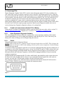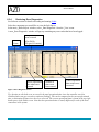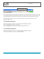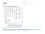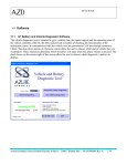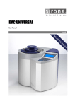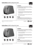
1
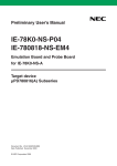
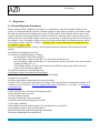
Service Manual 6 Diagnostics 6.1 General Diagnostic Procedures Before starting with any diagnostic procedures, it is important to verify the complaint. With any new system, it is important that the operator is familiar with the normal vehicle operation. An example would be when the operator turns the ignition key to the START position. With a normal vehicle, they would expect to hear the starter engage and they would release the key when the engine starts. As the key start position only activates the high voltage system, the operator may cycle the key on and off several times in an attempt to “start” the engine. Doing so may activate the lock-out which will then prevent the vehicle from going to the HV mode for 3 minutes. A flashing ― Wait‖ on the instrument panel might then cause the operator to report a fault. Once the complaint has been verified, a visual inspection must be preformed. This inspection should include: All fluid levels including the fuel level 12 volt battery condition and state of charge Are the batteries sufficiently charged? Does the battery voltage remain above 12 volts when with the key on? Does the battery voltage remain above 12 volts when the vehicle is on in HV mode, all accessories running including A/C, etc? If the voltage is below 12 volts, check battery for insufficient capacity and vehicle electrical system for an abnormally high draw. All electrical connectors connected and secure Check that the Inertia Switch has not been tripped. Check all ground connections to ensure they are clean and tight Vacuum hoses connected All intake and exhaust components secure and not leaking Check for DTCs. Repair any codes before proceeding. If it is not possible to communicate with the VCU or Battery, refer to section 7.8 DCAN Communication Faults Pinpoint test 3 or section 7.16 No Battery Communications. Verify fuel supply Is there sufficient fuel, and does the fuel pump operate? Has the fuel filter been serviced? Verify the Ignition System Has proper maintenance been preformed? Are all electrical connections properly secured? Verify engine condition Is the compression good with less than a 10% variation between cylinders? Is the ignition system in good operating order? Has the fuel injection system been properly maintained? Has normal maintenance been preformed? Azure Dynamics Series Hybrid Electric Vehicle – 2006/7 Shuttle Bus MAN500666 Rev A 20 Service Manual 6.2 Road Test Often it will be necessary to road test the vehicle to either locate a fault or verify the repair. This is particularly important for intermittent faults that may only appear while driving the vehicle. The following conditions should be completed to ensure all driving conditions are completed. Obey all local traffic regulations including posted speed limits. Start the vehicle and go to the high volts mode. Clear all codes. A route should be selected which requires a minimum left turns across traffic. If monitoring of diagnostic software is required, a second person must drive the vehicle. Do not attempt to view diagnostic screens while the vehicle is in motion. Duplicate the route from driver‘s complaint: i.e. if the complaint is during high speed operation, extend the high speed portions of the road test. If the concern occurs on rough roads, try to duplicate the speed and conditions as reported. Route should include: o Stop and go o Low speed driving below 40 km/h (25 MPH). o High speed at 80 km/h (50 MPH)or higher for a minimum of 15 minutes o Wide open throttle acceleration from a stop to 80 km/h (50 MPH). o If looking for temperature or battery faults, heavy acceleration / heavy regenerative braking is often required: Aim for ― heavy regenerative braking‖ – heavy acceleration up to speed, and then just enough brake to turn on the brake lights (depress brake pedal ½ - 1 inch) and allow the vehicle to decelerate by regening as much as possible. Perform as safely as possible. o Rough roads, low speed over speed bumps/ railway tracks/ potholes, and high speed over washboard roads above 55 km/h(35 mph) o At least three 3 point turns or parking lot maneuvers to test low speed heavy load response. o Ensure engine shutdown at stops o Monitor SOC during road test o Observe all gauges and warning lights o A minimum of 3 key cycles should be preformed ranging from 10 seconds to 3 minutes between cycles. o All electrical accessories should be on to load the 12 volt charging system o Radio should be turned down to listen for noisy pumps or other components. o Recommended testing time is 1 hour or until fault sets Check for codes set during the road test. Azure Dynamics Series Hybrid Electric Vehicle – 2006/7 Shuttle Bus MAN500666 Rev A 21 Service Manual 6.3 Retrieving DTCs Engine Diagnostic Trouble Codes (DTCs) can be retrieved from the engine ECU using a suitable scan tool, such as the Tech-II. If a generic scan tool is used, verify DTC description proper service. When the key is turned from the OFF position to the ON position, the ECU will be powered up and communications will be possible. Once the system is in HV mode (following key START), the VCU will switch the ECU on and off as required. If it is necessary to have the system in the HV mode for diagnostics, it may be required to jump the ECU power relay to maintain communications and to keep the engine running. Removing the EPAS Control Circuit connector will also cause the engine to continue to run as this will be detected as an EPAS fault requiring engine operation. Hybrid system diagnostic trouble codes can be retrieved using Azure Dynamics diagnostic software or by using Siadis. 6.3.1 Unable to Communicate with the VCU or Battery If the software is unable to communicate with the system to retrieve the error codes, refer to section 7.8 DCAN Communication Faults Pinpoint test 3 or section 7.16 No Battery Communications. 6.3.2 Azure Dynamics Diagnostic Software The Azure Diagnostic Software allows the viewing of the various operating conditions of the hybrid system and the battery as well as reading and diagnostic codes that may be set. Also, if necessary, the battery SOC (State of Charge) can be changed using this software. 6.3.3 Siadis General Requirements for Siemens Software NOTE: In this section the VCU (Vehicle Control Unit) may be referred to as a DICO. This is because the Siemens Software will refer to DICO when making selections of the various components. See the Glossary of Terms for more details. All Siemens Software procedures require the use of a Peak CAN dongle that plugs into the parallel port of a computer as well as the USB port (for power), a Peak CAN PCMCIA card or a USB version of the card. Note: if using the dongle, the dongle should only be plugged in when the laptop is powered down (or in hibernation mode) and with some computers, it will need to be plugged and then re-booted so that the computer recognizes it. Standard off the shelf straight thru RS-232 cables with D-Sub 9 ends should be used to connect between the Peak CAN card or dongle and the vehicle. It is recommended that the length of the cable used not exceed 6 feet since the CAN messages could be affected with longer cables. The connector number on the vehicle that allows communication with the Siemens DCAN network is number C100S, a DSUB9 connector located under the instrument cluster. Figure 1 Azure Dynamics Series Hybrid Electric Vehicle – 2006/7 Shuttle Bus MAN500666 Rev A 22 Service Manual 6.3.4 Retrieving Error Diagnostics See Software section for details on loading and running Siadis. Select the component you would like to view the fault log for. In the main ‗Siadis-Expert‘ window, select ‗Error Diagnostic‘ from the ‗View‘ menu. A new ‗Error Diagnostic‘ window will pop up containing any error codes that have been logged. Error Name Component in which error occurred (Gw=DICO, G1=gen, D1=motor) Vehicle Operational Time when error occurred Number of times error has occurred Vehicle operation data at time error occurred Figure 2 Error Diagnostic Screen Tip: the time at which the error occurred is the total operational time since the controller was first initialized (does not get reset due to software flashing). This can be compared to the current operational time, to determine the time since the error occurred. The current operational time is found in the top right hand corner of the Siadis screen. Note that the operational time is usually different for each of the three controllers in the system. Azure Dynamics Series Hybrid Electric Vehicle – 2006/7 Shuttle Bus MAN500666 Rev A 23 Service Manual Current operational time Figure 3 Operational Time The last code listed on the error diagnostic screen is the newest code, the top one is the oldest code. If the error diagnostic buffer is full, the oldest code will be overwritten. However if there are repeat codes, then the oldest identical code will be removed, and the count column will be incremented for the new entry. The DICO controller will store the error diagnostic data for the generator and motor in its error diagnostic buffer as well. 6.4 Saving Error Diagnostics Follow steps outlined in section 6.3.3 to bring up the Error Diagnostics window Select ‗Save Diagnostic‘ from the ‗File‘ menu. Type in an appropriate file name and save with the default extension *.err 6.5 Clearing Error Diagnostics Follow steps outlined in section 6.3.3 to bring up the Error Diagnostics window Under the ‗Error-Buffer‘ menu, select ‗Delete ErrorBuffer‘. Azure Dynamics Series Hybrid Electric Vehicle – 2006/7 Shuttle Bus MAN500666 Rev A 24