1
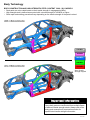
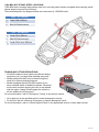
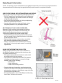
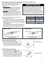
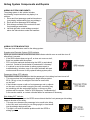
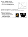
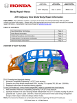
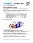
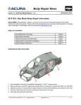
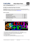
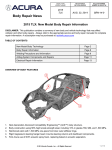
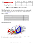
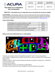
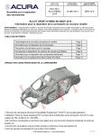
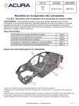
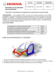
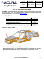
MODEL/YEAR
MODÈLE /ANNÉE
DATE OF ISSUE
DATE EN VIGUEUR
BULLETIN NUMBER
NUMÉRO DU BULLETIN
2009 TL
APRIL 25, 2014
BRN-14-2
Body Repair News
2009 TL: Body Repair Information
DISCLAIMER: This publication contains a summary of body and vehicle technology that may affect collision
and other body repairs. Always refer to the appropriate service and body repair manuals for complete repair
information. A subscription may be purchased at: techinfo.acura.com
TABLE OF CONTENTS
Body Technology
Page 2
Aluminum Parts and Repairability
Page 4
Body Repair Information
Page 5
Welding Precautions and Information
Page 6
Airbag System Components and Repairs
Page 8
Electrical Repair Information
Page 9
OVERVIEW OF BODY FEATURES
1. Advanced Compatibility Engineering™ (ACE™) body structure.
2. Body construction using 48%+ high tensile strength steel, including 5%+ in grades 980, and 1,500 MPa.
3. Aluminum body components used in key areas for weight reduction and improved fuel efficiency.
© 2014 Honda Canada., Inc. – All Rights Reserved
1 of 10
Body Technology
BODY CONSTRUCTION AND HIGH STRENGTH STEEL CONTENT 2009 - 2011 MODELS
• Steel parts are color-coded based on their tensile strength in megapascals (MPa).
• High strength steel is defined as any steel with a tensile strength of 340 MPa or higher.
• Steel repair and welding procedures vary depending on the tensile strength of the parts involved.
270 MPa
440 MPa
590 MPa
980 MPa
1,500 MPa
Steel Tensile
Strength Legend
Important Information
These illustrations are for general reference only.
Some body parts are constructed from multiple layers
of different tensile strength steels. Always refer to the
body repair manual body construction section for
specific steel tensile strength information.
2 of 10
1,500 MPa (HOT STAMP) STEEL LOCATIONS
1,500 MPa steel is stronger than ordinary steel, so it can help protect vehicle occupants while reducing overall
vehicle weight to improve fuel efficiency.
The numbered parts in the diagrams below are constructed of 1,500 MPa steel:
2009 – 2011 Models
1
Center Pillar Stiffener
2
Side Sill Reinforcement
2012 – 2014 Models
1
Center Pillar Stiffener
2
Side Sill Reinforcement
3
Center Pillar Inner Stiffener
TOWING AND LIFTING PRECAUTIONS
• SH-AWD models must be towed using flat bed towing
equipment only, or transmission damage may result.
• Models without SH-AWD may be towed using front
wheel lift or flat bed towing equipment.
• Models equipped with the SH-AWD system do not
have a manual switch to disable the system. Whenever
service work requires spinning the front or rear wheels
with the engine, always lift and support the vehicle so
all four wheels are off the ground.
For more information, refer to “Emergency Towing” in the owner’s manual.
• Lift or jack only at the specified points to avoid damaging the vehicle.
• Do not lift or tow this vehicle by its bumpers, or serious damage will result.
For more information, refer to “Lift and Support Points” in the appropriate service or body repair manual.
3 of 10
Aluminum Parts & Repairability
The hood panel and both bumper beams are constructed of aluminum alloy.
Repairability Issues:
• Do not repair the bumper beams if damaged.
• The aluminum hood may be repaired by body
shops that have a dedicated aluminum repair
facility and separate tools.
• To prevent galvanic corrosion, some fasteners for
aluminum parts are considered one-time use and
must be replaced if removed. Refer to the service or
body repair manual for more information.
STEERING HANGER BEAM
The steering hanger beam provides mounting for the steering column and dashboard components.
• The beam uses aluminum construction for weight savings.
• Do not repair the steering hanger beam if it is damaged.
• Special threaded collar bolts are used on the
passenger side of the beam to compensate for any
variation in body dimensions.
• A specific installation and bolt tightening procedure
is required.
• Refer to “Dashboard/Steering Hanger Beam
Removal and Installation” in the service manual for
complete information.
4 of 10
Body Repair Information
NOTE: The following content is intended only to highlight new/special concerns. No body repairs should be
attempted without first referencing the appropriate body repair manual for complete information.
USE OF HEAT DURING BODY STRAIGHTENING AND REPAIR
When you are doing body straightening and repair procedures:
• DO NOT apply heat to any body part during straightening.
This may compromise the internal structure and strength
of high-strength steel parts.
• Any part that has heat applied to it during straightening
MUST be replaced with new parts.
• Ignoring these instructions may significantly reduce
occupant protection in any subsequent collision.
SECTIONING (CUT AND JOINT) GUIDELINES
Because of body structure improvements for collision
safety and rigidity, the materials, steel thickness, and
internal reinforcements have become very specific.
Follow these guidelines to avoid an unsafe repair:
• Avoid sectioning (cut and joint) except for outer panels
and floor panels unless a specific procedure is provided
in the body repair manual.
• Replace body structural components as assemblies
that match the replacement parts configuration.
• Refer to “Front Side Frame and Rear Frame Cutting
and Splicing” in the body repair manual for sectioning
opportunities.
BLIND SPOT INFORMATION (BSI) SYSTEM
Models equipped with this system can be identified by
this BSI Alert Indicator, located on both front doors near
the outside rearview mirror.
• The system uses a radar unit located on each side of
the vehicle behind the rear bumper.
• The system may malfunction and set DTCs because
of damage, improper repairs, or excessive foreign
material on any of the following:
• Rear bumper
• Outer side panels
• Radar unit mounting locations
•
•
Several checks and inspections must be done during
repairs to the radar unit mounting area. If the mounting
area check is not done, an Acura dealer may not be able
to properly aim the radar units.
For more information, refer to “BSI Radar Unit Mounting
Area Check” in the service manual.
5 of 10
Welding Precautions and Information
REPAIRING 1,500 MPa STEEL PARTS
Observe these precautions when repairing 1,500 MPa steel parts:
• NEVER attempt to straighten damaged 1,500 MPa
steel parts because they may crack.
• 1,500 MPa steel parts MUST be replaced at factory
seams using squeeze-type resistance spot welding
(STRSW).
• MIG brazed joints should be used ONLY in locations
not accessible by a spot welder.
• To assure adequate weld tensile strength, always
set the spot welder to the specifications provided in
the body repair manual.
Important Information
Parts made of Ultra High Strength Steel
(UHSS/1,500MPa/ USIBOR) must be installed as a
complete part. No sectioning allowed. Ultra High
Strength Steel requires special welding equipment,
procedures, and settings. See the welding section of
the appropriate body repair manual. Failure to use the
proper equipment or follow the proper procedures can
result in an unsafe repair.
•
•
•
NEVER perform MAG welding on 1,500 MPa steel.
The heat generated during welding will significantly
reduce the strength and structural integrity of
1,500 MPa steel parts.
This photo shows tensile strength test results of
welded 1,500 MPa steel. The 1,500 MPa steel fractured
first, because the welding heat reduced its strength to
far below 590 MPa.
For more information, refer to “Hot Stamp (1,500 MPa)
Parts Welding Specifications” in the body repair manual.
MIG BRAZING GUIDELINES FOR 1,500 MPa STEEL PARTS
Refer to the body repair manual for complete information:
• MIG brazed joint locations are specified in the
body repair manual.
• A single- or double- hole MIG braze may be
specified in the body repair manual depending on
the tensile strength of the parts being joined.
• The size and number of holes are critical to
achieving adequate joint strength.
• A pulsed MIG welder MUST be used. Refer to the
equipment manufacturer’s instructions for welder
voltage and current setup.
• The photos at right show the difference in results
between pulsed and non-pulsed MIG brazing.
6 of 10
MAG WELDING SPECIFICATIONS FOR 590-980 MPa HIGH-STRENGTH STEEL PARTS
NOTE: In this publication and the body repair manuals,
gas metal arc welding (GMAW) is referred to by its
Important Information
subtypes depending on the welding/brazing
requirements:
Parts made of High Strength Steel (590-980 MPa)
• MIG welding/brazing = Metal inert gas welding or
must be installed as a complete part. No sectioning is
brazing where 100% argon (Ar) shielding gas is
allowed unless a procedure is provided in the body
used. Argon is inert and does not react with the
repair manual. This high-strength steel requires
molten weld pool or brazing operation.
special welding equipment, procedures and settings.
• MAG welding = Metal active gas welding where
See the welding section of the appropriate body repair
the shielding gas being used contains a mixture of
manual. Failure to use the proper equipment or follow
80% argon (Ar) and 20% carbon dioxide (CO2).
the proper procedures can result in an unsafe repair.
It is considered active because the CO2 undergoes
a limited reaction with the molten weld pool.
The body repair manual specifies the weld types and
locations for each body panel:
• The welding wire used must have a tensile strength equal
to, or greater than, the lowest tensile strength of the parts
being welded. This conversion chart shows the relationship
of steel tensile strength (MPa) to the minimum welding wire
tensile strength (ksi).
• Typical ER70S-6 MIG wire has a minimum tensile strength
of 70 ksi (483 MPa). It can be used when welding up to
440 MPa steel parts. Refer to the diagrams shown below:
Steel Tensile (MPa)
Wire Tensile (ksi)
590
≥86
780
≥113
980
≥142
(1,000 psi = 1 ksi)
MAG PLUG WELDING GUIDELINES
• MAG plug welding may be done when joining body
components to 590-980 MPa steel parts.
• Follow the recommendations described in the body
repair manual section “MAG welding specifications
for high-strength steel parts 590 MPa and higher.”
MAG BUTT WELDING GUIDELINES
• MAG butt welding may be done only on steel parts
with a tensile strength of 590 MPa and lower.
• Welding speed is critical to achieve the correct weld
strength and minimize the heat affected zone (HAZ).
• Follow the recommendations described in the body
repair manual section “MAG welding specifications
for high-strength steel parts 590 MPa and higher.”
7 of 10
Airbag System Components and Repairs
AIRBAG SYSTEM COMPONENTS
The airbag system in this vehicle includes
the following components that may deploy in a
collision:
1. Driver and front passenger seat belt tensioners
(may deploy independently from any airbags).
2. Driver and front passenger SRS airbags.
3. Side airbags mounted in the outer driver and
front passenger seat-backs.
4. Left and right side curtain airbags mounted
above the side windows under the headliner.
AIRBAG SYSTEM INDICATORS
There are three indicators used for the airbag system:
Supplemental Restraint System (SRS) Indicator
When you turn the vehicle to the ON mode, this indicator should come on and then turn off
after about 6 seconds.
• If the SRS indicator does not go off, or does not come on at all,
there is a problem with the system.
• DTCs must be read and cleared using the HDS (or equivalent)
scan tool. Contact a Honda dealer for assistance if necessary.
• If a vehicle is sent to the dealer for airbag system repair or
troubleshooting, include a copy of the repair estimate with part
numbers and the source for any replaced airbag system parts.
Passenger Airbag OFF Indicator
The indicator comes on to alert you that the passenger’s front airbag has been turned off.
• This occurs when the front passenger’s weight sensors detect
65 lb. (29 kg) or less, the weight of an infant or small child,
on the seat.
• If the indicator comes on with no front passenger and no objects
on the seat, or with an adult occupying the seat, something may
be interfering with the seat weight sensors, or there may be a
problem with the system. Refer to “SRS Symptom Troubleshooting”
in the service manual, or contact a Honda dealer for assistance if necessary.
Side Airbag OFF Indicator
This indicator comes on when the OPDS sensor detects that the front passenger side airbag
needs to be shut off for safety:
• This may occur because the passenger is too small to be sitting
in the front seat, is slouching or not sitting upright, or has leaned
into the airbag's deployment path.
• This light is not used to indicate problems with the OPDS or
airbag system.
8 of 10
AIRBAG SYSTEM ELECTRICAL REPAIRS
Except when doing electrical inspections that require battery power, always turn the vehicle to the OFF (LOCK)
mode, disconnect the negative battery cable, then wait at least 3 minutes before starting work.
• For easier identification, electrical connectors that contain only
airbag system wiring are yellow in color.
• Many harnesses that contain primarily airbag wiring are also
wrapped in yellow tape.
• Airbag system wiring that runs in a common harness, such as a
floor harness, is generally not marked.
• NEVER attempt to modify, splice, or repair airbag system wiring.
If airbag system wiring is damaged, replace the wiring harness(es).
NOTE: Refer to the service manual for complete restraint system
operation, diagnostic, and repair information.
Electrical Repair Information
TIRE PRESSURE MONITORING SYSTEM (TPMS)
This vehicle is equipped with an initiator-type TPMS.
• The low tire pressure/TPMS indicator comes on if the air pressure
is too low in one or more tires. TPMS messages will also appear
on the multi-information display in the gauge control module.
• The TPMS indicator will stay on and the system will set DTCs if
all four tire pressure sensor IDs are not memorized by the TPMS
control unit after you replace a wheel and/or tire pressure sensor.
• Refer to “Memorizing a Tire Pressure Sensor ID” in the service
manual for complete information.
• The HDS (or equivalent) scan tool may be required to perform this
memorization. Contact an Acura dealer for assistance, if necessary.
9 of 10
ELECTRICAL GROUND WIRE PROTECTION
• Painting over electrical ground locations may cause
electrical systems, such as Vehicle Stability Assist
(VSA), to malfunction and set DTCs that may be
difficult to diagnose.
• Protect the ground wire and the ground wire mounting
hole threads with a bolt or plug when priming or painting.
SYSTEMS THAT MAY REQUIRE DEALER ASSISTANCE WITH AIMING
Some models may be equipped with the following system that requires aiming after collision repairs.
Special tools are required to complete the aiming procedures. Contact an Acura dealer for assistance.
Blind Spot Information (BSI) System:
The BSI radar unit must be aimed in these instances:
• After replacing or removal and installation of
one or both BSI radar units.
• After replacing/repairing the body rear outer side
panel(s) where the radar units mount.
• Stored DTCs B18B8 or B18B9 - left or right side
BSI radar unit azimuth off alignment.
If a problem occurs in the BSI system, the amber BSI
indicator will illuminate and this MID message will also appear.
10 of 10