1
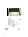
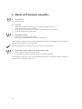
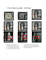
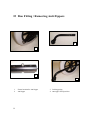
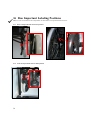
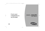
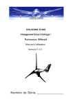
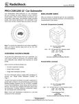
Invacare ®Duo Range
Service/Maintenance Manual
1
Introduction
This manual provides basic details to enable the Invacare® DUO RANGE™ Wheelchair to be
maintained. It is not intended to be a comprehensive maintenance guide/policy, but is intended for
use by authorized personnel to enable the chair to be adequately maintained.
The Wheelchair is manufactured by:
INVACARE Ltd
South Road
Bridgend Industrial Estate
Bridgend
Mid-Glamorgan
CF31 3PY
Invacare provides the following documentation in regards to the Duo Range wheelchair, User Manual, Spare parts list
and Prescription forms.
All of these documents are provided for on the Invacare web site or by contacting Customer Services
Sales/Technical Services Telephone:
Sales Fax:
Technical Services Fax:
Email:
Web:
01656 647327
01656 649016
01656 753299
[email protected]
http://www.invacare.co.uk
For TECHNICAL ADVICE, repairs, servicing, contact Technical Services.
For SPARE PARTS orders contact Customer Services.
Quote the following details at all times:
Part Number (see Spare Parts Catalogue)
Description
Quantity required
Serial Number
Chair Type
This manual contains copyrighted information. This manual may not be reproduced or reprinted either partly or completely
without previous written consent from Invacare® or its statutory representatives. We reserve the right to make any necessary
alterations on the grounds of technical improvements.
2
Policy
INVACARE Ltd Policy is as follows:
Repairs to any component other than those detailed in this manual are not covered. Repairs to any tube metal work are
not generally permitted without express permission of INVACARE Ltd. All fasteners i.e. bolts, Nyloc nuts, and any
fastener showing damage must be renewed.
Under no circumstances attempt to repair a crash damaged chair. Contact Technical Services for further Information.
Alterations to the wheelchair which occur as a result of incorrectly or improperly executed maintenance or overhaul
work lead to the exclusion of all liability on the side of INVACARE.
We reserve the right to make any alterations on the grounds of technical improvements.
Information about operation or about general maintenance and care work should be taken from the wheelchair User
Manual.
Failure to comply with the above absolves INVACARE Ltd of liability.
Note: Certain components will require removal to carry out maintenance. These components should be refitted.
Product End of Life
Even though your Powerchair has been designed to provide a long and trouble free life it is inevitable that
wear, tear and usage will eventually render the product unusable.
INVACARE recommends that the average usable life of this product is five years, providing the product has
been correctly maintained according to the manufacturer’s recommendations.
When the time comes to replace your wheelchair please remember to dispose of the product responsibly
and recycle any recyclable parts as mentioned in this user guide.
Notes on Transport
If the wheelchair has to be shipped back to the manufacturer for major repairs, you should always use the original
packaging for transport.
You should also include as accurate a fault description as possible.
Information Symbols
NOTE: This symbol identifies general information which indicates special points or simplifications in dismantling
/ reassembly.
CAUTION: It is imperative that you observe any safety instructions identified with this symbol.
TOOLS/SERVICE: This symbol identifies service work or tools required.
EXPLOSION HAZARD!
This symbol warns you of an explosion hazard, which can be caused by excessive tyre pressure in a pneumatic tyre!
Always follow the instructions to avoid injury to the user or damage to the product!
TRANSPORTATION:
This symbol identifies important information relevant to transporting your wheelchair in a motor vehicle.
3
Contents
Section
Page
1
Layout of Duo Range
5-6
2
Safety and Assembly Instructions
7
3
Tools Required
8
4
Technical Detail
9
5
Intended Use
10
6
Backrest Assembly
11 – 12
7
Backrest Extension Assembly
13 – 14
8
Armrest Assembly
15 – 16
9
Rear Wheel Assembly – Transit
17 – 18
10
Rear Wheel Assembly – Self Propel
19 – 21
11
Brake Assembly
22 – 23
12
Castor Wheel Assembly
24 – 25
13
Swing Away Footrest Assembly
26 – 27
14
Manual Elevating Swing Away Footrest Assembly
28 – 29
15
Seat Canvas Assembly
30 - 31
16
Duo Fitting/Removing Anti tipper
32 – 33
17
Duo Important Labeling Positions
34 - 35
4
1 Layout of Duo Range
Duo Self Propelling Wheelchair
1
2
8
7
4
6
1
2
3
4
5
Backrest assembly
Armrest assembly
Self propelling rear wheels
Manual Brake assembly
5
5
6
7
8
Castor assembly
Footplate assembly
Hanger assembly
Seat canvas
3
Duo Transit Wheelchair
1
2
8
3
7
4
6
1
2
3
4
Backrest canvas
Armrest assembly
Transit Rear wheels
Brake assembly
6
5
5
6
7
8
Castor assembly
Footplate assembly
Hanger assembly
Seat canvas
2 Safety and assembly instructions
These safety instructions are intended to prevent accidents at work your suitable workshop environment and it is
imperative that they are observed.
2.1 Before any inspection or repair work
Read and observe this maintenance manual and the associated user manual.
Caution:
Prop up the wheelchair with appropriate supports before starting the disassembly or assembly.
Never use standard nuts instead of self-locking nuts. .
When using loctite use goggles and gloves
2.2 Before operation / after completion of work:
Caution:
Check all fixings for tight fit (Ref torque settings where applicable).
All nyloc nuts should be replaced with new after removal
Check brake assembly fully locks and that chair is unable to move.
Check hand grips are secured cannot twist or pull off.
Check that folding back plunger locks securely into lower back post when push handle is in the upright position
Check seat and back upholstery are in a good condition
Check footrest is correctly fitted
Check hanger assembly is in working order and correctly fitted.
If anti tippers are fitted they are firmly locked in place.
Lap belt is securely fitted and in good condition
Check brazed parts are in good condition
Only operate wheelchair with correct tyre pressure. (When applicable)
Check that Transportation tie down labels are visibly in good condition (Replace if necessary).
As a last check, always carry out a trial run.
2.3 Disposal/Recycling Components
•
•
•
•
•
•
7
The equipment wrapping is potentially recyclable.
The metal parts are used for scrap metal recycling.
The plastic parts are used for plastic recycling.
Electric components and printed circuit boards are disposed of as electronic scrap.
Disposal must be carried out in accordance with the respective national legal provisions.
Ask your city or district council for details of the local waste management companies.
3 Tools Required
The following list gives the basic tools required to perform the maintenance procedures as
illustrated in this manual. None of which are supplied by Invacare.
Open End Spanner (10mm)
Open End Spanner (11mm)
Open End Spanner (15/16”)
Open Ended Spanner (17mm)
Open Ended Spanner (19mm)
Socket / Wrench (19mm)
Open Ended Spanner (22mm)
Open Ended Spanner (24mm)
Open Ended Spanner (26mm)
Cross Point Screwdriver
Flat Bladed Screwdriver
Nylon Mallet
Torque Wrench
Hexagon Wrench - (4mm)
Hexagon Wrench - (5mm)
Knife
Pressure Gauge
Pump
Valve Remover
Pair Pliers
Safety Goggles
Gloves
Note: Ensure cleaning/Disinfecting of product is followed before carrying out any maintenance, pay
attention to the following points:
Only use a damp cloth and gentle detergent.
Do not use any abrasive or scouring agents.
Do not use any high-pressure cleaning devices.
8
4 Technical Detail
4
The following data applies to the Duo range of wheelchairs.
4.1
Available Standard seat sizes:
15 inches by 16 inches, 16 inches by 16 inches, 17 inches by 17 inches and 18 inches by 17 inches.
4.2
Available Heavy Duty seat sizes:
20 inches by 17 inches, 20 inches by 18 inches, 22inches by 17 inches, 22 inches by 18 inches, 24 inches by 17
inches and 24 inches by 18 inches.
4.3
Seat to ground height:
19 inch.
4.4
Wheel types available:
12 ½ inch transit with pneumatic or solid tyre. Fixed to frame.
22 inch Self-Propelling pneumatic or solid, Quick Release or Bolt On.
4.5
Maximum standard & Heavy Duty user weight:`
Standard 19.5 stones (125kgs) and Heavy Duty 25 stones (160kgs)
4.6
Backrest type:
Folding backrest or Fixed Vertical
4.7
Chair Colour:
Powder coated black.
4.8
Approximate weight of chair Standard and Heavy Duty size
Standard size Transit chair 19.5Kg
Standard size Self Propel chair 22.5Kg
Heavy Duty size Transit chair 22Kg
Heavy Duty size Self Propel 25Kg
Note: The chair is available in various defined optional types. Refer to Invacare Ltd Prescription forms or for further
assistance contact Invacare Customer Services
9
5 Intended Use
Environmental Use
The Standard Duo Range is an Indoor and Outdoor configurable wheelchair offered with various options compliant with
EN12184:1999 section 5 class B
The Heavy Duty Duo Range is an Indoor and Outdoor wheelchair with various options compliant with EN12184:1999 section 5
class B.
Type of User
The Standard Duo Range has been designed to provide mobility and comfort for persons with impaired mobility.
The Heavy Duty Duo Range has been designed to provide mobility and comfort for persons with impaired mobility.
Manner of Use
The Standard Duo Range has been designed to be used either/or by a seated user/carer/attendant in both indoor and outdoor
environments
The Heavy Duty Duo Range has been designed to be used either/or by a seated user/carer/attendant in both indoor and outdoor
environments
Standard Use
The Standard Duo Range has, in its standard format, been designed to accommodate users who weigh up to a maximum of
125kg, have all limbs intact and have sufficient upper body strength to maintain a safe position within the wheelchair without
the addition of supporting aids.
The Heavy Duty Duo Range has, in its standard format, been designed to accommodate users who weigh up to a maximum of
160kg, have all limbs intact and have sufficient upper body strength to maintain a safe position within the wheelchair without
the addition of supporting aids.
Specialist Use
Adaptations from the standard wheelchair format are available to accommodate users who do not meet the above criteria but
these will only be considered after a suitable assessment of the risks has been carried out by a qualified person. For example a
user with either a full or a partial amputation or other condition which affects the natural Centre of Gravity will need to have a
stability evaluation to minimize the risk of inadvertent tipping.
Standard Recommendations
The wheelchair should only be used in accordance with the safety advice given within this user guide. Failure to follow the
recommended advice within this user guide could lead to personal injury.
Specific Recommendations
No claims are made that the product will medically improve the circumstances or condition of the user.
10
5 Backrest Assembly
1
2
3
UNLOCK
4
5
8
LOCKED
7 6
9
10
View of rear Backrest Assembly
11
12
13
1
2
3
4
5
6
7
11
Backrest canvas
Hand grips
Push handles
Plunger knob ¼” x 28 UNF
M6 Pivot bolt
Plunger Countersunk
M6 ID washer
8
9
10
11
12
13
M6 Nyloc nut
Counter sunk screw
Cup washer
Push Bar
Hand Knob
Lap Belt
5 Backrest Assembly
5.1
Tools Required
Open ended Spanner (10mm) x 2.
Cross point screw driver
5.2
Inspection
1.
2.
3.
4.
5.
6.
7.
Check that the backrest canvas is not unevenly stretched, worn or torn.
Check that all stitches are in good condition.
Check that all screws and washers are secured, in good condition and are not burred.
Check pivot bolt is secured.
Check plunger assembly is secure and functional.
Check hand grip cannot twist or pull off.
Check that lap belt is secure and locking mechanism is functional.
Note: Testing has confirmed hair spray is sufficient to secure hand grip to push handle. (Recommend Tescos
Value hairspray).
5.3
Disassembly/Assembly
1.
2.
3.
4.
5.
6.
7.
Lock brakes to prevent movement of chair
Unscrew push bar hand knobs to remove push bar (only applicable to Heavy Duty Models)
Unscrew and remove the top four countersunk screws and cup washers.
Unscrew and remove the bottom two countersunk screws, cup washers and lap belt.
Unscrew and remove the two button head M6 pivot bolts, nyloc nuts and washers.
Hold the push handle, and slide the lower half of the backrest canvas off.
Hold the backrest canvas and slide the push handle out.
To re-assemble reverse the above steps, ensuring that the fixation holes in the upholstery and tubes are aligned.
Making sure that all fixation screws are hand tight.
Caution: When removing/replacing fasteners from backrest assembly ensure you replace the nyloc nuts. When
replacing plunger knob ensure you apply loctite solution 243. When using hairspray please following safety
guidelines on hairspray can.
12
6 Backrest Extension Assembly
9
10
2
1
3
4
5
6
7
8
1
2
3
4
5
13
Backrest canvas
Hand Grips
Push Handles
Plunger Knob
Pivot Bolt
6
7
8
9
10
Plunger
Counter sunk screw
Cup washer
Backrest Extension
Hand Knob
6 Backrest Extension Assembly
6.1
Tools Required
Cross point screw driver
6.2
Inspection
1.
2.
3.
4.
Check that the backrest extension canvas is not unevenly stretched, worn or torn.
Check that all stitches are in good condition.
Check that all screws and washers are secured, in good condition and are not burred.
Check that hand knobs are securely fitted.
6.3
Disassembly/Assembly
1.
2.
Lock brakes to prevent movement of chair.
Remove the four Hand knobs from the backrest extension tubes.
To re-assemble reverse the above steps, ensuring that the fixation holes in the upholstery and tubes are aligned.
Making sure that all fixation screws are hand tight.
Note: Assembling backrest extension for the first time. Follow instructions below.
6.4
Disassembly/Assembly of Backrest Extension for the first time
1.
2.
Remove counter sunk screws from push handles.
Fit four hand knobs through extension tubes and secure to the push handles.
To re-assemble reverse the above steps, ensuring that the fixation holes in the upholstery and tubes are aligned.
Take care not to over tighten fixation screws.
14
7 Armrest Assembly
VIEW WHEN LOCKED
VIEW WHEN UNLOCKED
1
2
3
4
5
1
2
3
15
Armrest Pad
Sealing Plug
Armrest Frame
4 Counter Sunk Screw
5 Skirt Guard
7 Armrest Assembly
7.1
Tools Required
Cross point screw driver
7.2
Inspection
1.
2.
3.
4.
Check that frame and panel are in good condition.
Check that armrest pad is in good condition and securely fastened.
Check that armrest locking mechanism is functional.
Check that sealing plug is secure and in good condition
Note: For ease of maintenance the armrest assembly can be purchased as a complete assembly.
7.3
Disassembly/Assembly
1.
2.
3.
4.
Lock brakes to prevent movement of chair.
Rotate locking mechanism in forward position and lift out armrest assembly from side frame.
Remove skirt guard by holding the armrest frame firmly whilst push the skirt guard forward.
Unscrew and remove both counter sunk screws.
Remove armrest pad from armrest frame.
To re-assemble reverse the above steps, ensuring that the fixation holes in the tube are aligned.
16
8 Rear Wheel Assembly - Transit
1
2
3
1
2
17
Solid Transit Rear Wheel
Pneumatic Transit Rear Wheel
4
3 Star Loc Washer
4 7/16 UNF Lock Nut
8 Rear Wheel Assembly - Transit
8.1
Tools Required
Open Ended Spanner (19mm)
Socket / Wrench (19mm)
Nylon Mallet
Torque Wrench
8.2
Inspection
1.
2.
Check wheel is not buckled or physically damaged. Replace if required.
Check tyre for wear (and correct inflation when applicable), both wheels should allow the same degree of
wear (see side of tyre for pressure rating).
Check that lock nut is secured to the axle bolt.
Check brake alignment is horizontal to tyre.
Check brake functionality.
3.
4.
5.
Note: For ease of maintenance the transit rear wheel assembly can be purchased as a complete assembly, or by
purchasing tyre and inner tube (if pneumatic).
Caution: Take care while supporting the wheel chair in order to remove the wheel.
8.3
Disassembly/Assembly
1.
2.
3.
Raise and support the chair so that the damaged wheel is free of the ground.
Remove lock nut and star loc washer using suitable size spanner.
Remove the wheel free from its location on the side frame.
To re-assemble reverse the above steps, ensuring that the wheel is securely fitted.
8.4
Disassembly/Assembly of Pneumatic Tyre
1.
2.
3.
4.
5.
Refer to 8.3 for removal of wheel assembly.
Remove tyre using suitable tyre levers.
Remove inner tube (when applicable).
Replace inner tube or tyre as appropriate.
Inflate tyre to correct inflation
To re-assemble reverse the above steps, ensuring that the wheel is securely fitted.
Explosion Hazard: Never exceed the pressure on the side walls of the tyre, otherwise, the tyre may explode and
cause injuries!
Caution: Apply loctite solution 243 to the thread of the wheel shaft and ensure that the transit wheel locknut is
tightened to a torque setting of 30 – 40Nm.
18
9 Rear Wheel Assembly – Self Propel
3
1
2
6
4
5
8
7
1
2
3
4
5
Solid Self Propel Rear Wheel
Pneumatic Self Propel Rear Wheel
24” Self Propel Rear Wheel Position
22” Self Propel Rear Wheel Position
20” Self Propel Rear Wheel Position
19
9
6
7
8
9
Set Forward Position. Fixed Wheel Only
Standard Position. Fixed and Quick Release
Set Back Position. Fixed and Quick Release
Handrim Spacer Fitting
9 Rear Wheel Assembly – Self Propel
9.1
Tools Required
4mm Hexagon wrench
10mm Open ended spanner
11mm Open ended spanner
19mm Socket/Wrench
22mm Open ended spanner
26mm Open ended spanner
Torque Wrench
9.2
Inspection
1.
2.
Check wheel is not buckled or physically damaged. Replace if required.
Check by hand that each quick release wheel locates correctly in both quick release axle bushes. Ensuring
that the ball bearings protrude fully to secure a locked position.
Check that there is no significant sideward movement.
Check that fixed axle lock nut is fully secured.
Check that handrim is in good condition and secure.
Check tyre for wear (and correct inflation when applicable), both wheels should allow the same degree of
wear (see side of tyre for pressure rating).
Check that spokes for tension and general condition.
Check brake alignment is horizontal to tyre.
Check brake functionality.
3.
4.
5.
6.
7.
8.
9.
Note: For ease of maintenance the self propel rear wheel assembly can be purchased as a complete assembly.
Caution: Take care while supporting the wheel chair in order to remove the wheel. Handrims are constantly in
contact with your hands. Make sure that they are not damaged.
Explosion Hazard: Never exceed the pressure on the side walls of the tyre, otherwise, the tyre may explode and
cause injuries!
9.3
Disassembly/Assembly of Quick Release rear wheel
1.
2.
3.
4.
Raise and support the chair so that the damaged wheel is free of the ground.
Push in and hold the black plastic quick release button located at the centre of the hub.
Pull the wheel assembly out of the wheel mounting bush.
Remove the axle from hub.
To re-assemble reverse the above steps, ensuring that the wheel is securely fitted.
9.4
Disassembly/Assembly of Fixed rear wheel
1.
2.
3.
Raise and support the chair so that the damaged wheel is free of the ground.
Remove lock nut and star loc washer using suitable size spanner.
Remove the wheel free from its location on the side frame.
To re-assemble reverse the above steps, ensuring that the wheel is securely fitted.
Caution: Apply loctite solution 243 to the thread of the wheel bolt and ensure that the self propel wheel locknut is
tightened to a torque setting of 30 – 40Nm.
20
9.5
Adjusting a Quick Release axle
1.
Using a suitable socket on the nut and a suitable spanner on the axle end, adjust to give a secured fit into the
axle bushes.
Ensure that each quick release wheel locates correctly in both quick release axle bushes. Ensuring that the
ball bearings protrude fully to secure a locked position.
2.
Note: This is confirmed when the black plastic button on axle is fully protruded.
9.6
Disassembly/Assembly of Handrim
1.
2.
3.
4.
Raise and support the chair so that the damaged wheel is free of the ground.
Place the wheel assembly on a suitable surface, or lock to prevent it rotating.
Unscrew and remove the six screws and spacer fittings securing the hand rim to the wheel assembly.
Recover the six spacers.
To re-assemble reverse the above steps, ensuring that the wheel is securely fitted.
9.7
Location of Self Propel Rear Wheel Assembly
1.
2.
3.
4.
5.
6.
Diagram 3 shows the correct setting position for the mounting block to locate a 24” rear wheel assembly.
Diagram 4 shows the correct setting position for the mounting block to locate a 22” rear wheel assembly.
Diagram 5 shows the correct setting position for the mounting block to locate a 20” rear wheel assembly.
Diagram 6 shows the correct Set forward position for fixed wheels only.
Diagram 7 shows the correct Standard position for fixed/QR wheels.
Diagram 8 Shows the correct Set back position for fixed/QR wheels.
Caution: When removing/replacing fasteners from Wheel mounting block ensure you replace the nyloc nuts. We
advice a torque setting of 10Nm. When removing/replacing a quick release wheel mounting bush ensure you
replace hexagon nut using thread loc solution 243. We advice a torque setting of 65 – 75Nm. Repositioning the
rear wheel will affect the stability of the wheelchair.
21
10 Brake Assembly
1
2
1
Brake Assembly For Self Propel
22
2 Brake Assembly For Transit
10 Brake Assembly
10.1
Tools Required
5mm Hexagon wrench
10.2
Inspection
1.
2.
3.
Check that brake assembly fully locks and the chair is unable to move.
Check that brake action is positive and is not stiff.
Check that the brake shoe is horizontal to wheel assembly.
Note: For ease of maintenance the brake assembly can be purchased as a complete assembly. Note the setting
position of the brake assembly.
10.3
1.
2.
3.
Disassembly/Assembly
Ensure that brake assembly is in the unlocked position.
Loosen two socket head screws.
Remove the brake assembly from its location.
To re-assemble reverse the above steps, ensuring that the wheel is securely fitted.
Note: Brake shoe should be positioned 2 – 5mm from tyre.
Caution: Keep fingers away from movable parts to prevent injuries.
23
11 Castor Wheel Assembly
1
2
3
4
1
2
Castor Assembly 7½” x 1¼” Solid
Castor Assembly 7½” x 1¾” Solid
24
3 Castor Assembly 5” x 1” Solid
4 Castor Assembly 5” x 1¾” Solid
11 Castor Wheel Assembly
11.1
Tools Required
24mm Open ended spanner
Torque Wrench
11.2
Inspection
1.
2.
3.
4.
5.
6.
7.
Check that castor fork is in good condition and secured to frame
Check that the tyre is not cracked or excessively worn.
Check that the tyre is firmly fitted and concentric within the rim.
Check that castor wheel rotates freely when lifted clear of the ground and spun.
Check all four wheels sit correctly to ground and function correctly.
Check that wheel spokes are undamaged and in good condition.
Check that there is no damage on thread of mounting stud.
Note: For ease of maintenance the castor wheel assembly can be purchased as a complete assembly.
11.3
1.
2.
3.
4.
Disassembly/Assembly
Raise and support the front of the chair.
Unscrew the castor assembly from the wheelchair frame using a suitable sized spanner on the nut above the
castor fork until the assembly releases from its location
Remove the castor wheel assembly.
Check that the thread form inside the wheelchair's side frame is clean and undamaged.
To re-assemble reverse the above steps, ensuring that the wheel is securely fitted.
Caution: Apply Loctite 243 and ensure that the thread of the castor fork assembly mounting stud is tightened to a
torque of 60 - 80N.m
25
12 Swing Away Footrest Assembly
1
2
3
4
5
1
2
3
26
6
Location Holes
Hanger Assembly
Locking Latch Mechanism
4 Adjustment Bolt
5 Footplate Assembly
6 Heel Loop
12 Swing Away Footrest Assembly
12.1
Tools Required
10mm Open end spanner
Flat bladed screwdriver
12.2
Inspection
1.
Check that footplate is undamaged, fitted securely to the Hanger assembly, swivels up and down smoothly
and is effectively supported in a horizontal position.
Check that heel loop assembly is undamaged and securely fastened to the Footplate Assembly.
Check that locking latch mechanism functions correctly and the footrest assembly locks securely in place.
Check that hanger assembly is undamaged.
Check that location holes are undamaged, free of excessive paint and can be attached to side frame lug.
2.
3.
4.
5.
Note: For ease of maintenance the swing away footrest assembly can be purchased as a complete assembly.
12.3
1.
2.
3.
4.
Disassembly/Assembly
Lock brakes to prevent movement of chair.
Remove the R-clip from side frame lug.
Lift the swing away footrest assembly from the side frame locating lug.
Loosen adjustment bolt to adjust or remove the footplate assembly.
To re-assemble reverse the above steps.
27
13 Manual Elevating Swing Away Footrest Assembly
1
2
3
4
5
6
7
8
9
10
1
2
3
4
5
28
Location Holes
Stability Warning Label
Locking Latch Mechanism
Height Adjustment Lever
Hanger Assembly
6
7
8
9
10
Calf Pad
Calf Pad Adjustment Bracket
Adjustment Bolt
Heel Loop
Footplate Assembly
13 Manual Elevating Swing Away Footrest Assembly
13.1
Tools Required
10mm Open end spanner
11mm Open end spanner
13mm Open end spanner
Cross point screwdriver
13.2
Inspection
1.
Check that footplate is undamaged, fitted securely to the Hanger assembly, swivels up and down smoothly
and is effectively supported in a horizontal position.
Check that heel loop assembly is undamaged and securely fastened to the Footplate Assembly.
Check that locking latch mechanism functions correctly and the footrest assembly locks securely in place.
Check that hanger assembly is undamaged.
Check that location holes are undamaged, free of excessive paint and can be attached to side frame lug.
Check that calf pad bracket is secure and functions smoothly.
Check that height adjustment lever functions smoothly and is secure when in set positions.
Check that warning label is fitted and in good condition.
2.
3.
4.
5.
6.
7.
8.
Caution: The fitting of elevating legrests to wheelchairs may affect the stability of the wheelchair.
Note: For ease of maintenance the manual elevating swing away footrest assembly can be purchased as a complete
assembly.
13.3
1.
2.
3.
4.
Disassembly/Assembly
Lock brakes to prevent movement of chair.
Remove the R-clip from side frame lug.
Lift the manual elevating swing away footrest assembly from the side frame locating lug.
Loosen adjustment bolt to adjust or remove the footplate assembly.
To re-assemble reverse the above steps.
29
14 Seat Canvas Assembly
1
2
3
4
5
6
1
2
3
30
Countersunk screw
Cup washer
Seat Canvas
4 Threaded Nut Insert
5 Upholstery strip
6 Countersunk Screw location Hole
14 Seat Canvas Assembly
14.1
Tools Required
Cross point screwdriver
14.2
Inspection
1.
2.
3.
4.
Check that the seat canvas is not unevenly stretched, worn or torn.
Check that all stitches are in good condition.
Check that all screws and washers are secured, in good condition and are not burred.
Check condition of upholstery strip
Note: For ease of maintenance the seat canvas assembly can be purchased as a complete assembly.
14.3
1.
2.
Disassembly/Assembly
Lock brakes to prevent movement of chair.
Unscrew and remove the countersunk screws and cup washers.
To re-assemble reverse the above steps, ensuring that the countersunk screws and cup washers are securely fitted.
31
15 Duo Fitting / Removing Anti-Tippers
2
1
3
4
1
2
32
Frame location for Anti tipper
Anti tipper
3 Locking spring
4 Anti tipper fixed position
15 Duo Fitting / Removing Anti-Tippers
15.1
Tools Required
No Tools required
15.2
Inspection
1.
2.
3.
Check the function of the wheel
Check the function of the locking spring
Check that the anti tipper fits securely into position.
Note: The locking spring buttons should be fitted in the central location as shown in picture 3.
15.3
1.
2.
3.
15.3
1.
2.
Assembly
Depress the locking spring buttons on anti tipper assembly.
Engage the anti tipper into the side frame rear tube.
Position locking spring buttons with hole in the rear side frame tube.
Disassembly
Depress the locking spring buttons on anti tipper assembly.
Disengage the anti tipper from the side frame rear tube.
Note: The same assembly/disassembly applies to Self Propelling rear wheels
Note: The anti tippers are not to be used as tipping levers.
Note: Invacare recommend that anti tippers are always fitted whenever the wheelchair is being used.
33
16 Duo Important Labeling Positions
Note: For ease of maintenance the transportation tie down label can be purchased from Invacare.
16.1
Rear Transportation tie down label position
16.2
Front Transportation tie down label position
34
16.3
Manual Elevating Stability warning label position
16.4
Duo Identification serial label
35
United Kingdom and Ireland:
36
28/08/2009
Part Number 1504409
Invacare Ltd.
South Road, Bridgend Industrial Estate
Bridgend
County Borough of Bridgend CF31 3PY
United Kingdom